1
PS8
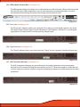
Installation &
Quick Start Guide
Pending the completion of the full PS8
Software and installation manual we have
created this temporary quick start manual
covering a portion of the topics most
commonly asked by users and dealers.
(THIS IS NOT THE COMPLETE MANUAL)
WWW.ARCAUDIO.COM
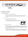
1. COVER PAGE
2. INDEX
3. INTRODUCTION TO THE PS8
4. PACKAGING CONTENTS
6. CONNECTION YOUR PS8
6.1 Analog signal inputs (RCA)
6.1.1 Low Level RCA Inputs
6.1.2 Differential input RCA/Speaker level switch
6.1.3 Hi Level Speaker Input
6.1.4 PS8 Speaker autosense turn on/off jumper
6.2 User interface connections
6.2.1 PSC remote display connection
6.2.2 USB Connection
6.3 Main Power Terminal Connections
6.3.1 Signal Ground Connection
6.3.2 Illumination trigger lead
6.3.3 User profile 2 trigger
6.3.4 User profile 1 trigger
6.3.5 Remote Turn on - Output connection
6.3.6 Remote Turn on - Input connection
6.3.7 +12V Positive battery connection
6.3.8 Chassis ground connection
6.4 Digital inputs & sources
6.41 Coaxial input
6.4.2 Optical Input
6.4.3 Bluetooth Streaming Input
6.5 Other signal inputs
6.5.1 3.5mm Unbalanced Aux input
ARC AUDIO
5. PS8 INSTALLATION AND COMPONENT DESCRIPTION
5.1 Mounting considerations
5.2 Dimensions
5.2.1 External Dimensions
5.2.2 Mounting Dimensions
5.3 PS8 Hardware Components
5.3.1 Cosmetic top cover
5.3.2 Cosmetic top cover under panel
5.3.3 PS8 Main PCB
5.3.4 PS8 Main Chassis Housing (Upper and Lower)
5.3.5 PS8 activity and status display
5.3.5.1 Illuminated ARC Audio & PS8 Logo
5.3.5.2 Digital input confirmation indicator
5.3.5.3 USB connection confirmation indicator
5.3.5.4 Bluetooth connection confirmation indicator
5.3.5.5 PS8 signal clip indicator
5.3.5.6 PS8 User profile lead use indicator
6.6 RCA Signal Outputs
6.6.1 RCA PRE OUT - Signal Outputs
7. PS8 SOFTWARE IINSTALLATION AND REMOVAL
7.1 PS8 Software interface installation general comments and overview
7.3 .NET driver installation
7.4 Software installation
7.4.1 Windows 7 installation guide
7.4.2 Troubleshooting section for software installation
7.5 Uninstallation and removal of the software
7.5.1 PS8 software uninstall general comments and overview
7.6 Updating the PS8 user software
8. UPDATING THE PS8'S FIRMWARE
8.1 Updating the PS8’s operating firmware
9. CONNECTING THE PS8 TO YOUR PC
9.1 PS8 USB failsafe protocol
9.2 Connecting the USB to your PC and the PS8
9.3 “...” Ellipsis check box
9.4 Send preset 1 to PS8
9.5 Send preset 2 to PS8
9.6 Send preset 3 to PS8
9.7 Send all presets
9.8 Retrieve Preset 1 from PS8
9.9 Retrieve Preset 2 from PS8
9.10 Retrieve Preset 3 from PS8
9.10 Work Offline
ARC AUDIO
7.2 System requirements
10. OTHER PS8 FEATURES, USER DEFINED FEATURES AND MORE
10.1 User defined channel names and assignments
10.1.1 Outputs
10.1.2 Channel naming boxes
10.1.3 Channel assignments
10.2 Remote output turn on/off delay user panel
10.2.1 Remote turn on lead (On) delay user control
10.2.1.1 Turn on delay slider
10.2.1.2 Turn on display readout
10.2.2 Remote turn on lead (Off) delay user control
10.2.2.1 Turn off delay slider
10.2.2.2 Turn off display readout
10.3 User preferences
10.3.1 Show temperature in Celsius
10.3.2 Enable Tool Tips
10.3.3 Invert Illumination Trigger
10.4 PS8 password utility and setup
10.4.1 PS8 Password entry for syncing “Password Entry”
10.4.2 Setting a new password “New Password”
10.4.3 Show password
10.4.4 “Set” password
10.4.5 “Clear” reset system
10.4.6 “Cancel” button
10.4.7 “Just set PC password” Password button
10.5 Advanced user more selection
10.6 Export setting files to CSV
10.7 Set frequency range linits panel
11.
USER SOFTWARE GRAPHIC FEATURE OVERVIEW
11.1 Top Header “File”
11.1.1 Open Settings
11.1.2 Save Settings As
11.1.3 Save Settings
11.1.4 Recent Files Button
11.1.5 Import Preset
11.1.6 Export Preset
11.1.7 Export Files to CVS
11.1.8 Exit
11.2 “Sync”
11.3 “Presets”
Preset catagory 1
Preset catagory 2
Preset catagory 3
How presets work
How to save and sync all three presets
Retrieving and Syncing from the PS8
11.4 “Setup”
11.4.1 User input/output channel assignment panel
11.42 Remote turn on/off program panel
11.43 Password definations, setup and system panel
11.44 Bluetooth user interface and setup panel
11.45 User preference setup panel
11.46 Advanced user mode toggle switch
11.5 “Meters”
11.5.1
11.5.2
11.5.3
11.5.4
Signal Input
DSP Output
Signal Output
Foreground
11.6 “Help”
11.6.1 About
11.6.2 Check for new PS8 firmware
11.6.3 Check for new remote firmware
11.6.4 Download user manual
11.6.5 Open User manual
12.
ACTIVE SOFTWARE PANEL HEADER AND FUNCTION OVERVIEW
12.1 Input
12.2 Router (Standard Mode)
12.2.1 Input channel assigned name display
12.2.2 Input/Output signal router assignment check box (Standard Mode)
12.2.2.1 Output channel assigned display
ARC AUDIO
11.31
11.32
11.33
11.34
11.35
11.36
12.3 Mixer Panel (Advanced Mode)
12.3.1 Input channels and invert input polarity
12.3.2 Input/Output channel intersection variable level conrols
12.3.3 Input/Output channel intersection level display box
12.3.4 Input/Output channel intersection summing button
12.3.5 Output channels 1-8 invert polarity boxes
12.3.6
12.4.1
12.4.2
12.4.3
12.4.4
Channels 1-8 crossover filter type window
Channels assigned name display
Channel crossover type check boxes
High Pass crossover filter type adjustment window
12.4.4.1 HP crossover slope selection window
12.4.4.2 HP crossover frequency selection controls
12.4.4.3 HP crossover damping selecton window
12.4.4.4 HP crossover “variable ”Q” adjustment control
12.4.4.5 HP crossover Bessel normalization controls
12.4.5 Low Pass crossover filter type adjustment window
12.4.5.1 LP crossover slope selection window
12.4.5.2 LP crossover frequency selection controls
12.4.5.3 LP crossover damping selection window
12.4.5.4 LP crossover variable “Q” adjustment control
12.4.5.5 LP crossover Bessel normalization controls
12.5 Signal Delay / Channel 1-8 Invert Polarity Control Panel
12.5.1 Channel 1-8 signal delay adjustment utility window
12.5.1.1 Channel assigned name display
12.5.1.2 Channel link/unlink buttons
12.5.1.3 Channel signal delay adjustment slider
12.5.1.4 Channel signal delay adjustment value
12.5.2 Channel 1-8 output invert signal polarity utility window
12.6 EQ Control Panel
12.6.1
12.6.2
12.6.3
12.6.4
12.6.5
12.6.6
12.6.7
12.6.8
12.6.9
Equalization channel selection panel
EQ channel selection check boxes
EQ channel assigned name display
EQ channel frequency value readout display
EQ channel selection, All channels check/uncheck
EQ plot channel selection check boxes
EQ plot selection all channels check/uncheck
Parametric EQ mode selection
1/3rd Octave eq mode selection
ARC AUDIO
12.4 Crossover Control Panel
12.7 Signal output control panel
12.7.1
12.7.2
12.7.3
12.7.4
12.7.5
12.7.6
12.7.7
12.7.8
12.7.9
Master volume control
Output channels 1-8 signal trim control
Channel trim level value readout display
Output channel trim adjustment slider
Channel trim all channels link/unlink button (Tandem)
Output fader controls
Output fader level value readout display
Output fader adjustment slider
Channel name and assigned faders panel access button
13.0) Master Volume Output Control
13.1 Master volume control
13.2 Master volumecontrol indicator
14.0) Bottom Header User Sotware Graphic Feature Overview
14.1 Output channel muting
14.2 Electronic serial number display verification
14.3 Preset selection buton and status indicator
14.3.1 Software position preset status selection and status button
14.3.2 PS8 hardware physical position preset selection and status button
14.4 Offline mode seleciton box
14.5 Phase lock
14.6 Digital Indicator
14.7 USB connection indicator
14.8 System voltage display
14.9 PS8 Internal DSP core temperature
15.0) Replacing/Upgrading The PS8’s Output Devices
ARC AUDIO
12.6.10 Equalization adjustment and controls
12.6.10.1 Individual frequency adjustment slider and bar
12.6.10.2 Individual frequency adjustment fine adjustment buttons
12.6.10.3 Individual band frequency center readout display
12.6.10.4 1/3rd Octave EQ mode “All Flat” Button
12.6.10.5 1/3rd Octave EQ mode “All 1/3rd Octave” reset button
12.6.10.6 Parametric EQ band fine tuning controls
12.6.10.7 All 1/3rd Octave reset button
12.6.10.8 Parametric EQ band, variable frequency selection slider
12.6.10.9 Parametric EQ band variavle frequency value display
12.6.10.10 All “Q’s” reset button
12.6.10.11 Parametric EQ band variable “Q” slider
12.6.10.12 Parametric EQ band variable “Q” value display
12.6.10.13 EQ frequency plotting chart dispaly
16.0) Trouble Shooting Guide
System turn on/off pop
16.2
PS8 not turning on
16.3
No output from Ps8
16.4
PS8 controls not responding smoothly or settings dont appear
accurate when adjusting.
16.5
When using EQ panel there are no sliders on the adjustment screen
16.6
Cannot retrieve settings from PS8
16.7
USB confirmation light on software not flashing
16.8
Temperature reading is displaying Celcius and not Farenheit
16.9
Firmware update failed
16.10 Loss of “AUX” indicator during firmware update
ARC AUDIO
16.1
16.11 USB light does not flash and controls do not respond after firmware update
16.12 PS8 turns on and then shuts off 2 seconds later and continues
“looping”.
16.13 After sending a setting file from the PC to the PS8 the other presets do not
properly reflect what the software is displaying on the other presets.
16.14 After installing/updating the PS8 software onto the PS8 there is no PS8
Software Icon on my desktop or favorites menu.
16.15 When using analog or digital inputs in conjunction with a remote turn on
input trigger, upon first fire up and start the PS8 makes a digital noise and
sometimes does not start up properly.
16.16 The PS8 takes an excessive amount of time to turn on.
16.17 The PS8 takes an excessive amount of time to turn off or will not turn off.
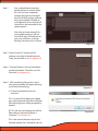
3. Welcome to the PS8
Welcome to the ARC Audio family of performance signal processors and thank you for your purchase of
the ARC Audio PS8 car audio digital sound processor. The PS8 is the most advanced car audio processor
on the market placing the focus of its entire development on placing the power of tuning back into the
hands of the user and the listener. The unit is a unique combination of the highest quality analog and
digital components available giving all levels of user and/or enthusiast the finest product available
whether you are a competitor or simply enjoy music being reproduced as it was intended.
Developed exclusively for ARC Audio by Robert Zeff, Richard Greenway, Brent Waddell, Fred Lynch and
Brad Ott, the ARC Audio PS8 features leading edge technology and design offering listeners in real time
the most transparent and dynamic sound possible of any processor available to the 12 volt market today.
Using the hands on experience and knowledge of the championship ARC Audio sound quality competition team with most every audio processor designed since the early 90's, the PS8's user interface offers
multiple levels of operation giving all users from the most experienced professionals to every day enthusiast's just getting started, the most in-depth and easy to use tuning capability of any digital sound processor on the market.
The ARC Audio PS8 gold plated audiophile designed main PCB uses a specifically designed audio grade
32-bit DSP main processor optimized for operation at 192 kHz and 170mHz operating speed with Dual
72-bit algorithmic volume control processors, eliminating signal compression as volume is increased,
giving the PS8 the most transparent, dynamic and musical signal processing capability of any processor
on the market. In addition, the main DSP in the PS8 uses 32-bit DA/AD converters capable of operating at
192 kHz and a multi channel DSD direct stream digital input, increasing the flexibility of applications and
input types available without any compromise to the sound quality of the end product.
Offering 6 channels of fully differential analog inputs for RCA (Low Level) or Speaker (Hi Level ) operation
with summing capability, Optical and Digital Coaxial inputs, and optional 3.5mm unbalanced accessory,
input the PS8 gives users the ability to customize their own personal listening experience in most any
variation of aftermarket or OEM application.
Leaving no stone unturned, the PS8's PC based user interface offers users the largest and most extensive,
highest resolution selection of user defined tuning features available in any car audio processor on the
market. Features include phase correct crossovers with selectable LP/HP/BP/AP on all 8 output channels,
including Linkwitz-Riley, Butterworth, Variable "Q", and Bessel damping options, 1,998,000 precision
selectable crossover points and 6/12/18/24/30/36/42/48 differential capable slopes on each of the PS8's
output channels. Other features include linkable .01ms resolution signal delay, input and output phase
invert control, an almost unlimited variation I/O signal mixer, precision signal input and output level
controls and an industry first, user defined 8 channels of 31bands per channel 1/3rd octave or 31bands
per channel of fully customizable parametric equalization with single channel and multi channel
"Global" capability, with over 2,284,996,608,000,000 user defined variations at your finger tips.
4. PS8 PACKAGE CONTENTS
(1) ARC Audio PS8 digital sound processor
x6
(6) RCA to speaker lead pigtail adapters
(1) 6.0" USB Interface A to B Cable
(1) Printed PS8 user advisory notice
(1) Printed ARC Audio PS8 warranty policy
(1) Printed PS8 Software quick start notice
x1
x1
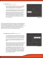
5) PS8 INSTALLATION AND COMPONENT DESCRIPTION
5.1 Mounting Considerations
The ARC Audio PS8 digital sound processor is designed for easy and flexible installation into your vehicle. To
ensure proper operation and long term reliability of your new purchase, please follow the suggestions
below.
1. The PS8 digital sound processor needs to be installed in the signal path between your signal source and
your external amplifier(s).
2. The PS8 digital sound processor must be mounted to a solid surface. Please select a dry clean location in
the trunk or passenger compartment only. Do not mount the PS8 to any area that may experience excess
vibration. Position the PS8 processor in a location that will allow for sufficient air flow with considerations
made for future access and ease of service.
Warning,
Please check the suitability of the installation location before you begin. Do not cut any of the car's structure. Pay
close attention to what is behind the panels or carpet you are mounting to. Often manufactures will hide wires, computers or other electronic devices in the exact areas you will wish to do your install.
When mounting the PS8 to the floor of the vehicle, be sure to inspect underneath the vehicle to prevent damage to the
vehicles fuel delivery system or factory wiring, so as to prevent serious damage or hazardous conditions on your
vehicle
If you do not have experience with automotive electrical and mechanical systems, contact a professional installer.
Paying a qualified installer is almost always cheaper than paying a dealership to repair your car.
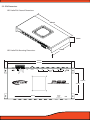
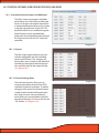
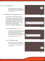
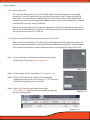
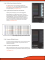
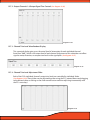
5.2- PS8 Dimensions
ARC Audio PS8: External Dimensions
250mm
30mm
130mm
ARC Audio PS8: Mounting Dimensions
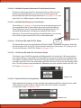
PROFILE 2
ILLUMINATION
USB
SIGNAL GROUND
PROFILE 1
REMOTE - OUTPUT
REMOTE - INPUT
GND
DC IN
+9 - +15v
+12V
245mm
222mm
DISPLAY
CH6
CH5
CH4
CH3
CH2
ANALOG
INPUT
CH1
RCA
SPEAKER
INPUT LEVEL
106mm
ADVANCED DIGITAL SOUND PROCESSOR
OUTPUT
CH1
CH2
CH3
CH4
CH5
CH6
CH7
CH8
DIGITAL
INPUT
CH 1/2
AUX IN
CH 5/6
70mm
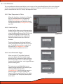
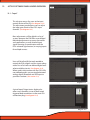
5.3 PS8 Hardware Components
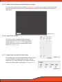
5.3.1 - PS8 Cosmetic top cover
The cosmetic top cover of the PS8 is a 2 piece decorative
assembly that covers the main housing connections and
installation mounting points. To install the cover, care
fully place the extrusion over the top of the main
housing until it is resting flat on the top surface. (This
cover is held in place in conjunction with the PS8 activity
and status display and its associated hardware). (The
inner decorative panel is removable for painting or
alternative finishing by turning over the top cover and
removing the Four (4) 2.5mm Phillips head screws from
the plate. When reinstalling the under plate, make sure
to thread the screws manually to prevent the screws
from stripping.)
5.3.2 - Cosmetic top cover under panel
The cospetic top cover under panel is screwed to the
under side of the PS8 main cover. This panel is removable as it may be painted, powder coated etc to match
the installation or vehicle theme.
5.3.3 - PS8 main PCB
The PS8 main PCB is home for all of the electronics of the
PS8. The main PCB if for some reason needs to be
removed please be sure to practice safe handling
instructions.
Be sure to discharge yourself by grabbing ahold of the
PC8’s RCA barrel connectors first. Then remove the four
screws and then carefully place the PCB into an antistatic
bag.
5.3.4 - PS8 Main Housing (Upper and Lower)
The main housing of the PS8 is comprised of a 2
piece stamped steel chassis that holds the main circuit
board of the PS8. The main chassis is labeled with all
wire connection labeling and also includes the incorpo
rated mounting tabs for installation of the PS8 into your
individual application.
5.3.5 - PS8 Activity and status display
The PS8 activity display gives users visual tools on the
face of the main display unit allowing them, in real time,
to see the current status of the PS8 and its different user
interface based components. The display offers users a
general overview of the interface features and their
current mode of operation.
• Illuminated ARC Audio & PS8 logo - The logos are a
dual operation illuminated display showing users when
the PS8 is powered on or off.
• Digital Input Indicator- This single (Blue) LED, when lit,
indicates when the PS8 is actively receiving digital
signal from a digital source such as optical, digital
coaxial, or Bluetooth (When the Bluetooth accessory
module is in use)
• USB Connection indicator- This single (Blue) LED,
when lit, lets users know when the PS8 is actively
connected to a PC and the user interface is communi
cating with the processor.
• Bluetooth Connection Indicator- This single (Blue)
LED, when lit, lets users know when the PS8 is actively
receiving signal from a linked Bluetooth compatible
device.
• Signal Clip Indicator- This single (Red) LED, when lit or
flashing, lets users know when the processor is sensing
any clipped signal at any part of the signal chain within
the PS8
Ps8
USB
DIGITAL
CLIP
USER
• PS8 User Profile Lead Indicator- This single (Blue) LED,
when lit, indicates that the PS8 is currently being
triggered into one of its three onboard user defined
presets thru one of the 2 onboard ground triggered
profile leads.
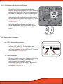
5.3.5.1- Connecting the status display
When installing the PS8 status display carefully
connect the plug dongle into the 8 pin receptacle on the main circuit boards of the PS8. The
receptacle is visible thru the top opening of the
PS8 with the status display removed
(See diagram 5.1). Be careful to note the guide
orientation that indicates the proper direction to
install the plug. DO NOT FORCE THE PLUG INTO
THE SOCKET!
Diagram 5.1
DISPLAY
GND
CH6
+12V
CH5
REM - IN
CH4
P-1
CH3
REM - OUT
CH2
P-2
CH1
ILLUM
SIG GND -
RCA
SPEAKER
INPUT LEVEL
USB
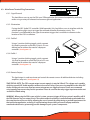
Diagram 6.1
Differential Low/High
(Speaker Level) Inputs
6) CONNECTIONS TO YOUR PS8
6.1 - Analog Signal Inputs (RCA)
6.1.1- PRE IN Low level primary analog Inputs (RCA)
Channels 1,2,3,4,5,6 Inputs - Connect here your RCA signal input leads coming from your
analog source. Each connection is capable of receiving signal levels up to 8 Volts RMS.
(See diagram 6.1)
6.1.2- Differential input RCA/Speaker level switch
This switch allows users to change the operation of the RCA inputs of the PS8 between LowLevel RCA and Speaker Hi-Level operation. (See diagram 6.2)
RCA
SPEAKER
INPUT LEVEL
CH1
6.1.3- Hi Level Speaker inputs
Diagram 6.2
Channels 1,2,3,4,5,6 Inputs - Connect your vehicles factory speaker leads to the RCA inputs of
the PS8 using the provided RCA to speaker lead pigtail adapters. Each input connection, when
in Hi level mode, is capable of receiving HI-Level signals from 1.5V - 20.0V input from any OEM
factory stereo system (See diagram 6.1)
Warning- If using the PS8 as a signal summing device, make sure to verify the signal from
your OEM system with an Oscilloscope and multi meter prior to making your final connections .
6.1.4 - PS8 Speaker Autosense turn on/off jumper
The ARC Audio PS8 has a patented bridged mode
detection circuit incorporated into the design, improving
the flexibility of the PS8 for OEM integration applications.
This mode can detect the BTL (CHIP) used in most head
units and stock amplifiers. When turned on, Bridged
mode detection will sense this chip and turn on the PS8.
BTL Auto detect is activated by removing the PS8's status
display and changing the jumper location as indicated.
(See diagram 6.3)
Please note that BTL Auto detection will not work on all
vehicles and some vehicle may require the remote turn-on
lead input to be connected to the vehicles accessory
circuit.
Diagram 6.3
Disabled Enabled
Auto Sense
6.2 - User Interface Connections-
6.2.1 - PSC display cable connection
GND
+12V
REM - IN
P-1
P-2
PSC Display
Connection
REM - OUT
DISPLAY
ILLUM
6.2.2 - USB Connection
SIG GND -
This connection is for the PS8's optional accessory
controller (ARC Audio PSC). This connection is only
compatible with the PSC's proprietary interconnect cable,
and is only compatible with the ARC Audio PSC Controller
(Sold Separately). (See diagram 6.4)
USB
USB/PC Connection
Diagram 6.4
This port is used to connect your computer to the PS8 via
the provided USB A TO B cable. This connection is
required for the PS8's user utility software to
communicate with the PS8 and adjust its onboard DSP
functions. The PS8's USB interface is USB 1.1/2.0
compatible. (See diagram 6.4)
GND
+12V
REM - IN
P-1
REM - OUT
P-2
ILLUM
6.3.1 - Signal Ground
SIG GND -
6.3 - Main Power Terminal Plug Connections
USB
This lead allows users to use the PS8 in an OEM application for increased compatibility to factory
radios using a variety of balanced and common ground applications.
6.3.2 - Illumination
If using the ARC Audio PSC controller (Sold Separately), this lead allows users to interface with the
vehicles parking light circuit to trigger the onboard controller illumination circuit . This
function is user definable for the type of convenient trigger that is available in reference to the
location of the PS8's installation.
6.3.3 - Profile 2
Using a 3 position latching toggle switch, connect
this lead to ground to switch the PS8 to its P3 user
defined preset without the need of a laptop or
controller (See diagram 6.5)
6.3.4 -Profile 1
Using a 3 position latching toggle switch, connect
this lead to ground to switch the PS8 to its P2 user
defined preset without the need of a laptop or
controller (See diagram 6.5)
Diagram 6.5
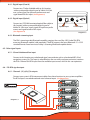
6.3.5- Remote Output
This lead output is used to activate and control the remote turn on of additional devices including
amplifiers, relays etc. (See diagram 6.5)
TAKE SPECIAL NOTE- The PS8's remote output current capacity is rated at 250mA. This voltage out is capable
of driving several ARC Audio amplifiers without the need of a relay. If you are using amplifiers other than ARC
Audio, and they do not use an ultra low current microprocessor-triggered turn on circuit, we recommend
using a quality low current relay for this operation. Please be sure that the relay trigger requirement does not
exceed the 250mA rating.
WARNING- When using the PS8 in your vehicle’s system, you must trigger all of your system’s amplifiers off of
the PS8's Remote Turn- on output circuit. The remote output lead timing is controlled and customizable thru
the setup function of the user utility, allowing the user to control the exact timing on and off requirements for
their particular application, reducing, if not eliminating, the possibility of turn on/off pops and other
unwanted related noises, preventing possible damage to your system’s components.
6.3.6- Remote Input
Connect any triggered +12V signal
remote turn on lead for aftermarket
systems, +12V switched vehicle accessory lead (on not autosense compatible applications,) to turn on and
activate the PS8 and all of its functions
(See diagram 6.6)
6.3.7- +12V Input
+12V Positive fused connection to the
vehicle’s battery or constant power
source. (Fuse rating should be no
higher than 5 amps) (See diagram 6.6)
6.3.8- Ground
Connect this lead to the vehicle’s
chassis or any clean grounding point.
The grounding point should be clean,
free of paint, grease, debris, etc., and
on bare metal. It is not recommended
to connect any ground wire of any
audio component to seat or seatbelt
bolts or hardware.
GND
TURN
ON
3 X 30 AMP MAX
+12V
GND
TURN
ON
+12V
3 X 30 AMP MAX
ARC Audio Inc., USA
ARC Audio Inc., USA
Diagram 6.6
6.3.9 - DC Input Jack
By using an AC/DC wall plug adapter (not Included), the PS8 can be used in home or studio
applications. If you wish to use this feature of the PS8, please make sure to purchase a wall adapter
from a local electronics parts store with the following parameters. To operate this feature you will
be required to jumper a wire lead between the main power plug’s 12V and Remote turn on input
lead connection (See section 6.3). If you power supply is not switched output operation you may
wish to connect a switch inline so you may turn the PS8 on and off.
GND
+12V
P-1
REM - IN
P-2
REM - OUT
ILLUM
SIG GND -
Voltage rating +9V - +15V (Tip Positive)
Current Capacity - Minimum 2 Amps
Plug dimensions - 2.1mm I.D. x 5.5mm O.D.
DC Input Jack
Diagram 6.7
6.4 - PS8 Digital Inputs & Sources
The PS8's digital platform is capable of receiving a variety of digital signals.
Please note that if you choose to run any of the PS8's digital signal inputs, you will be required to
use the PSC controller (sold separately) in order to have control of the system’s volume.
6.4.1 - Digital Input (Coaxial)
Connect any 75 ohm shielded cable to this location
with any compatible digital signal of 48kHz/24-32bit
max, stereo signal, for optimum performance and
signal benefit of this input. (See diagram 6.8)
AUX IN
6.4.2 - Digital Input (Optical)
CH8
Connect any TOSLINK terminated optical fiber cable to
this location with any compatible digital signal of
48kHz/24-32bit max, stereo signal, for optimum perfor
mance and signal benefit of this input.
(See diagram 6.8)
DIGITAL IN
Optical input
Coaxial input
Diagram 6.8
6.4.3 - Bluetooth streaming input
The PS8's streaming audio Bluetooth capability requires the use of the ARC Audio PS8-BTM
accessory Bluetooth module (sold separately). The BTM supports the latest Bluetooth 2.1 + EDR
standard formats found on most of today's streaming Bluetooth capable devices.
6.5 - Other signal inputs
6.5.1 - 3.5mm Unbalanced Aux input
Connect to this location any unbalanced signal source device such as a hardwired MP3, iPod,
navigation system, Etc. This input is selectable thru the user utility and upon activation, removes
the PS8's Channel 5&6 RCA input from the available input sources while in this user operation.
6.6 - PS8 RCA signal outputs
6.6.1 - Channels 1,2,3,4,5,6,7,8 outputs.
Connect your system’s RCA interconnect cables from these locations to your systems amplifiers.
The RCA outputs are unbalanced and not a balanced onput. (See diagram 6.9)
Diagram 6.9
7) PS8 SOFTWARE AND INSTALLATION AND REMOVAL
7.1- PS8 Software Installation and Removal General Comments
The PS8 software and user utility is designed to give you full access to the complete power and feature set of
the ARC Audio PS8. Installation can be completed in a matter of minutes for most users and is compatible
with an extremely wide and diverse selection of laptop computers and operating systems.
7.2- System Requirements
• The PS8 user interface and adjustment software requires a PC with a genuine version of Windows XP,
Windows Vista, Windows 7 and Windows 8 operating system already installed. (NOTE: The PS8 software is
not compatible with Windows 8 RT Tablet operating system as the USB protocol is not compatible with the
Microsoft .Net Framework protocol that the PS8 software operates on.)
• PC hardware restrictions also require that your PC be equipped with a processor with a minimum 1 GHz
minimum processor speed (Minimum recommended) and minimum 512 MB Ram in order to install and
operate the software without possible issues.
• Unlike other processor software the PS8 software utility will automatically update your computer with the
required USB compatibility drivers allowing for a smooth installation process without the need of additional
and time tasking procedures to complete this process.
NOTE- It is recommended that your PC be up to date with all software and hardware driver updates prior to installation of this software to ensure correct installation and operation of this software. These updates should include all
Windows, USB driver and hardware driver updates. Failure to do this could result in complications with the installation of the software. For instructions on updating and installing specific updates for your system please contact the
manufacture of your computer for specific instructions or you may also use your integrated Microsoft Windows
update system already installed on your authentic Windows operating system.
7.3- Microsoft .NET Framework
The PS8 user software operates on the Microsoft .NET Framework for operation of the software on your PC.
When installing the PS8 Software for the first time if you do not have .NET Framework installed on your PC
you will be prompted to install before the installation can proceed. .NET Framework is of no charge and can
either be downloaded automatically during the software PS8 installation process or directly at
http://www.microsoft.com/net
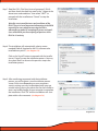
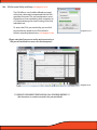
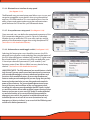
7.4- PS8 Software Installation Guide
7.4.1 - Software Installation
Step 1- Download the latest version of software
from the ARC Audio website on the PS8
product page on the PC you plan to use
with your PS8
Step 2- Download and save the associated file to
your computers desktop and extract the
enclosed zip folder to your PC
Diagram 7.1
Step 3- Open the Zip file and drag the setup file
file in this folder onto your desktop.
(See diagram 7.2)
Step 4- Identify the desktop location that you placed
the PS8 Software installation files.
Step 5- Next double click on the "setup" icon.
Note: Depending on your PC's security settings you may be prompted
with a security warning upon launching this file. If you receive this message when attempting to install the PS8 software, no worries as long as
you are loading this file from the original disc the software is safe for
installation on your computer. If prompted, press the "Yes" button.
Diagram 7.2
Step 6- InstallShield Wizard Accept
At this point the InstallShield Wizard will help
you thru the installation process. To begin
the installation process press the next button
(See diagram 7.3)
Diagram 7.3
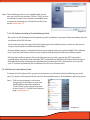
Step 7- Read the PS8's "End User License Agreement" (EULA)
and then check the check box next to the "I Agree to the
above terms and conditions" then select "NEXT" to
proceed with the installationor "Cancel" to stop the
installation.
Note: Be sure to read the terms and conditions of the
EULA. There is a lot of important information in the EULA
especially for users who plan on using the PS8 in
advanced user mode. By accepting the terms and conditions of the EULA you are accepting all portions of the
EULA in it’s entirety
Diagram 7.4
Step 8- The installation will automatically select a recommended (Default) location for the PS8 software to be
installed onto your PC. (See diagram 7.5)
Click on the “Install” button to proceed with the installation or “Cancel” to stop the installation process. You may
also select “Back” to return to the previous step in the
installation process.
Diagram 7.5
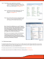
Step 9- After confirming to proceed with the installation
process you will be given a visual installation process
screen. At this time depending on your computers
security settings you may be prompted with a pop up
window asking you to give permission for the installer to
access and make changes to your computer to complete
the installation. Click "OK" and the installation will complete within a few moments. (See diagram 7.6)
Diagram 7.6
Step 9- The installation process is now complete and you can
now use your PS8 user software. Click on "Close" to close
the software installer. For instructions and helpful notes
in regards to launching your software for the first time
please (See diagram 7.7)
Diagram 7.7
7.4.2- PS8 Software Installation Trouble Shooting Guide
- Be sure to turn off all programs and complete any other installations in progress before proceeding with the
installation of the PS8 Software
- If you receive any error messages during the beginning of the installation process make sure that you are
using an account that has administrative privileges.
- If the installation process is interrupted and you are prompted with a pop up box labeled "PS8 Installation
Error" close the install utility and restart your computer and the proceed with the installation process
- If during the installation process the install utility prompts you with a pop up that .NET framework is
required, follow the prompts and download .NET Framework from the Microsoft website free of charge as
directed and then after completing the download and installation of .NET Framework be sure to restart
your PC and then proceed with the installation of the PS8 user software utility.
7.5- PS8 Software UnInstallation Guide
To remove the PS8 software from your personal computer you will need to take the following easy to do
steps. This process will be practically the same for all compatible versions of the Windows operating systems.
Step 1- Click on your computers start button
bringing up the Start Menu. Locate and
double click on the button labeled as
"Control Panel" in the right hand column
to access your PC's Control Panel selection
page. (See diagram 7.8)
Diagram 7.8
Step 2- Depending on your page format search and
locate the control panel option labeled as "Pro
grams" or " "Programs and Features" and double
click on that feature button (See diagram 7.9)
Step 3- Scroll down and locate the file name "PS8" and
click once on it to select and highlight this
program. (See diagram 7.10)
Step 4- Next with the "PS8" software selected locate the
button on the top of the page labeled as "Uninstall" and your PC will take over from there.
Diagram 7.9
Note: During the installation process your PC, depending on your security settings may prompt you with a pop
up message asking for confirmation and permission to
remove this program and/or make changes to your
computer. Click OK and your Windows installer utility
will complete the software removal process.
Note: If you are removing the software for the purpose
of updating it to a newer and up to date version It is
recommended that after any removal of your existing
system you restart your computer before reinstalling any
new versions of the PS8 user software.
Diagram 7.10
7.6 - PS8 Software Update
To update the PS8 software to the newest version you will be required to do a full uninstall of the current version
you have installed on your PC. After uninstalling your current version you can update to the latest version of software by installing it the same way you did the first time.
For step by step instructions to uninstall the PS8 software please see (See Section 7.5)
For step by step instructions for installation of the new software please (See Section 7.4)
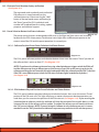
8) UPDATING THE PS8 FIRMWARE
Please follow the instructions below exactly for a successful PS8 firmware update. These
quick steps will allow you for a smooth, easy and trouble free update of the PS8's operation firmware. (Please note your PC must be able to connect to
the internet to complete this process!)
Step 1-
Connect your PC to the PS8 by inserting the
USB end of the A to B cable into your PC and
the type B end into the USB connection port on
your PS8.
Step 2 -
Power up the PS8 as if using in normal
operation.
Step 3 -
Launch the PS8 Software already installed on
your PC.
Step 4 -
After launching, you will be prompted to
sync your PS8 to the PC. (See diagram 8.1)
Step 5-
Locate and click on the button labeled as
"Cancel" (See diagram 8.2)
Step 5 -
Next verify that your PC is communicating with
the PS8 by looking at the flashing USB indicator
located on the bottom of the PS8 software user
utility (See diagram 8.3)
Diagram 8.1
Diagram 8.2
Step 6 -
Diagram 8.3
Using a toothpick, pick tool, or small pointed
straight object insert and press the PS8's
firmware update button. This button is located on the PS8's main chassis inside the small
hole to the right ofthe main power terminal (See diagram 8.4).
Diagram 8.4
Step 7 -
Press and hold this button for a
period of about 5 seconds. When
this task has been completed
correctly the lights on the top of
the PS8 will flash and go solid and
all of your amplifiers hooked up
to the Remote turn on output will
shut off thru the remainder of the
update process.
Now that you have entered Firmware update mode you will see
that the flashing USB indicator on
your user software is no longer
flashing. No worries this is normal.
Diagram 8.5
Step 7 - Return to your PC and on the PS8
software user utility find and locate the
"Help" tab and click on it (See diagram 8.5).
Step 8 - Find and locate on the new drop down
window the header "Check for new PS8
Firmware"(See diagram 8.6).
Step 9 - After completing the previous step a
new pop up window will appear advising
you of one of three things
Diagram 8.6
A) "Cannot read hardware version,
continue?"
This is ok and will not delay your update
press ok and proceed with the installation.
After clicking on you will be prompted by
option 2.
B) "This will erase and reprogram the PS8.
Please do not interrupt the process.
Continue?" (See diagram 8.7)
This is the normal indicator step for the
firmware update. Press ok and do not turn
Diagram 8.7
off or interrupt the update process. If you
have received this message please
proceed to step 11 and finish the update
process
C) "The current version and the updated
version is the same. Continue?"
This message means you are already
updated with the current version of the
PS8 firmware. Please proceed to Step and
enjoy the wonderful sound of the PS8.
Diagram 8.8
Step 10 - After clicking "Ok" the firmware update process
will begin. You will begin to see a lot of scrolling
information in the Firmware update window.
(See diagram 8.8).
This information is the update code and will
continue till it is completed. You will know when it
is completed once it stops (Typically between
"Line 1100 and Line 1500" depending on the
update.) Once this process is complete proceed to
Step 12.
(If after pressing "OK" the process begins and then stops
and the status window stops with "Erase failed" this
means you did not follow the exact steps above and you
will be required to shut down your PS8 software, restart
the software and then redo all of the steps once again
involving the PS8 user utility.)
Diagram 8.9
Step 11 - Once the successful update is complete, find and
locate the button labeled as "Re-Start PS8", Press
this button once and then wait several seconds
while the PS8 reboot's (See diagram 8.9).
Step 12 - After clicking on the "Re-Start PS8" button please
wait about 5-10 seconds for the processor to reinitiate and you will begin to hear audio again, given that
your previous settings prior to the update were set up
correctly.
Step 13- After the PS8 has restarted click on the Red X
(See Diagram 8.10) in the top right corner of the
firmware update window.
Step 14 - Once you have selected to close this window you
will see a pop up window (See Diagram 8.11) that
notify you that you must power cycle the PS8 and its
software to fully initiate the new firmware and to
reconnect the software to the PS8.
Diagram 8.10
Step 15 - Shut down the PS8 user utility and disconnect
the USB from your PC
Step 16 - Reconnect the USB and then Re-Start the PS8
software utility.
Congratulations, you are now completed with
the PS8 update process!
Diagram 8.11
9) CONNECTING THE PS8 TO YOUR PC
9.1 PS8 USB Failsafe Protocol
The ARC Audio PS8 is equipped with an exclusive proprietary USB failsafe protocol A.R.U. and
has been designed to protect your product, your time, and the investment you make into
tuning your vehicle.
With A.R.U. technology and real time updating, the ARC Audio PS8 gives users peace of mind
from the little mishaps that occur during those sometimes lengthy tuning processes,
potentially causing damage to your processor, DSP lockups and much more resulting from
things such as PC power loss, vehicle power loss, accidental cable disconnection, cable damage
from shutting doors, animals, kids etc. With A.R.U., if any of these unfortunate conditions
happen, simply re-establish power to your PC and the PS8 with an undamaged connection,
then re-launch the software and "Retrieve Settings From PS8” and you are exactly where you
left off at the time of the incident. No more sending locked up processors back to the factory to
get unlocked etc.
9.2 Connecting the USB to your PC and the PS8
GND
+12V
REM - IN
P-1
REM - OUT
P-2
DISPLAY
ILLUM
SIG GND -
Connect your PC to the PS8 by inserting the USB
end of the A to B cable into your PC and the
type B end into the USB connection port on your
PS8 (See Section 6.22 ) or (See diagram 9.1). Then be
sure to power up your PS8 first, followed by
launching the PS8 software. After launching, you
will be prompted to choose between offline or
online mode, or to choose to go online by sending or receiving setting files from the PC to the
PS8, or retrieving the settings files from the PS8
and loading it on the PC. (See below).
USB
USB/PC Connection
Diagram 9.1
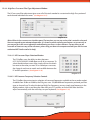
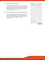
9.3 “...” Ellipsis Check Box
The Ellipsis (See diagram 9.2) check is used to find, locate and assign the preset settings file that is
stored on your PC's hard drive. If you are wanting to send an existing setting file from your PC to the
PS8 you must first click on the "..." ellipsis and then select (Double Click) the desired setting file before
syncing to the PS8.
Diagram 9.2
Diagram 9.3
9.4 Send Preset 1 to the PS8 (See Diagram 9.4)
After selecting the desired settings file on your PC for the
PS8 (See Section 9.1) click and select on this button to
send Preset 1 related settings from this file to the PS8.
The PS8 will automatically sync all of these settings for
preset 1 after selecting this function.
Please note as each setting file stored on your PC
contains information for Presets 1, 2 and 3. If you want to
Sync preset 2 and 3 from this setting file you will need to
click on the "Sync" button on the top header of the
software and select "To PS8" and the desired preset
("Preset 1", "Preset 2", "Preset 3") you want the selected
setting preset files to be loaded to on the PS8.
Diagram 9.4
9.5 Send Preset 2 to the PS8 (See Diagram 9.5)
After selecting the desired settings file on your PC for the
PS8 (See Section 9.1) click and select on this button to
send Preset 1 related settings from this file to the PS8.
The PS8 will automatically sync all of these settings for
preset 1 after selecting this function.
Please note as each setting file stored on your PC
contains information for Presets 1, 2 and 3. If you want to
Sync preset 1 and 3 from this setting file you will need to
click on the "Sync" button on the top header of the
software and select "To PS8" and the desired preset
("Preset 1", "Preset 2", "Preset 3") you want the selected
setting preset files to be loaded to on the PS8. For more
information on how the PS8 presets operate please
Diagram 9.5
9.6 Send Preset 3 to the PS8 (See Diagram 9.6)
After selecting the desired settings file on your PC for the
PS8 (See Section 9.1) click and select on this button to
send Preset 1 related settings from this file to the PS8.
The PS8 will automatically sync all of these settings for
preset 1 after selecting this function.
Please note as each setting file stored on your PC
contains information for Presets 1, 2 and 3. If you want to
Sync preset 1 and 2 from this setting file you will need to
click on the "Sync" button on the top header of the
software and select "To PS8" and the desired preset
("Preset 1", "Preset 2", "Preset 3") you want the selected
setting preset files to be loaded to on the PS8. For more
information on how the PS8 presets operate please
Diagram 9.6
9.7 Send All Presets (See Diagram 9.7)
When selected the "Send All" (See Diagram 9.7) option
allows users to send and sync all three presets from
the setting file identified in the above file box.
If you are selecting this option on initial pc connection
the PS8 will load all three files prior to the software
fully launching. If you select this feature by accessing
files thru the "File" header button after you have
already established communication with the PS8 the
PS8 will load all three files individually. (During this
process you will hear your system load and sync each
preset individually.
Diagram 9.7
On initial startup the PS8 Software and main unit are potentially not
synchronized which could result in changed you make not being
accurate and representing what you see on your user utility. If you do
not want to send a setting file to the PS8 and want to retrieve a
setting from the PS8 that is currently active on the PS8 you must
choose one of the three retrieve setting options below.
9.8 Retrieve Preset 1 from PS8 (See Diagram 9.8)
This feature allows users to retrieve the settings that
are actively stored on the PS8 in the Preset 1 location.
After selecting this option your Software will change
to P1 if it is on another preset and the software will
properly represent the active settings on P1 on the
PS8.
Please note that as each master setting file for the PS8
includes all three preset setting files. If you want your
software to properly reflect all three settings after
retrieving Preset 1 you will need to click on "Sync" in
the top header of the software, then click on "Sync
From PS8" and select the preset "Preset 2" or "Preset 3"
buttons. Upon selecting either of these buttons the
PS8 will software will change to that preset and automatically update the settings to properly reflect the
active settings on the PS8.
Diagram 9.8
9.9 Retrieve Preset 2 from PS8 (See Diagram 9.9)
This feature allows users to retrieve the settings that
are actively stored on the PS8 in the Preset 1 location.
After selecting this option your Software will change to
P2 if it is on another preset and the software will
properly represent the active settings on P2 on the
PS8.
Please note that as each master setting file for the PS8
includes all three preset setting files. If you want your
software to properly reflect all three settings after
retrieving Preset 2 you will need to click on "Sync" in
the top header of the software, then click on "Sync
From PS8" and select the preset "Preset 1" or "Preset 3"
buttons. Upon selecting either of these buttons the
PS8 will software will change to that preset and automatically update the settings to properly reflect the
active settings on the PS8.
Diagram 9.9
9.10 Retrieve Preset 3 from PS8 (See Diagram 9.10)
This feature allows users to retrieve the settings that are
actively stored on the PS8 in the Preset 3 location. After
selecting this option your Software will change to P3 if
it is on another preset and the software will properly
represent the active settings on P3 on the PS8.
Please note that as each master setting file for the PS8
includes all three preset setting files. If you want your
software to properly reflect all three settings after
retrieving Preset 3 you will need to click on "Sync" in the
top header of the software, then click on "Sync From
PS8" and select the preset "Preset 1" or "Preset 1"
buttons. Upon selecting either of these buttons the PS8
will software will change to that preset and automatically update the settings to properly reflect the active
settings on the PS8.
Diagram 9.10
9.11 Work Offline (See Diagram 9.11)
If your PC is not connected to the PS8, you have the
option to operate your PS8 user software in
a stand alone, virtual mode. Offline mode will allow you
to set up all of the system settings prior to ever
connecting to the PS8. If you are connected to the PS8
and wish to change your settings without making an
adjustment, you can either click on the "OFFLINE"
button or simply disconnect the USB from the PC or the
PS8 (Note: in offline mode there are certain functions
that will not be reflected on the PC display as they
require communication with the PS8 DSP chip like
channel naming, serialization, display status etc.)
Diagram 9.11
10) OTHER PS8 FEATURES, USER DEFINED FEATURES, AND MORE
10.1 - User defined channel names and definitions
The PS8’s output assignments and labels
panel allows users the ability to define the
names of all input and output channels for
a improved reference and ease of use when
using the tuning features of the PS8. This
panel also allows users to define the generalized function and assignened fader
placement and orientation of each channel
for future control with the PSC (Optional)
controller.
Diagram 10.1
10.1.1- Outputs
The PS8's eight output channels are individually changeable with the individual
names and functions. This category will
always allow users to refer to the individual
channels by the original channel designation and their place in the output line up.
(See diagram 10.2)
10.1.2- Channel Naming Boxes
Channel naming boxes allow users to
customize the name of each of the PS8's
individual 8 channels of output. To make a
change to all or one of the channel names,
simply click on the desired channel name
box, enter the new name, and then hit
enter. When you are completed with all of
the desired changes, be sure to click on the
“OK” button. (See diagram 10.3)
Diagram 10.2
Diagram 10.3
10.1.3- Channel Function Assignments
Channel assignments allow users to designate the function of each of the PS8's
output channels (See diagram 10.4).
Users may select operational designation
from Front Left, Front Right, Rear Left, Rear
Right, Center, and Bass.
These operations allow users to interface
the channels with the fader controls of the
PS8 that are located on the PSC controller
and also in the output trim. This panel is accessible thru the “Setup” tab drop down menu.
Diagram 10.4
10.2 - Remote output turn on/off delay user panel
The information within this chapter gives etailed
instructions on how to use the user defined remote
turn on output lead (See Section 6.3.5) delays on the
PS8. This panel is accessible thru the “Setup” tab
drop down menu
10.2.1- Remote turn on lead (On) delay user control
Diagram 10.4
The remote turn on lead (On) delay control
interface allows users to customize the time
frame in which the remote turn on lead
activates during the turn on process of the
system. This definable period eliminates the
possibilities for turn on related turn on pop
when you power up your audio system.
This is extremely useful for OEM system
integration where the accessory circuit must
be used to trigger the system, or in some full
aftermarket system applications.
(See diagram 10.4). Users may define a
turn on delay from .01 Seconds to 10.0 Seconds
Diagram 10.5
10.2.1.1- Turn on delay slider (See diagram 10.6)
To change the value of the turn
remote turn on delay timing, simply
click on the slider and drag the adjustment to the desired amount of delay
up to 10.0 seconds. The exact value
will be displayed in the turn on display
readout.
Diagram 10.6
10.2.1.2- Turn on display readout
When a change is made for the timing
delay of the remote turn on lead, the exact
user defined value will be displayed here.
(See diagram 10.7)
10.2.2- Remote turn on lead (Off) delay user control
Diagram 10.7
The remote turn on lead (Off ) delay control
interface allows users to delay the turn off period
of their amplifiers to eliminate turn off pops in
their system. This is extremely useful for OEM
system integration where the accessory circuit
must be used to trigger the system, or in many
full aftermarket system applications.
(See diagram 10.8). Users may define a turn off
delay from .01 Seconds to 10.0 Seconds
Diagram 10.8
10.2.2.1- Turn off delay slider (See diagram 10.9)
To change the value of the remote turn off
delay timing, simply click on the slider and
drag the adjustment to the desired
amount of delay up to 10.0 seconds. The
exact value will be displayed in the turn on
display readout. (See Section 10.2.2.2).
Diagram 10.9
10.2.2.2- Turn Off Delay Readout
When a change is made on the timing
delay of the remote turn on lead, the exact
user defined value will be displayed here.
(See diagram 10.10)
Diagram 10.10
10.3 - User Preferences
The user preference selection panel allows users to access a few personalized features that can be changed
to the users territory measurement preferences as well pop up indicators and illumination controls. This
panel is accessible thru the PS8's "Setup" tab drop down menu.
10.3.1- Show Temperature In Celsius
When this check box is checked, it will display
the PS8's onboard processor temperature
readout (See diagram 10.11) in Celsius. To
display the temperature in Fahrenheit simply
uncheck the check box (See diagram 10.12) and
click “OK”.
10.3.2- Enable Tool Tips
Enable Tool Tips allows users to have an active
interface when using the PS8's software. When
using the different features of the PS8 the user
interface will highlight and allow pop ups
giving tips and basic hints for operation of
certain keystroke buttons etc on the user
interface.
The hints will appear in the lower left hand
corner of your passive area of the Passive user
area . To enable these tool tips simply check
the check box (See diagram 10.13) in the
“Setup” drop down preferences menu.
Diagram 10.11
Diagram 10.12
10.3.3- Invert Illumination Trigger
When using the PSC controller (Optional),
users may connect the illumination trigger
lead to the PS8's main power block connector
This function allows users to select the trigger
function of the illumination wire trigger between
positive and negative.
This input comes stock defaulted to use a
negative trigger however if you so desire you
can simply select the check box
(See diagram 10.14) and change the input to a
positive trigger if it is better suited to this
operation for your specific vehicle. This option
is accessable in the “Setup” drop down preferences menu.
Diagram 10.13
Diagram 10.14
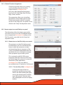
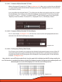
10.4 - PS8 Password Utility and Setup (See diagram 10.19)
The PS8 offers a user/installer defined password
utility that it discretely incorporated into the PS8's
operation firmware. This password prevents unauthorized users from connecting their computers to
a PS8 and retrieving the current settings from that
individual unit.
To access the PS8's password utility you can find
password access panel in your PS8 software
utilities setup drop down menu. (See diagram 10.20)
Diagram 10.19
(Please note that if you are not online and connected to a
PS8 you will not be able to access this function panel.)
Diagram 10.20
****DEFAULT PASSWORD STORED ON PS8 IS ALL SPACEBAR ENTRIES****
(No characters or numbers entered in the password field)
10.4.1 - PS8 Password entry for Syncing (Password entry)
When syncing from the PS8 your PC must have a properly entered
password that matches the password that is currently programmed
into the PS8. The password must be entered in the PS8 password
display (See diagram 10.21)
If the password entered in this display matches the one already in
place on the PS8 the display opening will be green
(See diagram 10.21). If the display opening is red (See Diagram 10.22) it
means that the passwords do not match and will require you to
re-enter a new password that matches to the PS8.
Diagram
g
10.21
10.4.2 - Setting a new password - "New Password"
This display category allows users to enter a new user defined pass
word onto the PS8. To enter a new password you must first have
entered a password in the above "PS8 Password Display"
(See section 10.21) and the software should be indicating this proper
entry with a green highlighted display box (See diagram 10.21).
Diagram
10.22
g
After verifying that you have entered the correct existing password
for the PS8 you may enter the new password into the "New pass
word" display box then click the "Set" button (See diagram 10.23) to
finalize and program this new password to the PS8.
Diagram 10.23
10.4.3 - Show Password
This checkbox allows users to define if they want the password being
entered in the "New Password" display box to be visible upon entry
(See diagram 10.24) or masked when typing (See diagram 10.25).
Diagram 10.24
****DEFAULT PASSWORD STORED ON PS8 IS ALL SPACEBAR ENTRIES****
(No characters or numbers entered in the password field)
Diagram 10.25
10.4.4 - "Set" Password button
"Set" password is used for programming new passwords
into the PS8 and onto your PC. By pressing the "Set"
button (See diagram 10.26) after entering a password that
matches the existing password stored in the firmware of
the PS8 as well as your new desired password this feature
will program the new password on your PS8 and ontothe
PC currently in use as the active password of operation
for that individual PS8.
(Please note that after programming a password to your PC, if
you attempt to connect to another PS8 you will be required to
enter a password that is correct for the PS8 that you are connecting to. If you store another password for a different PS8 and
return to the original PS8 you will have to re-enter the password
as only one password is stored on your PC at a time.)
Diagram 10.26
10.4.5 - "Clear" reset system button
If you do not have or have forgotten the existing pass
word stored in the PS8 you will be forced to send a new
settings file to the PS8 to allow the PC and the PS8 to
have corresponding operation. You may also press
the "Clear" button (See diagram 10.27) to reset all of the
settings on your PC to a default state in which you may
then sync to the PS8 and start from scratch with new user
defined settings.
Diagram 10.27
10.4.6 - "Cancel" button
Pressing the cancel button (See diagram 10.28) will terminate all in progress password modifications that you are
making and return you to the main screen software
utility screen
Diagram 10.28
10.4.7 - "Just set PC password" button
This feature allows you to enter a new password into the
"New password" display area (See Section 10.5.2) and to
program this password onto your PC without programming it into the firmware of the PS8 by pressing the "Just
set PC password" button (See diagram 10.29).
****DEFAULT PASSWORD STORED ON PS8 IS ALL SPACEBAR ENTRIES****
(No characters or numbers entered in the password field)
Diagram 10.29
10.5 - Advanced User Mode
The PS8 offers first of its kind, multi-level user interface modes. These dual user interface levels allow a
combination of user modes that can meet the experience levels of most any user. By selecting the
Advanced Mode operation you will unlock a plethora of advanced tuning features and controls.
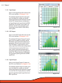
Advanced mode features include a fully customizable Parametric EQ with 248 bands of variable Q and
frequency adjustability with up to +/- 24dB of gain per band, true Bessel and Variable "Q" crossovers,
and an industry first, 100% fully variable mixer control for the detailed routing of input and output
signals.
These features are for advanced and well trained users only. If you choose to enter advanced user
mode, please be advised that you will be on your own as ARC Audio Inc does not offer technical
support to users in this mode. If you find yourself having issues and do not understand the features in
this mode, we recommend that you return to standard user mode or take it to a trained authorized
retailer near you.
Diagram 10.30
To access Advanced User Mode proceed to the PS8 user software's "Setup" drop down user menu
and click on the "Advanced Mode" selection (See diagram 10.30). Once checked the
screen will default to the PS8's Advanced Mode variable mixer panel. You may now proceed with
caution into the abyss of variables that are to be found in the PS8.
To return to Standard User mode from Advanced User mode simply click on the “Advanced Mode”
button to uncheck your previous selection.
(SPECIAL NOTE- Be advised that if you complete a tune and decide to return to standard mode your current settings
will not be compatible and you will have to start over from scratch as many of the adjustments made in "Advanced
Mode" are not found in "Standard Mode".)
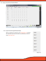
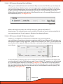
10.6 - Export Settings to CSV / Printable Settings File
Diagram 10.31
Export to CSV allows users to export their entire settings files to a CSV Excel file that can be stored on the PC or
printed for a manual record. When using this operation, it will only export the active settings file that is
currently on the screen at this time. To identify the preset you are actively on, check the preset indicator.
To access this feature locate and click on the "File" button located in the top header passive area.
Once you do this you will see a new drop down menu in which you will find a menu option
labeled as "Export to CSV" (See diagram 10.31).
Once selected you will be promoted to assign a location on your PC to save the file and to create a customized
name for this settings file. To view this file or to print it go to the location on your PC that you saved it to and
open it with Microsoft Excel (Not included in this software package).
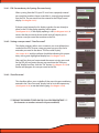
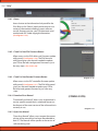
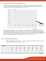
10.7 - Set Frequency Range Limits
Diagram 10.35
"Set Frequency Range Limits" is a user defined operation that allows users to set virtual frequency barriers on
each of the individual bands on all eight channels of crossovers. These limits once set can prevent users from
setting a crossover point outside of the safe operating area of the speakers that are in line with the individual
PS8 output channels. To access the "Frequency Range Limits" feature you must be connected to the PS8 and
on the Crossover user interface panel. When on this panel you will find the access button located below the
"Low Pass" crossover adjustment window (See diagram 10.35).
Once this feature panel is accessed you can set your
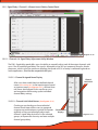
frequency limits by locating the desired channel you
wish to adjust and then setting upper and lower limits
for the channels Low Pass and High Pass filters
(See diagram 10.36).
The benefit to this feature is the increased ability in
allowing users to tune by "Using their ears instead of
their eyes". This simple but effective benefit gives users
the ability to not have to focus on the tuning software
and letting your ears hear the actual change in real time
without the distraction of what the software says of
where your cursor is and without the risk of going to far
and potentially causing damage to the speakers.
Diagram 10.36
11.
TOP HEADER USER SOFTWARE GRAPHIC FEATURE OVERVIEW
11.1 - "File" (See Diagram 11.1)
11.1.1 - Open settings button
Diagram 11.1
"Open Settings" allows users to access one of potentially many previously saved custom user
settings files. Once the file is located and selected, double click on the file and you will be
prompted to choose between working Off Line, On Line, or to send the file to the current active
present on the PS8.
11.1.2 - Save settings as button
"Save Settings As" allows users to save the current active file that they are working on, but with
the ability to create a custom or unique file name for it.
11.1.3 - Save settings
"Save Settings" allows users to save the current active file they are working on using the same
current file name that is currently being used.
11.1.4 - Recent files button
"Recent Files" allows users to retrieve and select the most recent saved settings files that have
been accessed in previous user sessions that have been accessed or saved to the computer’s
settings folder.
11.1.5 - Import preset
"Import preset" allows users to import a third parties individual preset setting file onto their PS8.
This individual file sharing function allows users to share individual presets without having to
upload full setting files which would occupy all three preset positions.
11.1.6 - Export preset
"Export Preset" allows users to Export an individual "Preset" file off of their PC rather than sending
a full settings file which includes all three presets. This feature allows users to share individual
preset settings files without having to release all three of their active presets when file sharing.
11.1.7 - Export files to CSV
Export to CSV allows users to export their entire settings files to a CSV Excel file that can be stored
on the PC or printed for a manual record. When using this operation it will only export the active
settings file that is currently on the screen at this time. To identify the preset you are actively on
check the preset indicator. (See Section 9.4.3.4)
11.1.8 - Exit button
"Exit" Closes the PS8 user software utility. When closing the software you will be prompted with a
pop up window asking you to save your active settings file to prevent any unwanted loss of work.
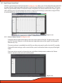
Diagram 11.2
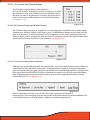
11.2 - “Sync” (See Diagram 11.2)
"Sync" allows users to access the Sync settings file access panel. This panel allows users to send and retrieve
settings to and from the PS8. Uses may load complete setting file packages from their PC and send multiple or
individual presets to the PS8 from within this panel. (See Diagram 11.3)
Diagram 11.3
11.3 - "Presets"
11.31 - Preset 1 category button
Menu access for preset load and copy commands for Preset 1
• Load Preset 1 - Allows users to load saved settings on
Profile 1 (Preset 1) of the PS8 to become
active and also reflect correctly on the
user interface. (See diagram 11.4)
• Copy to Preset 2- Copies current settings stored on the
PS8 Profile 1 (Preset 1) to PS8 onboard
Profile 2 (Preset 2). (See diagram 11.5)
• Copy to Preset 3- Copies current settings stored on the
PS8 Profile 1 (Preset 1) to PS8 onboard
Profile 3 (Preset 3). (See diagram 11.6)
Diagram 11.4
Diagram 11.5
Diagram 11.6
11.32 - Preset 2
Menu access for preset load and copy commands for Preset 2
• Load Preset 2 - Allows users to load saved settings on
Profile 2 (Preset 2) of the PS8 to become
active and also reflect correctly on the
user interface. (See diagram 11.7)
• Copy to Preset 1- Copies current settings stored on the
PS8 Profile 2 (Preset 2) to PS8 onboard
Profile 1 (Preset 1) (See diagram 11.8
• Copy to Preset 3- Copies current settings stored on the
PS8 Profile 2 (Preset 2) to PS8 onboard
Profile 3 (Preset 3) (See diagram 11.9)
Diagram 11.7
Diagram 11.8
Diagram 11.9
11.33 - Preset 3
Menu access for preset load and copy commands for Preset 3
Diagram 11.10
• Load Preset 3 - Allows users to load saved settings on
Profile 3(Preset 3) of the PS8 to become
active and also reflect correctly on the
user interface. (See diagram 11.10)
• Copy to Preset 1- Copies current settings stored on the
PS8 Profile 3(Preset 3) to PS8 onboard
Profile 1 (Preset 1) (See diagram 11.11)
• Copy to Preset 2- Copies current settings stored on the
PS8 Profile 3 (Preset 3) to PS8 onboard
Profile 2 (Preset 2) (See diagram 11.12)
Diagram 11.11
Diagram 11.12
...Presets continued
11.34 - How presets work
The "Settings File" and "Presets" on the PS8 differ slightly from typical presets found on other
processors. On the PS8 Settings file such as the ones you store on your PC when using the PS8
have Preset 1-3 stored within an individual file name. Then each of the individual presets hold
variations that you can create ranging from different inputs, mixer/router configurations, channels
turned on/off, varying EQ settings and more.
When storing settings file on our PC they are indicated as "Settings" package files by the type of
file they are saved as denoted as ".XML" files. Individual settings files can also be stored on your PC
and can be saved on your PC as ".PRE" file.
11.35 - How to save and Sync all three presets from your PC to the PS8
After you have connected your PC to the PS8 you will be prompted with a pop up panel that will
ask you to send or retrieve presets from the PS8 or work offline (See Section 9.0). For the purpose
of this manual we will discuss sending three new presets or one individual setting file to a PS8.
Step 1 - Click on the ellipsis and select your desired master settings
file from your PC and click ok (See diagram 11.13)
Diagram 11.13
Step 2 - Click the check box for "Send Preset 1" (See diagram 11.14)
Step 3 - Click on "OK" and the user interface will automatically
update your screen, place you on "Preset 1" or "P1" and send
all of the setting for this preset to the PS8.
Step 4 - Select "Sync" from the top header button panel
(See diagram 11.15) and you will be prompted once again by
the Sync selection panel
Diagram 11.14
Diagram 11.15
Step 5 - Select "Send Preset 2" (See Diagram 11.16) and press on the
"OK" button. After this the software will be change over to
"Preset 2" or "P-2" and it will automatically sync the information to preset 2 to the PS8
Diagram 11.16
Step 6 - Select "Sync" from the top header button panel
(See diagram 11.17) and you will be prompted once again by
the Sync selection panel
Diagram 11.17
Step 7 - Select "Send Preset 3" (See diagram 11.18) and press the OK
button. After this the software will be change over to
"Preset 3" or "P-3" and it will automatically sync the information to preset 3 to the PS8
Diagram 11.18
11.36 - Retieving Presets and Syncing from the PS8 to the PC-If you are retrieving presets from the PS8 you
will repeat this same process however instead you will be indicating the user utility to "Retrieve
Preset 1" (See diagram 11.19) etc with the same process as above.
Diagram 11.19
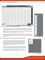
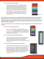
11.4 - "Setup"
11.4.1 - User input/output channel assignment panel
(See diagram 11.20)
User defined channel assignment gives users the ability
to customize all input and output channel names.
Included in this panel is unique designation controls
allowing users to define the operation of each channel for
combined use of exterior control sources etc.
(See Section 10.1 for detailed instructions)
Diagram 11.20
11.4.2 - Remote turn on output program panel
(See diagram 11.21)
Remote output setup allows users to customize and self
define the timing of the remote turn on output needed
for the individual vehicle installation. Adjustments
include remote out turn on from .01 - 10.0 seconds and
remote out turn off from .01 - 10.0 seconds.
(See Section 10.2 for detailed instructions)
Diagram 11.21
11.4.3 - Password definitions, setup and system panel
(See diagram 11.22)
The PS8 and its user defined settings files are protected
by a digitally embedded user defined password protocol.
Every PS8 comes with a default password of "
". (All
Spaces) Changing the password prevents unauthorized
access and/or retrieval of the setting files that are currently
on the PS8's DSP preventing them from being modified,
changed or altered.
(See Section 10.4 for detailed instructions)
(Note: The factory default password is all empty spaces (No
characters entered). If you do not have the assigned password you
will not be able to retrieve and sync your PC to the current settings
on the PS8 and should take it back to the dealer who established
the password on your system. You may also restore the system
back to its default settings and start a new customized tune
yourself.)
Diagram 11.22
11.4.4 - Bluetooth user interface & setup panel
(See diagram 11.23)
The Bluetooth user password setup panel allows users to sync and
recognize compatible source devices when using the optional
accessory PS8 BTM interface. This user interface gives users the
ability to password protect and encrypt their communications
portal between the PS8 and the sync'd Bluetooth device.
11.4.5 - User preferences setup panel (See diagram 11.24)
Diagram 11.23
Once accessed, users can define the operational parameters of the
PS8's temperature diagnostics system in Celsius or Fahrenheit,
Whether or not to enable the PS8's user utility tool tips and the
polarity of the illumination trigger when using the optional PSC
(See Section 10.3 for detailed instructions)
11.4.6 - Advanced user mode toggle switch (See diagram 11.25)
Selecting this feature gives users the ability to access the PS8's
advanced tuning features mode unlocking the extended power of
the PS8. Advanced features include a fully variable I/O signal mixer,
Bessel and Variable "Q" crossover and a fully user definable, up to
31 bands per channel of parametric EQ with variable Q and
frequency center (From 20Hz to 20kHz) on every band of every
channel. (See Section 10.5 for detailed instructions)
(IMPORTANT NOTE: The PS8's advanced user mode features should
only be used if you are a well versed and experienced system tuner
with extended knowledge in the more advanced operations and
functions of the available features. By accessing the advanced
features mode you acknowledge that you are saying that you fully
know and understand what you are doing and understand the
power of these features. Per your acknowledgement and acceptance of the terms and conditions of the user agreement when
installing this software you acknowledge that ARC Audio, its dealers and other entities do not offer technical support for any of these
features and you are on your own. ARC Audio, its authorized dealers and other entities in no event will be held accountable for
damage to your vehicle, the products installed within and/or to
individual persons as a result of user error (intentional or not),
improper use (direct or indirect), or as a result of the PS8 being used
outside of its defined parameters.)
Diagram 11.24
Diagram 11.25
11.5 - "Meters"
11.5.1 - Signal Input
Access to the Signal Input VU meter on the
PS8's user interface. (See diagram 11.26)
The onboard Signal Input VU meter gives
users the ability to visually see the indi
vidual signal level of all 6 channels of input
of the PS8. Display features include physical signal level, peak signal level and RMS
signal level. This meter is also used in cojunction with the input panel for signal
summing of some vehicles OEM factory
radio signals.
Diagram 11.26
11.5.2 - DSP Output
Access to the DSP Output VU meter on the
PS8's user interface. (See diagram 11.27).
The onboard DSP Signal Output VU meter
gives users the ability to visually see the
individual signal level of all 8 channels of
output post mixer/router controls on the
PS8. This Meter is a great tool to use to
verify signal level and correct configuration
of the router/mixer into the DSP's crossover section to prevent overdriving or
misrouted signals into the tuning portion
of the DSP. Display features include physical signal level, peak signal level and RMS
signal level.
Diagram 11.27
11.5.3 - Signal Output
Access to the Signal Output VU meter on
the PS8's user interface. (See diagram 11.28).
The onboard Signal Output VU meter gives
users the ability to visually see the individual signal level of all 8 channels of signal
as it exits the PS8. Display features include
physical signal level, peak signal level and
RMS signal level.
Diagram 11.28
11.6 - "Help"
11.6.1 - About
Access button to the information hub panel for the
PS8. When in the "About" panel you have access to a
variety of information including current software
version, firmware version, your PS8 electronic serial
number and ARC Audio copyright information.
(See diagram 11.29).
Diagram 11.29
11.6.2 - Check For New PS8 Firmware Button
Allows access to the PS8's Main unit Firmware update
utility panel (See diagram 11.30). The PS8 firmware
utility panel gives you the tools needed to update
your PS8 to the latest and greatest firmware in just a
few easy steps. (See Section 8.0)
11.6.3 - Check For New Remote Firmware Button
Diagram 11.30
Allows access to the PSC controller firmware update
utility panel (See diagram 11.31). The PS8 Utility panel
gives you the tools needed to update your PS8 to
the latest and greatest firmware in just a few easy
steps .
11.6.4 - Download User Manual
"Download User Manual" allows users to download a
version specific manual that is suited and focuses on
the features of the exact version of the software that is
currently in use.
11.6.5 - Open User Manual
"Open User Manual" allows users to open the current
version of the manual that has been downloaded to
their PC. The Manual will be specific to the version of
software being used.
(COMING SOON)
Diagram 11.31
12.
ACTIVE SOFTWARE PANEL HEADER OVERVIEW
12.1 - "Input"
This tab gives access for users to the input
control section of the PS8 (See diagram 12.1).
This adjustment panel allows users to adjust
the input gain of each of the PS8's input
channels. (See diagram 12.2)
Diagram 12.1
Most adjustments will be global in a lot of
systems however the PS8 offers user defined
individual adjustments on every channel for
such applications as multi channel input
signal summing (In combination with the
PS8’s onboard signal meters) or varying inputs
for multiple sources.
Diagram 12.2
Users will also find all the tools needed to
control the PS8's digital and Aux inputs along
with a first of its kind user defined digital auto
select and delay circuits (See diagram 12.3).
When used in conjunction with the PS8's fully
user defined presets you can toggle between
analog, digital, Bluetooth and Aux input to
your hears content. (See section 11.3)
Diagram 12.3
A wired Input/Output status display also
offers users the ability to see all hard wired
triggered lead connections to the main PS8
connection plug (See diagram 12.4)
Diagram 12.4
12.2 - Router Control Panel (Standard Mode)
Diagram 12.5
12.2.1- Input Channel Assigned Name Display
When in standard user mode, this area (See diagram 12.5) indicates
the individual input channel and the user defined name for this
input. (See Section 10.1).
Diagram 12.6
12.2.2 - Input/Output Signal Router Assignment Check Box Grid
The Input/Output router assignment grid allows you to select the specific path and route of any of the 6
channels of analog in any configuration to any of the eight channels of output on the PS8. To select a path
intersection, simply click on the desired checkbox. (See diagram 12.7).
Channel 5&6 Input
Summed to Channel
8 output
Diagram 12.7
If you need to sum multiple input channels together to an individual output channel (For example, Signal
summing for OEM integration, or mono assignment of two channels for subwoofer applications), the system
will automatically adjust the input path signal level between the channels to prevent unwanted clipping and to
balance the signal level equally between the selected channels by balancing the total signal level of all of the
inputs into the single channel to not exceed 100% total signal level. (See diagram 12.7).
12.2.2.1- Output Channel Assigned Display
When in standard user mode, this area (See diagram 12.8) indicates the individual output channels and
the user defined names for these outputs (See Section 10.1)
Diagram 12.8
12.3 - Mixer Control Panel (Advanced mode)
12.3.1 - Input Channels & Invert Polarity Check Boxes
Diagram 12.9
When in Advanced mode, the numerical values down the left side of the active
panel window identify the PS8's six RCA input channels. Below each number is a
check box that gives users the ability to invert the polarity of the signal coming
into the mixer on its individual channels. (See diagram 12.9).
This feature gives greater flexibility to combine input polarity and custom signal
mixing for things like phantom center channels and true rear environmental rear
fill applications.
Diagram 12.10
12.3.2 - Input/Output Channel Intersection Variable Level Controls
In Advanced mode, rather than clicking on a check box and
having a fixed signal level from your input channels routed to
the output channels, you have the ability to do any level of
mixed signal level on independent or multiple channels to a
single output. (See diagram 12.10).
The dials are controllable by placing your mouse pointer on the
dial and dragging the dial to the desired location, clicking on it
and using the arrow keys to change the value, or by double
clicking on the Channel Intersection display (See diagram 12.11).
Diagram 12.11
Note: When in Advanced user mode and combining channels in the mixer for the purpose of signal summing, creating a mono subwoofer or center channel out etc., you must not exceed a total output value of 1.0 (Or 100%) signal
into the crossover section of the DSP. Doing so will cause the system to prematurely clip and/or distort at moderate to
high volume levels and potentially cause serious damage to the system and its components. It is recommended that
when combining any number of input channels to a single or combined output, to use the PS8's on board real time
signal status meters (See Section 11.5).
12.3.3- Input/Output Channel Intersection Level Display Boxes
The intersection level display boxes display the individual level
of each signal path intersection between the inputs and the
outputs. The display boxes also act as clickable level buttons for
the corresponding dials. (See diagram 12.12)
By simply double clicking on these boxes you can toggle the
corresponding mixer dial from 0.0 to 1.0, or you can click on the
box and manually enter a value from 0.00 - 1.0 with your
number keys.
Diagram 12.12
12.3.4 - Input/Output Channel Intersection Summing Button
Mixer intersection summing buttons allow you to simply click
on them and reduce the level of the channels indicated above
and below the button to a level of 50% each into the given
channel. (See diagram 12.13)
This operation is optimized for summing two channels
together for summed mono operation (For Example summed
mono subwoofer applications.)
Diagram12.13
12.3.5 - Output Channels 1-8 Invert Polarity Check Boxes
When in Advanced mode, the numbered check boxes across the bottom of the mixer active panel area
(See diagram 12.14) allow you to invert the PS8's output channel polarity 180 degrees for each of the 8 output
channels individually. These settings mirror the check boxes found in the Signal Delay active panel in the user
interface.
Diagram 12.14
12.4 - Crossover Control Panel
Diagram 12.15
12.4.1 - Channels 1-8 Crossover Type Selection Window
The crossover type selection window gives users the
ability to identify the individual output channels
and the types of crossovers that are available on
each of the PS8's output channels. (See diagram 12.16)
12.4.2 - Channel Assigned Name Display
After users have established user defined channel
names (See section 10.1) in the input/output channel assignment panel, (See diagram 12.16) defined
channel names are displayed in this area for easy
use and recognition while setting up the system
crossovers.
12.4.3 - Channel Crossover Type Check Boxes
To select the type of crossover needed for each
channel simply click on the desired check box (dot)
in correspondence with the channel and crossover
type you are wanting. (See diagram 12.16)
Diagram 12.16
Channel Name
Crossover Types
12.4.4 - High Pass Crossover Filter Type Adjustment Window
The HP crossover filter adjustment gives users all of the tools needed to customize the High Pass portion of
each channel individual crossovers. (See diagram 12.17)
Diagram 12.17
(Note: When in the crossover user interface panel, if at any time you see any section that is muted in color and
does not respond to your attempted operation, it is because you do not have your features set up correctly or
you may not be in the correct operation mode allowing you access to these features. If at any time you are
uncertain of how to use any of these features, please stop, put down the computer and take your vehicle to an
authorized ARC Audio retailer for help.)
12.4..4.1- HP Crossover Slope Selection Window
The PS8 offers users the ability to select between
6/12/18/24/30/36/42/48 dB slopes on all of its crossovers. To
select the desired crossover slope, simply click on the check
box next to the value you want. If on a band pass crossover,
the slopes do not have to match and can differ between the
LP and HP operations. (See diagram 12.18)
Diagram 12.18
12.4.4.2 - HP Crossover Frequency Selection Controls
The PS8 offers the most extensive selection of crossover frequencies available to the car audio market.
Available from 20.0hz to 20.0kHz, the PS8 gives users 199,800 different frequencies per band, per filter
type, to choose from. To select the desired High Pass frequency, you can simply type frequency in the
display readout, click on and drag the slider with your PC's pointer, or click on the slider and then
adjust incrementally with the arrow keys on your keyboard. (See diagram 12.19)
Diagram 12.19
12.4.4.3 - HP Crossover Damping Selection Window
Offering users traditional Butterworth and Linkwitz-Riley crossovers, the PS8 allows you to critique the
special needs of your individual system and its tuning parameters. Simply by clicking the designator
next to the desired damping type, you can assign either of the available damping filters to the particular filter type of each channel of the PS8. When using band pass mode on the PS8, you may have
different types of damping on each portion of the channel you are on (For example Butterworth on HP
and Linkwitz-Riley on LP). (See diagram 12.20)
Diagram 12.20
When in advanced user mode, users will also have access to Bessel and Variable "Q"
damping types. These damping types are also mixable in BP mode and are only recommended for the
most experienced users. No tech support is offered on these damping features.
12.4.4.4 - HP Crossover Variable "Q" Adjustment Control
Variable "Q" is available only in advanced user mode and is only recommended for
users with plenty of experience, and previous experience with this type of feature. ARC Audio does not
offer technical support, tuning suggestions, or help with this feature. If you "MUST" use this feature and
are unfamiliar with its operation, take your vehicle to an advanced tuning and installation technician to
tune it for you.
Diagram 12.21
To select Variable "Q" damping type, you must select the corresponding check box to this feature (You
can only achieve this when in advanced user mode). Once in Variable "Q" operation, you will be limited
to its natural parameters based on a 12dB slope (See diagram 12.21 and then this can be adjusted thru
the "Q" control (Slider) on the right hand side of the corresponding adjustment window by dragging
the slider, clicking on the slider and using the arrow keys on your keyboard or manually typing in the
desired value. (See diagram 9.63)
Diagram 12.22
12.4.4.5 - HP Crossover Bessel Normalization Controls
Bessel damping type is available only in advanced user mode and is only recommended for users with plenty of experience, and previous experience with this type of feature. ARC
Audio does not offer technical support, tuning suggestions, or help with this feature. If you "MUST"
use this feature and are unfamiliar with its operation, take your vehicle to an advanced tuning and
installation technician to tune it for you.
Diagram 12.23
To select Bessel damping type, you must select the corresponding check box to this feature (You can
only achieve this when in advanced user mode). Once in Bessel operation, you may adjust the Bessel
damping thru the normal slope type controls and the Bessel normalization controls on the right hand
side of the corresponding adjustment window by dragging the slider, clicking on the slider and using
the arrow keys on your keyboard or manually typing in the desired value. (See diagram 12.23)
12.4.5 - Low Pass Crossover Filter Type Adjustment Window
The LP crossover filter adjustment gives users all of the tools needed to customize the Low Pass portion of
each channel’s individual crossovers. (See diagram 12.24)
Diagram 12.24
(Note: When in the crossover user interface panel, if at any time you see any section that is muted in color and does
not respond to your attempted operation, it is because you do not have your features set up correctly or you may not
be in the correct operation mode allowing you access to these features. If, at any time, you are uncertain of how to
use any of these features, please stop, put down the computer, have a beverage, visit www.arcaudio.com, or use
Google to find an authorized ARC Audio retailer for help.)
12.4.5.1 - LP Crossover Slop Selection Window
The PS8 offers users the ability to select between
6/12/18/24/30/36/42/48 dB slopes on all of its crossovers. To select
the desired crossover slope, simply click on the checkbox next to
the value you want. If on a band pass crossover, the slopes do not
have to match and can differ between the LP and HP operations.
(See diagram 12.25)
Diagram 12.25
12.4.5.2- LP Crossover Frequency Selection Controls
The PS8 offers the most extensive selection of crossover frequencies available to the car audio market.
Available from 20.0hz to 20.0kHz, the PS8 gives users 199,800 different frequencies per band, per filter
type, to choose from. To select the desired Low Pass frequency you can simply type frequency in the
display readout, click on and drag the slider with your PC's pointer, or click on the slider and then adjust
incrementally with the arrow keys on your keyboard. (See diagram 12.26)
Diagram 12.26
12.4.5.3 - LP Crossover Damping Selection Window
Offering users traditional Butterworth and Linkwitz-Riley crossovers, the PS8 allows you to critique the
special needs of your individual system and its tuning parameters. Simply by clicking the designator
next to the desired damping type, you can assign either of the available damping filters to the particular
filter type of each channel of the PS8. When using band pass mode on the PS8 you may have different
types of damping on each portion of the channel you are on (For example Butterworth on HP and
Linkwitz-Riley on LP). (See diagram 12.27)
Diagram 12.27
When in advanced user mode ( users will also have access to Bessel and Variable "Q"
damping types. These Damping types are also mixable in BP mode and are only recommended for the
most experienced users. No tech support is offered on these damping features.
12.4.5.4 - LP Crossover Variable "Q" Adjustment Control
Variable "Q" is available only in advanced user mode
and is only recommended for users with plenty of experience, and
previous experience, with this feature. ARC Audio does not offer
technical support, tuning suggestions, or help with this feature. If you
"MUST" use this feature and are unfamiliar with its operation, take your
vehicle to an advanced tuning and installation technician to tune it for
you.
To select Variable "Q" damping type, you must select the corresponding check box to this feature (You can only achieve this when in
advanced user mode). Once in Variable "Q" operation, you will be
limited to its natural parameters based on a 12dB slope.
This can be adjusted thru the "Q" control
(Slider) on the right hand side of the corresponding adjustment
window by dragging the slider, clicking on the slider and using the
arrow keys on your keyboard, or manually typing in the desired value.
Diagram 12.28
(See diagram 12.28)
12.4.5.5 - LP Crossover Bessel Normalization Controls
Bessel damping type is available only in advanced user mode and is only recom mended
for users with plenty of experience, and previous experience, with this type of feature. ARC
Audio does not offer technical support, tuning suggestions, or help with this feature. If you "MUST" use
this feature and are unfamiliar with its operation, take your vehicle to an advanced tuning and installation technician to tune it for you.
To select Bessel damping type you must select the corresponding check box to this feature (You can
only achieve this when in advanced user mode). Once in Bessel operation, you may adjust the Bessel
damping thru the normal slope type controls and the Bessel normalization controls on the right hand
side of the corresponding adjustment window by dragging the slider, clicking on the slider and using
the arrow keys on your keyboard or manually typing in the desired value. (See diagram 12.29)
Diagram 12.29
12.5 - Signal Delay / Channel 1-8 Output Invert Polarity Control Panel
Diagram 12.30
12.5.1 - Channels 1-8 Signal Delay Adjustment Utility Window
The PS8's Signal delay panel offers users the ability to manually adjust each of the output channels with
up to 12ms of variable signal delay. The signal is adjustable in true .021ms increments found in 48mHz
processors, which is also the maximum sampling rate found in 99.9% of today's traditional high end car
audio applications. (Don't let the competition fool you.)
12.5.1.1- Channel Assigned Name Display
After users have established user defined channel
names (See section 10.1) in the input/output channel
assignment panel (See diagram 12.31), defined channel names are displayed in this area for easy use
and recognition while setting up the individual
channel delay settings.
Channel
Link/Unlink
12.5.1.2 - Channel Link/Unlink Button (See diagram 12.31)
Checking or un-checking on these individual
channel check boxes allows users to group and
ungroup any combination or number of channels Channel Name
together so they can individually adjust each
Displays
channel’s signal delay by itself, or in the selected
groups, to improve the accuracy and ease multiple
channel group delay.
Diagram 12.31
12.5.1.3 - Channel Signal Delay Adjustment Slider (See diagram 12.32)
Diagram 12.32
The delay slider allows users to make the physical value change to the individual channel’s signal delay
level. To adjust the slider’s position, you may click and drag the slider with your PC's pointer or mouse
and/or you may click on it and then, using the arrow keys, you may increase or decrease the amount of
delay with the left and right arrow keys or toggle between the sliders with the up and down arrow
keys. If you have any of the channel linking check boxes checked you will be able to adjust multiple
sliders at one time
12.5.1.4- Channel Signal Delay Adjustment Value (See diagram 12.33)
When making changes to the PS8's signal delay value sliders, these display boxes will indicate your
individual channel’s current level of signal delay in an accurate readout to the nearest .021ms increment. In addition to the value sliders, you may also physically type a known value directly into the
window and press enter or tab to have the PS8 immediately represent that setting.
Diagram 12.33
12.5.2 - Channel 1-8 Output Invert Signal Polarity Utility Window
(See diagram 12.34)
To invert any of the 8 output channels’ polarity 180 degrees,
simply click on the corresponding check boxes in the polarity
utility window. When checked, your selection will be represented in the mirroring polarity check boxes located in the
PS8's Router/Mixer user panel (See section 12.2) depending
on which user mode you are in.
Diagram 12.34
12.6 - Equalization Control Panel
The PS8 offers users one of the most advanced equalizer options available to the car audio market. Depending
on the user mode being accessed during operation, users have access to eight channels of 31-Band, 1/3rd
Octave equalization in .25dB steps, and a first of its kind, global and linking mode, unheard of in existing mobile
electronics designs. Advanced mode users, have the option of the 31-band, 1/3rd octave EQ, or 8 channels of
31-band parametric EQ with fully variable frequency centers and band "Q".
12.6.1 - Equalization Channel Selection Panel
To make adjustments to the EQ on the any of the eight channels
on the PS8 (whether 1/3rd Octave or Parametric), users must
select the desired channels to be affected. This section is the
location that users will have to interface with to make these
channel selections during the tuning process. (See diagram 12.35)
Diagram 12.35
12.6.2 - Channel Selection Check Boxes
To select the desired channel to be effected by adjusting
the sliders while in EQ mode, use your pointer/computer
mouse and click on the corresponding check boxes to
select the channel(s) of operation you wish to work with. If
no channels are selected, there will be no audible adjustments made until you reselect a channel. When in Third
Octave mode, you may select more than one channel at a
time, allowing you to tune multiple channels simultaneously without the loss of the independent channels tune.
(See Diagram 12.36)
Diagram 12.36
(Note: The PS8 is the first of its kind processor to allow unlimited linking/Unlinking of channels for independent and
grouped adjustment without the loss of a combined channel’s existing settings. When channels are grouped in
groups of 2 channels or more, the EQ display will display the current settings of the lowest numbered channel in the
grouping. Although it only shows the one channel, rest assured that your other channel’s previous settings are still
as they were before you linked them.)
(Special Note: EQ Channel linking is only available when using the Third Octave EQ and is not available in Parametric mode.)
12.6.3 - Channel Assigned Name Displays
After users have established user defined channel names
(See section 10.1) in the input/output channel assignment panel
(See diagram 12.37) , defined channel names are displayed in this
area for easy use and recognition while setting and tuning the
individual channel EQ settings.
12.6.4 - Channel Frequency Value Readout Display
Diagram 12.37
Each of the PS8's output channels have a corresponding adjustment display readout showing you the actual individual
adjustment level of all 8 channels simultaneously, with
reference to the EQ frequency band you currently have selected.
(See diagram 12.38)
12.6.5 - EQ Channel Selection, All Channels Check/Uncheck
Diagram 12.38
The Check/Uncheck All feature allows you to check, confirm, or
uncheck all of the PS8's output channels with a single click. The
exact function of check or uncheck is based on the existing
check box configuration. If 2 boxes are checked and you click
Check All, all of the eight channels will now be selected. If the
"Check All" checkbox is marked when you click on this feature, it
will then erase the check boxes from all eight channels.
(See diagram 12.39)
Diagram 12.39
12.6.6 - EQ Plot Channel Selection Check Boxes
By selecting one or more of the EQ plot check boxes
(See diagram 12.40), users may see the exact EQ curve they
have created in color coordinated line graphs displayed in
the EQ plot display. (See diagram 12.40)
12.6.7 - EQ Plot Selection All Channels Check/Uncheck
Selecting this button allows you to select displayable
plotting graphs on all eight output channels. The exact
function of check or uncheck is based on the existing check
box configuration. If 2 boxes are checked and you click
Check All, all of the eight channels will now be selected. If
the "Check All" checkbox is marked when you click on this
feature, it will then erase the check boxes from all eight
channels. (See diagram 12.40)
Diagram 12.40
EQ Plot Display (Only displays channels that are checked)
12.6.8 - Parametric EQ Mode Selection
This feature activation checkbox allows you to activate the PS8's
Parametric EQ mode. This mode is only accessible when in
Advanced User Mode.
12.6.9 - 1/3rd Octave EQ Mode Selection
When in Advanced user mode, you may select this check box to
change from Parametric EQ mode back to Third Octave EQ mode.
(See diagram 12.41)
Diagram 12.41
12.6.10 - Equalization Adjustment And Controls Panel
Diagram 12.42
When using the EQ adjustment panel, this area will provide you with all controls needed for adjustment
of the different bands of EQ, +/- 24dB, for each of the selected output channels of the PS8. (See diagram 12.42)
12.6.10.1 - Individual Frequency Adjustment Slider And Bar
Diagram 12.43
Each output channel of the PS8 has 31 individual slider controls to adjust and refine the frequency
equalization of the selected channel(s). These sliders are dedicated to an individual frequency which is
displayed below each slider . To adjust the sliders position, simply click on the slider
bar (See diagram 12.43) and use the arrow keys for refined adjustment of that band, or click and grab the
slider tab (See diagram 12.43) for larger drag type adjustments.
When using the arrow keys on the keyboard for fine tuning adjustment, the up and down arrow keys will
change the sliders position and adjustment value in .25dB increments while the left and right arrow keys
will allow you to toggle between the actively displayed bands on the EQ without having to use the PC's
mouse or pointer to make the changes.
12.6.10.2 - Individual Frequency Adjustment Fine Adjustment Buttons
If fine point adjustment of the EQ is desired thru the use of the mouse or
pointer’s point and click feature, you may do so by hovering over the
desired individual sliders fine adjustment buttons (See diagram 12.44) and
adjust the EQ in .25dB increments similar to the arrow key operation.
12.6.10.3 - Individual Band Frequency Center Display
These displays (See diagram 12.44) give users the exact tuning frequency of
the corresponding the EQ slider above this position will have effect on.
These frequencies, unless customized while using the Parametric EQ in
advanced mode operation, will represent traditional Third Octave
frequencies. If you wish to change these tuning frequencies, you may only
do so while using the Parametric EQ when in Advanced mode.
Diagram 12.44
12.6.10.4 - 1/3rd Octave EQ mode “All Flat” Button
Frequency
Display
This feature allows users to reset all bands of EQ back to “0dB”. To complete this process select the
desired channels of EQ in the “EQ Channel selection check boxs” (See Section 12.6.2) that you wish
to reset and then press the “All Flat” button (See Diagram 12.45)
12.6.10.5 - 1/3rd Octave EQ mode “All 1/3rd Octave” Button
This button is part of the PS8’s proprietary failsafe protocol. In the event of a USB communication
error when sending or syncing files to or from the PS8 on long runs of cable or thru multiple extension cables etc and one of the 1/3rd Octave EQ frequency bands incorrectly reads 20.0K users may
manually correct this error if the automated system fails to correct it due to out of parameter conditions. To use this feature select the channel(s) affected by this error and then click on the "All 1/3rd
oct" button. (See Diagram 12.45)
Diagram 12.45
12.6.10.6 - Parametric EQ Fine Tuning Controls
These detailed tuning features are only available while operating the PS8 in Advanced user mode.
If these features are not visible, it is because the software is currently in Standard
user operation mode. (See diagram 12.46)
Diagram 12.46
12.6.10.7 - All 1/3 Octave Reset Button
This feature, when clicked, will reset all bands of equalization while in Parametric EQ mode back to
original 1/3 octave frequencies on each of the 31 bands of EQ on all 8 channels. (See diagram 12.47)
Diagram 12.47
12.6.10.8 - Parametric EQ Band Variable Frequency Selection Slider
When in Parametric EQ mode, the selection slider (See diagram 12.48) allows users to select the user
definable frequency of the band slider that is highlighted above in the individual band frequency
display.
Users may define the individual frequency by clicking on the slider and using the arrow keys to
select the desired frequency, or by clicking on the slider and dragging it to the desired frequency
position. Users may pick any frequency between 20.0Hz and 20.0kHz including 3287.4Hz, if desired,
on each of the Parametric EQ's 31 bands per channel
Diagram 12.48
12.6.10.9 - Parametric EQ Band Variable Frequency Value Display
This display window (See diagram 12.49) will show users the active frequency center for the individual
highlighted band they are currently making an adjustment on. To make a change of this frequency,
users may do so with the Parametric EQ band variable frequency selection slider
Diagram 12.49
12.6.10.10 - All "Q's" Reset Button
When in rametric EQ user mode, by simply clicking on this button (See diagram 12.50) you can glob
ally set the "Q" of bands of frequency on the channel(s) you are currently checked on to the value
you have specified in your variable "Q" slider.
Diagram 12.50
12.6.10.11 - Parametric EQ Band Variable "Q" Slider
When in Parametric EQ mode, the "Q" Slider (See diagram 12.51) allows users to select the user definable
"Q" or bandwidth of the individual band’s frequency center that is highlighted above in the individual
band frequency display
Users may define the individual band’s "Q" by clicking on the slider and using the arrow keys to select
the desired level, or by clicking on the slider and dragging it to the desired "Q" level. Users may pick
any level of "Q" from .1 - 24.0, with .1 being the widest "Q" and 24.0 being super narrow allowing for
frequency based notch filters. The level of "Q" is displayed in the "Q" value display window
Diagram 12.51
12.6.10.12 - Parametric EQ Band Variable "Q" Value Display
The "Q" value display (See diagram 12.52) will show the current level for the highlighted band that is
selected in the individual band frequency display
Diagram 12.52
12.6.10.13 - EQ Frequency Plotting Chart Display
The PS8 gives users the ability to visually see the individual and grouped response curves of their EQ
settings by clicking on any one of the EQ Plot channel selection boxes . By checking on the desired
channels check boxes, the EQ plot graph will be displayed in corresponding colors to the individual
channels. (See diagram 12.53)
Note: that this is not an RTA device and will only show the graph of the individual specified EQ settings made by the
user. This function is a wonderful tool when using the EQ in parametric mode to help prevent any unwanted peaks and
abnormal gains as a result of overlapping "Q"s in the EQ section of the processor.
Diagram 12.53
12.7 - Signal Output Control Panel
The PS8's signal output trim level control panel (See diagram 12.54) allows users to manually attenuate each of the
8 output channels, reducing the physical output of each channel individually or as paired channels. This feature
allows for great flexibility of the PS8 with other brands of amplifiers that cannot handle 8 volts of input signal, as
well as allowing users to use the output trim circuit as a way to assist in tuning a system when using an RTA for
an optimized balance without the need of excessive equalization.
Diagram 12.54
12.7.1 - Master Volume Control (See diagram 12.55)
The Master Volume slider control adjusts the main output volume of the PS8. The adjustment is made
post EQ, Crossover, Delay etc., so that the dynamic range and accuracy of the signal is not changed or
altered in any way.
This master volume is controllable thru the PS8 user utility main panel as well as thru the PSC controller
(Optional) for level setting, as well as control of the system’s volume level when using any of the digital
inputs.
The master volume control in this panel mirrors and reflects the adjustments made on the "Master
Volume" controls on the main users interface panel.
Diagram 12.55
12.7.2 - Output Channels 1-8 Output Signal Trim Controls (See diagram 12.56)
Diagram 12.56
12.7.3 - Channel Trim Level Value Readout Display
This numerical display gives users the actual level of attenuation for each individual channel
listed from "0dB", which is full output level of each channel. Adjustment of this value does not affect
signal to noise, distortion, or compression levels in the signal path. (See diagram 12.57)
Diagram 12.57
12.7.4 - Channel Trim Level Adjustment Slider
Each of the PS8's individual channel’s output trim levels are controlled by individual sliders
(See diagram 12.58). These sliders can be adjusted by either using the PC's pointer/Mouse and dragging
to the desired value, or clicking on the slider control button and then adjusting incrementally with
the PC's arrow keys.
Diagram 12.58
12.7.5 - Channel Trim All Channels Link/Unlink Button (Tandem)
The channel link/unlink button (Tandem) (See diagram 12.59) allows users to adjust all of the individual
channels in tandem from their current adjusted position without the loss of the previous individual
adjustment.
Diagram 12.59
12.7.6 - Output Fader Controls
The PS8 has a fully user defined fader and name
interface function for all of its individual input and
output channels (See Section 10.1). This panel allows
for the adjustment of the user defined fader assignments. (See diagram 12.60)
12.7.7 - Output Fader Level Value Readout Display
Diagram 12.60
This display gives users a numerical readout of the set level
of each of the PS8's individual fader controls. Levels by
default are at "0" and will progress into negative values as
the position of the sliders are changed. (See diagram 12.61)
Diagram 12.61
12.7.8 - Output Fader Adjustment Slider
The PS8's individual fader sliders (See diagram 12.62) give
users independent adjustment controls of the dedicated
features within this user panel including L&R Balance, F&R
Fader, Center and Bass, which are all user defined in the
Assign Faders panel. (See Section 10.1)
12.7.9 - Channel Name and Assign Faders Panel Access Button
The Assign Faders panel button allows secondary access to
the user defined channel names and definitions panel,
giving users the opportunity to custom name every input
and output channel, assign faders, and more.
(See Section 10.1)
Diagram 12.62
13.0 - Master Volume Output Control
13.1 - Master volume control - (See diagram 13.1)
The Master Volume slider control adjusts the main
output volume of the PS8. The adjustment is made post
EQ, Crossover, Delay etc. so that the dynamic range and
accuracy of the signal is not changed or altered in any
way.
This master volume is controllable thru the PS8 user
utility main panel as well as thru the PSC controller
(Optional) for level setting as well as control of the
system’s volume level when using any of the digital
inputs. (See Section 6.4)
13.2 - Master volume control indicator - (See diagram 13.1)
The Master Volume control indicator display gives users
the current volume setting on this control in dB from
-100dB - +24dB. The display indicator is duplicated in
the user utility in both this location as well as in the
output trim panel.
(NOTE: The master volume is not a “Gain" control and as long as your
overall settings are set properly you should not experience added
distortion, floor noise etc in your system as the level is increased. This
feature is sync'd with the volume control on the PSC controller.)
Diagram 13.1
14.0 - BOTTOM HEADER USER SOFTWARE GRAPHIC FEATURE OVERVIEW
The bottom users software user header gives users a plethora of real time status indicators for a wide variety of operations as well as your main preset selection panel. These functions are active full time so no matter what tuning screen
you are in you will always have access to this information and features whenever you need it without having to
change screens.
14.1- Output channel muting Channel muting channels 1 thru 8 - (See diagram 14.1).
Each of the PS8's 8 output channels can be muted individually or all together at once thru this channel muting
interface. This invaluable tuning tool is available at all times thru the PS8 user software interface without the
need to change screens or user modes.
Diagram 14.1
14.2 - Electronic Serial Number display verification
(See diagram 14.2).
The registered serial number for each individual
PS8 processor is stored internally on the
onboard processor. After accessing the "Help"
button in the top header menu and looking at
the "About" panel the PS8's individual serial
number will be placed here for tracking, update
purposes and technical support.
14.3 - Preset Selection Button And Status Indicators
Diagram 14.2
The preset activity buttons are designed to offer users a dual layer real time status and switching
location for the PS8's three presets. Each button/status light offers a different perspective to the
current state of the PS8 and the preset operation it is currently on.
14.3.1 - Software Position Preset Status Selection And Status Button
Diagram 14.3
The PS8's preset software position and selection buttons show users the current "Preset" position of
the software that is active on their PC. (See diagram 14.3)
(NOTE: If you have the software active and are using a hard wired preset trigger switch the PS8 itself
and the software may be on a different preset. Not to worry if you click on the preset you desire the
software and the preset will override the switch and update both the software and the PS8. To find out
if the PS8 is on a different preset check the PS8 status indicator lights located directly below.)
(See diagram 14.4)
Diagram 14.4
14.3.2 - PS8 Hardware Physical Position Preset Selection and Status Button
The PS8's preset hardware position indicator and selection buttons show users the current "Preset"
position of the PS8 main unit. This light will always no matter what preset selection operation you
used show you the current active position of the PS8 main unit (See diagram 14.5). If you are using the
hardwired preset selection switch this indicator will show the position of the swirtch after it is used,
however the rest of the software will not update. To update hte software you will need to click oon
the “GUi” preset indicator. (NOTE: If you are using the software to select between presets it is recommended to use the "GUI" preset button indicators to prevent any confusion in the selection process)
Diagram 14.5
14.4 - Offline Mode Selection Box (See diagram 14.6)
The offline mode selection box allows users to disconnect from their PS8 while still physically connected
thru the USB cable. Offline mode allows users to make adjustments and tuning changes in a virtual
environment without having to actively make changes on the processor itself.
Diagram 14.6
14.5 - Phase Lock (See diagram 14.7)
The “Phase Lock” indicator notifies users when the PS8 is seeing an active digital signal thru any of the
PS8’s digital inputs (Optical, Digital Coaxial & Bluetooth). If the indicator is red there is no active digital
signal present. If Green the PS8 is actively receiving a digital signal.
Diagram 14.7
14.6 - Digital Indicator (See diagram 14.8)
The "Digital" indicator shows users when they have "Digital" actively selected as the desired input type.
Diagram 14.8
14.7 - USB Connection Indicator (See diagram 14.9)
The USB Connection Indicator gives you confirmation of a proper connection and communication
between the PS8's internal DSP and the User interface on your PC. When connected via a USB cable and
in online mode, this indicator will flash a red pulse indicating that proper and stable connection has been
established.
Diagram 14.9
14.8 - System Voltage Display (See diagram 14.10)
The system voltage display allows you to see your vehicle’s system voltage in real time at the PS8's main
input connector.
Diagram 14.10
14.9 - PS8 Internal Temperature Readout (See diagram 14.11)
The PS8's internal temperature readout displays the real time active temperature of the onboard DSP.
This readout is capable of displaying the temperature in both Fahrenheit and also Celsius which can be
selected in the PS8's system preference settings panel (See Section 9.4.1.5.6).
Diagram 14.11
15.0 Replacing/Upgrading the PS8's Output Devices
The PS8 offers a first of its kind user customizable platform allowing the most discriminating of audiophiles
to change out the PS8's four output devices. The Opamps can be changed without the need of a soldering
iron or specialty tools potentially resulting in damage to the PS8. We have included instructions for this
change out process as well as a list of approved output devices that have been tested compatible and will
not result in voiding the warranty if they are changed out.
Step 1 - Unplug all connections from the PS8
Step 2 - Remove the PS8 from the vehicle and its
place of installation
Step 3 - Open up the PS8 by unscrewing all case
screws exposing the PS8's main circuit
board
Step 4 - Touch your hands momentarily on the
outer casing of the RCA connections to
discharge any potentially damaging
static electricity (If your climate is
extremely dry and hot we recommend you use anti static straps of find a way to ground yourself to
earth before attempting any portion of this process. PS8's damaged due to static electricity
discharge during this process are not covered under warranty.)
Step 5 - Carefully lift the stock output devices out of their sockets using your fingers. The fitment of the
stock output device is firm and will require a little effort to remove them.(It is not recommended to
use any kind of pry took, screwdriver etc as this can cause damage to the socket.) Remove the
devices one at a time so you may use the other devices as a reference of proper orientation for the
reinstallation of the new device.
Step 6 - Paying close attention to the other devices still installed pay special attention to the orientation of
the device. (Note: Installing the device backwards can case unrepairable damage to the PS8 and IS
NOT COVERED under any part of the ARC Audio product warranty) Carefully set the device on top of
the socket making sure that the pins are lined up exactly with the socket holes and then press
firmly. (Repeat this for all 4 devices)
Step 7 - Put the case back together and reinstall the PS8 into your vehicle.
(SPECIAL NOTE: Not all output devices will work on the PS8. Only use devices from the
approved list above! Not all 8 pin output devices have the same pin out function and
can cause irreparable damage to the PS8.)
ARC AUDIO APPROVED OUTPUT DEVICES
- Texas Instruments 5532
- Burr Brown OPA2134
- Burr Brown OPA2604
- National Semiconductor LME49720
- National Semiconductor LM4562
16.0 Trouble Shooting Guide
16.1
System turn on/off pop
1.
2.
3.
4.
16.2
Make that your amplifiers remote turn on leads are connected to the PS8's remote turn on output
lead (See Section 6.3.5)
Make sure that your source unit is not turning off before the PS8 or the amplifiers.
Check the settings on your remote turn on/off settings (See section 11.4.2)
Recheck and/or set your remote turn on/off output settings after firmware update (See Section 11.4.2)
PS8 not turning on
1.
2.
Check your fused +12V power and ground connections
Make sure your PS8 is receiving a +12v trigger on the remote turn on input connection
(See Section 6.36)
3.
16.3
Turn on the PS8
No output from PS8
1.
2.
PS8 not turned on. Turn it on
Check your meters on the user software to make sure you have signal passing thru in all points of
the PS8 (See Section 11.5)
A.
No Input signal seen on meters
•
Make sure your source unit is turned on.
•
Check your signal
•
Check for proper connection of the signal cables from the source unit
B.
No signal showing on the DSP output meter. (Shows signal on the input meter)
•
Recheck all check boxes on the router to ensure you have the right input to output
channel assignments.
•
If using digital input make sure that you have channels 1 & 2 input selected on the
router input channel selection and "Digital" selected on the input signal selection
panel (See Section 12.1)
•
If using the "Aux" input make sure that you have selected the channels 5&6 inputs to
be active on the signal router panel and checked correctly to the desired output
channels and that you have "Aux" selected on the Input signal selection panel
(See Section 12.1)
•
C.
If using RCA inputs make sure that the "Aux" and "Digital" inputs are not checked and
that your router check boxes are properly selected
No Signal showing on the RCA output meter (Shows signal on the DSP output meter)
•
Uncheck the "Mute" buttons on the bottom of the PS8 user software and if checked,
uncheck them. (See Section 12.1)
16.4 PS8 controls not responding smoothly or settings not appearing accurate
1.
2.
Update the PS8 software (See Section 7.6).
Update the PS8's operating firmware (See Section 8.0).
16.5 When using the EQ panel there are no sliders on the adjustment screen
1.
To make an adjustment on the EQ panel you MUST have at least one channel check box selected
(See Section 12.6.2) to see the sliders and make any changes
16.6 Cannot retrieve settings from PS8
1.
2.
3.
Check to make sure that you have connected your PC to the PS8.
Make sure the PS8 is turned on.
Password does not match between the PS8 and the PC. Go to the password utility panel
(See Section 10.4) and enter the proper password to retrieve the existing settings files from the PS8
or take it back to the dealer that did the tune for you to make changes.
16.7 USB confirmation light on software not flashing
1.
2.
3.
4.
Make sure that you have connected the PS8 to your PC via the USB cable
Do not use more than one USB cable 6' in length
make sure you have not accidently launched the PS8 software utility twice on your PC
Update your PS8 software utility (See Section 7.6)
16.8 Temperature reading is displaying Celsius and not Fahrenheit
1.
Check your desired setting in the preferences panel (See Section 10.3.1)
16.9 Firmware update Failed (Display reads "Erase Failed..." during update process)
1.
2.
3.
Check to make sure the PC is connected to the PS8 and that both are powered on.
Turn off your Software and the PS8 and follow the steps shown in (See Section 8.0) exactly as
written..
•
Press and engage the firmware update button on the PS8 main unit FIRST before entering
the firmware update utility in the software.
Do not use any USB more than 6' in length during a firmware update process. This is VERY
important as lengths greater than 6' can cause critical communication issues during this sensitive
update operation
16.10 Loss of "Aux" indicator during firmware update
1.
Do not use more than one USB cable more than 6 feet in length during the firmware update process
16.11 USB light does not flash and controls do not respond after firmware update
1.
After any firmware update you must shut down the software, shut down the ps8, unplug and plug in
the USB connection and start everything back up for proper connection to take effect
16.12 PS8 turns on then shuts off 2 seconds later and continues “looping”.
This is caused by a variety of conditions that can result in a corrupt settings file. To get the ps8 out of this
"looping" cycle you must follow the steps below exactly. (NOTE THIS IS NOT THE SAME PROCESS AS A
STANDARD FIRMWARE UPDATE)
1.
2.
3.
4.
5.
6.
7.
8.
9.
10.
11.
12.
13.
14.
15.
16.
With the system and source unit turned on unplug the PS8's main power block connector.
Next with a pick tool, toothpick or small head ball point pen find and locate the firmware update
button hole to the right of the PS8's main power block connector location
Using your pointed tool, insert the end into the hole and press and hold the firmware update button.
(This is being done while the main power block is still disconnected)
While continuing to hold the firmware update button (DO NOT RELEASE) insert the PS8's power plug
back into the PS8 main chassis. (NOTE: The source unit should still be on and there should still be +12v
active and live on the main power lead and also on the "Remote Input" lead
After plugging the main power connection back into the PS8 all of the lights on the top status display
should illuminate. This will indicate that the PS8 is into "forced" firmware update mode. at this time
you can release the firmware update button.
Next connect the USB from the PS8 to your PC and launch the software.
When prompted click "Cancel" on the Sync Options menu (This will not exchange any settings info but
allow you to remain "online" with the PS8.)
Next locate and click on the "Help" button on the top header of the PS8 Software.
On the drop down menu find, locate and click on the button labeled as "Check for new PS8 Firmware".
Next locate and click on the button labeled as "Check for new firmware"
You will then be prompted with a pop up window that says "Cannot read version number". This is ok.
Please continue to click OK and let the processor begin the update process even if the current version
is the same as the one you had already installed.
Once the update is complete locate and press the button labeled as "Re-Start PS8"
At this point shut off the PS8 Software but DO NOT TURN THE PS8 MAIN UNIT OR SYSTEM OFF OR
DISCONNECT THE USB!!!
After the software is shut off restart the software
When prompted to choose an option from the "Sync Options" menu find and select the "Send all"
check box and also select you current settings file from the browser button. Then click ok.
After all three presets have sync'd to the PS8 from your selected settings file turn off the entire system
and software and also unplug and reconnect the USB. Then restart the system and the software and
Pageyou will be able to resume normal operation.
16.13 After sending a setting file from the PC to the PS8 the other presets do not properly reflect what the
software is displaying on the other presets.
1.
2.
Each setting file stored on your PC contains all of the information for all three presets. When starting the
PS8 software you are prompted to choose to either send or receive the full or part of a individual setting
file stored on your PS8 or the PC.
If you choose to only send on preset you will have to send each preset individually to the preset or
choose the option "Send All" to send all three presets to the PS8 from the PC on an individually stored
setting file.
16.14 After installing/updating the PS8 software onto the PS8 there is no PS8 Software Icon on my desktop or
favorites menu.
1.
After installing the software you will find it located by pressing your "Start" button > “All Program” >
“ARC Audio” > “PS8” > "ARC Audio PS8" . If you wish to have this software have a desktop shortcut, right
click on the wording "ARC Audio PS8" in this menu and then left click on "Send" > "Desktop (Create
Shortcut)"
16.15 When using analog or digital inputs in conjunction with a remote turn on input trigger, upon first fire up
and start the PS8 makes a digital noise and sometimes does not start up properly.
1.
Unscrew the top case logo display and make sure that the auto-sense disable jumper is installed
correctly. Having the Auto-sense disable jumper removed in addition to using a remote turn on input
lead can cause unwanted results in overall operation and startup performance.
16.16 The PS8 takes an excessive amount of time to turn on.
1.
The remote turn on delay timing has not initialized
•
To solve this problem you will need to reset the processors turn on/of delays. Find the button
named as "Setup" on the top header of the PS8's software utility window Then find and click on
"on/off" delays. Once the "on/off delay's panel" is open please adjust each of the sliders to a
different setting, even if only .01 seconds different and then click "OK" and then turn the PS8 off
and then back on to initialize the settings.
16.17 The PS8 takes an excessive amount of time to turn off or will not turn off.
1.
The remote turn on delay timing has not initialized
•
To solve this problem you will need to reset the processors turn on/of delays. Find the button
named as "Setup" on the top header of the PS8's software utility window Then find and click on
"on/off" delays. Once the "on/off delay's panel" is open please adjust each of the sliders to a
different setting, even if only .01 seconds different and then click "OK" and then turn the PS8 off
and then back on to initialize the settings.
•
If the unit will not turn off at all, after completing the process above unplug the PS8's main
power connection plug and then with the input remote turn on lead still active plug the terminal block back in and you will complete the initializing process of the new settings.