1
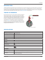
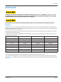
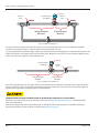
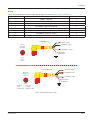
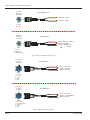
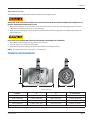
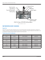
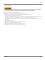
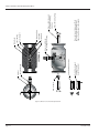
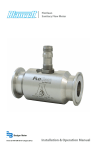
Turbine Flow Meter
FloClean Sanitary Turbine Flow Meter
TUR-UM-00288-EN-01 (November 2013)
User Manual
Turbine Flow Meter, FloClean Sanitary Flow Meter
Page ii
November 2013
User Manual
CONTENTS
INTRODUCTION . . . . . . . . . . . . . . . . . . . . . . . . . . . . . . . . . . . . . . . . . . . . . . . . . . . . . . . . . . . . . . . . . . . . . . .5
THEORY OF OPERATION . . . . . . . . . . . . . . . . . . . . . . . . . . . . . . . . . . . . . . . . . . . . . . . . . . . . . . . . . . . . . . . . . .5
SPECIFICATIONS . . . . . . . . . . . . . . . . . . . . . . . . . . . . . . . . . . . . . . . . . . . . . . . . . . . . . . . . . . . . . . . . . . . . . . .5
MODEL NUMBERS . . . . . . . . . . . . . . . . . . . . . . . . . . . . . . . . . . . . . . . . . . . . . . . . . . . . . . . . . . . . . . . . . . . . . .6
FloClean Flow Rate Chart . . . . . . . . . . . . . . . . . . . . . . . . . . . . . . . . . . . . . . . . . . . . . . . . . . . . . . . . . . . . . . 6
INSTALLATION . . . . . . . . . . . . . . . . . . . . . . . . . . . . . . . . . . . . . . . . . . . . . . . . . . . . . . . . . . . . . . . . . . . . . . . .7
Plumbing . . . . . . . . . . . . . . . . . . . . . . . . . . . . . . . . . . . . . . . . . . . . . . . . . . . . . . . . . . . . . . . . . . . . . . . . 7
Wiring . . . . . . . . . . . . . . . . . . . . . . . . . . . . . . . . . . . . . . . . . . . . . . . . . . . . . . . . . . . . . . . . . . . . . . . . . . 9
Operational Startup . . . . . . . . . . . . . . . . . . . . . . . . . . . . . . . . . . . . . . . . . . . . . . . . . . . . . . . . . . . . . . . . . 11
DIMENSIONS/DRAWINGS . . . . . . . . . . . . . . . . . . . . . . . . . . . . . . . . . . . . . . . . . . . . . . . . . . . . . . . . . . . . . . . . 11
METER REPAIR AND CLEANING . . . . . . . . . . . . . . . . . . . . . . . . . . . . . . . . . . . . . . . . . . . . . . . . . . . . . . . . . . . . 12
Repair Kits . . . . . . . . . . . . . . . . . . . . . . . . . . . . . . . . . . . . . . . . . . . . . . . . . . . . . . . . . . . . . . . . . . . . . . . 12
Turbine Repair Kits Part Numbers . . . . . . . . . . . . . . . . . . . . . . . . . . . . . . . . . . . . . . . . . . . . . . . . . . . . . . . . 12
Service Procedures . . . . . . . . . . . . . . . . . . . . . . . . . . . . . . . . . . . . . . . . . . . . . . . . . . . . . . . . . . . . . . . . . 13
B16C SERIES (COP/SOP) – 3-A TURBINE INSTALLATION . . . . . . . . . . . . . . . . . . . . . . . . . . . . . . . . . . . . . . . . . . . . . 15
TROUBLESHOOTING GUIDE . . . . . . . . . . . . . . . . . . . . . . . . . . . . . . . . . . . . . . . . . . . . . . . . . . . . . . . . . . . . . . . 16
3-A CERTIFICATE . . . . . . . . . . . . . . . . . . . . . . . . . . . . . . . . . . . . . . . . . . . . . . . . . . . . . . . . . . . . . . . . . . . . . . 17
November 2013
Page iii
Turbine Flow Meter, FloClean Sanitary Flow Meter
Page iv
November 2013
User Manual
INTRODUCTION
The Blancett FloClean turbine flow meter is designed with wear resistant moving parts to provide trouble-free operation and
long service life. The durable 316L stainless steel construction provides a cost efficient flow measurement system that offers
excellent accuracy and repeatability. The FloClean turbine meter repair kit is designed for easy field service of a damaged flow
meter, rather than replacing the entire flow meter. See Repair Kits on page 12 for information.
THEORY OF OPERATION
Fluid entering the meter passes through the inlet flow straightener
which reduces its turbulent flow pattern and improves the fluid’s
velocity profile. Fluid then passes through the turbine, causing it to
rotate at a speed proportional to the fluid velocity. As each turbine
blade passes through the magnetic field, the blade generates an
AC voltage pulse in the pickup coil at the base of the magnetic
pickup (see Figure 1). These pulses produce an output frequency
proportional to the volumetric flow through the meter. The output
frequency represents flow rate and/or totalization of fluid passing
through the turbine flow meter.
Output Signal
Magnetic
Pickup
Rotor
Figure 1: Theory of operation
SPECIFICATIONS
Physical
Body/Internal Wetted Parts
316L stainless steel.
Bearings
Nickel bindery tungsten carbide.
Turbine
Nickel plated CD4MCU stainless steel.
Shaft
Nickel bindery tungsten carbide.
Connections
Sanitary clamp ends.
Electrical
Pickup (option 0)
NEMA 6; –150…300° F (–100…149° C).
Accuracy
Accuracy
±1% of reading.
Repeatability
±0.1%.
Certifications
Construction
Temperature
–150…300° F (–101…149° C).
Pressure Rating
1000 psi maximum (rating based on Tri-Clamp sanitary connection).
Corrosion
Contact Blancett to determine if operating liquid is compatible with
materials of construction.
November 2013
Page 5
Turbine Flow Meter, FloClean Sanitary Flow Meter
MODEL NUMBERS
B 16 C - X
X
Bearing Material
A - Ni Bindery
Tungsten
Carbide
Sanitary Rating
C - COP/SOP (3A Compliant)
Ferrule Size
0 - 0.984 in.
1 - 1.984 in.
2 - 3.047 in.
2
X
X
Calibration
A - 5 Point (std)
B - 10 Point
C - 20 Point
Meter Body Hub
A - With Hub ¹
B - No Hub
Pickup Option
0 - NEMA 6 - Magnetic
1 - NEMA 6 - Mag
2 - Non NEMA 6 - Magnetic ²
3 - Non NEMA 6 - Mag
²
4 - Non NEMA 6 - Active 4...20 mA² - (B220-950)
6 - Non NEMA 6 - High Temperature ²
8 - Non NEMA 6 - Active 0...5V DC ² - (B220-951)
9 - None
Meter Size - Flow Range
03 - 0.6 - 3.0 gpm
05 - 0.75 - 7.50 gpm
07 - 2.0 - 15.0 gpm
08 - 3.0 - 30.0 gpm
10 - 5.0 - 50.0 gpm
15 - 15.0 - 180.0 gpm
20 - 40.0 - 400.0 gpm
1
X A - X
1/2 in. hub for body size 0; 1 in. hub for body sizes 1 and 2.
Indoor use only.
Figure 2: Model construction schema
FloClean Flow Rate Chart
Ferrule Size
Flow Ranges
gpm
lpm
K factor
Pulses/Gal
0.984 in.
0.6…3.0
2.3…11.4
20,000
0.984 in.
0.75…7.5
2.8…28.4
13,000
0.984 in.
2.0…15.0
7.5…56.8
2750
1.984 in.
0.75…7.5
2.8…28.4
13,000
1.984 in.
2.0…15.0
7.5…56.8
2750
1.984 in.
3.0…30.0
11.4…113.5
2686
1.984 in.
5.0…50.0
19.0…190.0
870
1.984 in.
15.0…180.0
56.8…681.4
330
3.047 in.
40.0…400.0
151.4…1514.2
52
Table 1: FloClean flow rates
Page 6
November 2013
User Manual
INSTALLATION
THE METER SHOULD NOT BE SUBJECTED TO TEMPERATURES ABOVE 300° F (149° C), OR BELOW –150° F (–101° C) OR
THE FREEZING POINT OF THE METERED LIQUID. HIGH TEMPERATURES WILL DAMAGE THE MAGNETIC PICKUP, WHILE
LOWER TEMPERATURES WILL LIMIT THE ROTATION OF THE ROTOR.
INCOMPATIBLE FLUIDS COULD DETERIORATE INTERNAL PARTS AND CAUSE THE METER TO READ INACCURATELY.
Plumbing
The flow meter must be installed with the flow arrow, etched on the exterior of the meter body, pointing in the direction of
fluid flow. Though the meter is designed to function in any position, it is recommended, where possible, to install horizontally
with the magnetic pickup facing upward.
The liquid being measured must be free of any large particles that may obstruct spinning of the rotor. If particles are present,
a mesh strainer should be installed.
If small particles are present in the fluid, Blancett recommends that a strainer be installed upstream of the meter. See Table 2
for filtration recommendations.
Bore Size
Ferrule Size
Strainer Size
Clearance
3/8 in.
0.984 in.
60 × 60
0.0092 in.
1/2 in.
0.984 in.
60 × 60
0.0092 in.
3/4 in.
0.984 in.
60 × 60
0.0092 in.
1/2 in.
1.984 in.
60 × 60
0.0090 in.
3/4 in.
1.984 in.
60 × 60
0.0092 in.
7/8 in.
1.984 in.
60 × 60
0.0092 in.
1 in.
1.984 in.
60 × 60
0.0092 in.
1-1/2 in.
1.984 in.
20 × 20
0.0340 in.
2 in.
3.047 in.
10 × 10
0.0650 in.
Table 2: Filtration recommendations
Severe pulsation and mechanical vibration will affect accuracy and shorten the life of the meter.
The preferred plumbing setup is one containing a bypass line that allows meter inspection and repair without interrupting
flow. See Figure 3. If a bypass line is not utilized, it is important that all control valves be located downstream of the flow meter.
See Figure 4.
November 2013
Page 7
Turbine Flow Meter, FloClean Sanitary Flow Meter
Display
1
Isolation
Valve
2
FloClean Turbine
Flow Meter
Isolation
Valve
10 Pipe Diameters
Minimum
5 Pipe Diameters
Minimum
Bypass Line
Figure 3: Installation with bypass line
This is true with any restriction in the flow line that may cause the liquid to flash. If necessary, air eliminators should be
installed to ensure that the meter is not incorrectly measuring entrained air or gas.
It is recommended that a minimum length, equal to ten (10) pipe diameters of straight pipe, be installed on the upstream side
and five (5) diameters on the downstream side of the flow meter. Otherwise, meter accuracy may be affected. Piping should
be the same size as the meter bore or threaded port size.
Display
1
FloClean Turbine
Flow Meter
10 Pipe Diameters
Minimum
2
Isolation
Valve
5 Pipe Diameters
Minimum
Figure 4: Installation without a bypass line
Do not locate the flow meter or connection cable close to electric motors, transformers, sparking devices, high voltage lines,
or place connecting cable in conduit with wires furnishing power for such devices. These devices can induce false signals in
the flow meter coil or cable causing the meter to read inaccurately.
DAMAGE CAN BE CAUSED BY STRIKING AN EMPTY METER WITH A HIGH VELOCITY FLOW STREAM.
If problems arise with the flow meter and monitor, consult the TROUBLESHOOTING GUIDE on page 16. If further problems
arise, consult the factory.
If the internal components of the turbine flow meter are damaged, turbine meter repair kits are available. Information
pertaining to the turbine meter repair kits is referenced in Repair Kits on page 12.
Page 8
November 2013
User Manual
Wiring
Typical wiring configurations for the available pickup options are shown in Figure 5, Figure 6, and Figure 7.
Option Number
Description
Number of Pins
0
NEMA 6 – Magnetic
3
1
NEMA 6 – Magnetic (Amplified)
3
2
Non-NEMA 6 – Magnetic
2
3
Non-NEMA 6 – Magnetic (Amplified)
3
4
Non-NEMA 6 – Active (4…20 mA)
5
6
Non-NEMA 6 – Magnetic (High Temperature)
2
8
Non-NEMA 6 – Active (0…5V DC)
5
No Pickup
N/A
9
Table 3: Pickup options
Pickup Option 0
1 - Green = Signal
2 - Red/Black = Signal
Standard
Mag Pickup
(Socket End)
3 - Red/White = Unused
Braided Shield to
Earth Ground
Pins
1. Signal
2. Signal
3. Unused
Pickup Option 1
1 - Green = Common
2 - Red/Black = Power
Mag Pickup
With Pre-Amp
(Socket End)
3 - Red/White = Signal
Braided Shield to
Earth Ground
Pins
1. Common:
2. Power:
3. Output Signal:
Power return
12…24 Vdc
10V DC Square Wave
Figure 5: Wiring for NEMA 6 magnetic pickups
November 2013
Page 9
Turbine Flow Meter, FloClean Sanitary Flow Meter
Standard
Mag Pickup
(Socket End)
Pickup Option 2 & 6
B - Yellow (-) = Signal
B
A
A - Blue (+) = Signal
Pins
A = Signal
B = Signal
Amplified
Mag Pickup
(Socket End)
C
Pickup Option 3
A - Red = Power (5…30V DC)
B - Black = Common
C - Green = Output Pulse
or
(0…10V DC)
Clear
A
B
Pins
A = Power
B = Common
C = Output Signal
Figure 6: Wiring for non-NEMA 6 magnetic pickups
Active Sensor
4...20 mA
(Socket End)
Pickup Option 4
3
4
2
5
1
1 - Red = +4...20 mA
2 - Black = -4...20 mA
3 - White = Not Used
Pins
1 = Loop (+)
2 = Loop (-)
3 = N/C
4 = N/C
5 = N/C
Active Sensor
0...5V DC
(Socket End)
Pickup Option 8
3
4
2
5
1
1 - Red = 10...30V DC
2 - Black = 0...5V DC Output
3 - White = Ground
Pins
1 = 10...30V DC
2 = 0...5V DC Output
3 = Ground
4 = N/C
5 = N/C
Figure 7: Wiring for active magnetic pickups
Page 10
November 2013
User Manual
Operational Startup
The following steps should be followed when installing and starting the meter.
MAKE SURE THAT FLUID FLOW HAS BEEN SHUT OFF AND PRESSURE IN THE LINE RELEASED BEFORE ATTEMPTING TO
INSTALL THE METER IN AN EXISTING SYSTEM.
1. After meter installation, close the isolation valves and open the bypass valve. Flow liquid through the bypass valve for
sufficient time to eliminate any air or gas in the flow line.
2. Open upstream isolating valve slowly to eliminate hydraulic shock while charging the meter with the liquid. Open the
valve to full open.
HIGH VELOCITY AIR OR GAS MAY DAMAGE THE INTERNAL COMPONENTS OF THE METER.
3. Open downstream isolating valve to permit meter to operate.
4. Close the bypass valve to a full closed position.
5. Adjust the downstream valve to provide the required flow rate through the meter.
NNOTE: The downstream valve may be used as a control valve.
DIMENSIONS/DRAWINGS
C
Stnd. #28-04 Auth. #956
A
B
Figure 8: Dimensions
Part No.
A
B
C – Ferrule Size
B16C-0XXA-XXX
3.00 in. (76.2 mm)
1.46 in. (37.1 mm)
0.984 in. (25.0 mm)
B16C-1XXA-XXX
4.00 in. (101.6 mm)
2.00 in. (50.8 mm)
1.984 in. (50.4 mm)
B16C-1XXA-XXX ¹
6.25 in. (158.8 mm)
2.33 in. (59.2 mm)
1.984 in. (50.4 mm)
B16C-2XXA-XXX
6.50 in. (165.1 mm)
3.20 in. (81.3 mm)
3.047 in. (77.4 mm)
¹ 15.0…180.0 gpm flow range only.
Table 4: Dimensions
November 2013
Page 11
Turbine Flow Meter, FloClean Sanitary Flow Meter
Rotor Assembly
Magnetic Pickup
Jam Nut
Sleeve Bearing
Meter Body
Rotor Support
Thrust Ball (Removable)
Retaining Ring
Stnd. #28-04 Auth. #956
Manufacturer’s Label
and 3-A Symbol
B16C 3-A Series (COP/SOP) FloClean Meters
Figure 9: FloClean cross sections
METER REPAIR AND CLEANING
Repair Kits
Each FloClean repair kit is factory calibrated to ensure accuracy throughout the entire flow range. Each kit is complete and
includes a new K factor, which is the calibrated number of pulses generated by each gallon of liquid. This K factor will be used
to recalibrate the monitor or other electronics to provide accurate output data.
Turbine Repair Kits Part Numbers
Bore Size
Ferrule Size
Repair Kit Fits Meter Part Number
Repair Kit Part Number
3/8 in.
0.984 in.
B16C-003A-XXX
B16C-K03A
1/2 in.
0.984 in.
B16C-005A-XXX
B16C-K05A
3/4 in.
0.984 in.
B16C-007A-XXX
B16C-K07A
1/2 in.
1.984 in.
B16C-105A-XXX
B16C-K05A
3/4 in.
1.984 in.
B16C-107A-XXX
B16C-K07A
7/8 in.
1.984 in.
B16C-108A-XXX
B16C-K08A
1 in.
1.984 in.
B16C-110A-XXX
B16C-K10A
1-1/2 in.
1.984 in.
B16C-115A-XXX
B16C-K15A
2 in.
3.047 in.
B16C-220A-XXX
B16C-K20A
Table 5: B16C 3-A series (COP/SOP) FloClean meters
Page 12
November 2013
User Manual
Service Procedures
HIGH-PRESSURE LEAKS ARE DANGEROUS AND CAUSE PERSONAL INJURY. MAKE SURE THAT FLUID FLOW HAS BEEN
SHUT OFF AND PRESSURE IN THE LINE RELEASED BEFORE ATTEMPTING TO REMOVE THE METER.
3-A Turbine Disassembly and Cleaning Procedure
NNOTE: Refer to Figure 10 for relative positions of repair kit components.
1. Remove the magnetic pickup from the meter body to avoid damage during procedure.
2. Remove the retaining ring from one end of the meter.
3. Keeping the meter upright (pickup port at the top), remove the rotor support from the body, taking care not to rotate it in
the process. If the rotor support is jammed in the body, use a pair of pliers or vice grips to break it free.
4. Hold the rotor support over a suitable container and rotate it through 180°. The thrust ball will drop out. Take care not to
lose the ball.
5. Remove the rotor assembly.
6. Remove the second retaining ring from the opposite side of the meter.
7. Repeat steps 3 and 4 for the remaining rotor support.
8. Identify parts and flow direction to match with original meter body.
9. Clean and/or sanitize parts to meet appropriate sanitary standards.
November 2013
Page 13
Page 14
A
A
Remove Rotor
Stnd. #28-04 Auth. #956
SECTION A-A
Rotate Rotor Support
Through 180° To
Extract Thrust Ball
Thrust Ball Extraction Hole
Magnetic Pickup
Jam Nut
Remove Retaining Rings
Remove Rotor Supports
Do Not Rotate During
Extraction
Clean and Inspect Component Parts
Per 3-A Sanitary Standards; Reverse
Dismantling Procedure to Reassemble
Release Jam Nut and
Remove Magnetic Pickup
Thrust Ball
Rotor Assembly
Retaining Ring
Rotor Support
Sleeve Bearing
Meter Body
Turbine Flow Meter, FloClean Sanitary Flow Meter
Figure 10: B16C 3-A series FloClean exploded view
November 2013
User Manual
B16C SERIES (COP/SOP) – 3-A TURBINE INSTALLATION
NNOTE: This procedure applies to installation of replacement turbine repair kits and re-installation of cleaned or
sanitized turbine.
IIMPORTAN
Before reassembly, note there are weep holes on each rotor support. These weep holes must be facing down toward the bottom of
the meter body when installed.
The meter must be reassembled with the arrowheads on the rotor pointed in the direction of fluid flow. The magnetic pickup
side of the body signifies the up position. This is the position that the repair kit was calibrated, and this is the position to be
used to ensure meter accuracy. Due to the polished surfaces, there are no arrows on the rotor support to indicate which rotor
support is to be placed upstream or downstream. Please install the repair kit as it was received in the box, using the arrow on
the rotor to determine the placement of the rotor support.
1. If required by process procedures, the meter should be cleaned prior to installation into the piping system.
2. Drop a thrust ball into a rotor support through the hole provided in the side. Insert rotor support into the meter body.
Keep the thrust bearing hole pointed upwards to keep the ball in place.
3. Secure a retaining ring in the groove provided. Be sure that the retaining ring is completely installed in the groove.
4. Drop a thrust ball into second rotor support through the hole provided in the side. Locate the rotor in the support sleeve
bearing. Insert rotor support and rotor into the meter body and the first support sleeve bearing. Keep the thrust bearing
hole pointed upwards to keep the ball in place.
5. Secure the second retaining ring in the groove provided. Be sure that the retaining ring is completely installed in
the groove.
EXCESS AIR PRESSURE MAY DAMAGE THE ROTOR AND BEARINGS BY OVER-SPIN.
6. Check the meter by blowing air through the assembly. If the rotor does not turn freely, the meter should be disassembled
and checked for anything that would obstruct movement of the rotor.
7. Install the magnetic pickup.
NNOTE: After installing the new repair kit, the electronics will need re-calibration. Refer to the electronics’ installation and
operation manual. If there are any questions on re-calibration, contact Blancett at 1.800.235.1638 or contact the
manufacturer of the associated electronics.
November 2013
Page 15
Turbine Flow Meter, FloClean Sanitary Flow Meter
TROUBLESHOOTING GUIDE
Trouble
Possible Cause
Remedy
Meter indicates higher than actual
flow rate
• Cavitation
• Debris on rotor support
• Build up of foreign material on
meter bore
• Gas in liquid
•
•
•
•
Increase back pressure
Clean meter
Clean meter
Install gas eliminator ahead of meter
Meter indicates lower than actual
flow rate
• Debris on rotor
• Worn bearing
• Viscosity higher than calibrated
• Clean meter and add filter
• Install new repair kit
• Recalibrate monitor
Erratic system indication, meter
alone works well (remote monitor
application only)
Ground loop in shielding
Ground shield one place only. Look for
internal electronic instrument ground.
Reroute cables away from electrical noise.
Indicator shows flow when shut off
Mechanical vibration causes rotor to
oscillate without turning
Isolate meter
No flow indication, full or partial
open position
Fluid shock, full flow into dry meter or
impact caused bearing separation or
broken rotor shaft
Rebuild meter with repair kit and
recalibrate monitor. Move to location
where meter is full on startup or add
downstream flow control valve.
Erratic indication at low flow, good
indication at high flow
Rotor has foreign material wrapped
around it
Clean meter and add filter
No flow indication
Faulty pickup
Replace pickup
System works perfect, except
Bypass flow, leak
indicates lower flow over entire range
Repair or replace bypass valves or faulty
solenoid valves
Meter indicating high flow, upstream
piping at meter smaller than meter
bore
Fluid jet impingement on rotor
Change piping
Opposite effects of above
Viscosity lower than calibrated
Change temperature, change fluid or
recalibrate meter
Page 16
November 2013
User Manual
3-A CERTIFICATE
Initially Issued: 3/19/1998
Authorization No.: 956
This Is To Certify That
Blancett Division of Racine Federated, Inc.
8635 Washington Avenue, Racine, WI 53406
Is hereby authorized to continue to apply the 3-A Symbol to the models of equipment, conforming to
3-A Sanitary Standards for:
Flow Meters, Number: 28-04, set forth below:
B16C-003A-xxx, B16C-005A-xxx, B16C-007A-xxx, B16C-105A-xxx, B16C-107A-xxx,
B16C-108A-xxx, B16C-110A-xxx, B16C-115A-xxx, B16C-220A-xxx.
Valid through: December 31, 2012
Executive Director, 3-A Sanitary Standards, Inc.
*****
The issuance of this authorization for the use of the 3-A Symbol is based upon the voluntary
certification, by the applicant for it, that the equipment listed above complies fully with the 3-A
Sanitary Standards designated. Legal responsibility for compliance is solely that of the holder of this
Certificate of Authorization, and 3-A Sanitary Standards, Inc. does not warrant that the holder of an
authorization at all times complies with the provisions of the said 3-A Sanitary Standards. This in no
way affects the responsibility of 3-A Sanitary Standards, Inc. to take appropriate action in such cases
in which evidence of nonconformance has been established.
Next TPV Inspection/Report due: March 2016
Figure 11: 3-A Certificate
November 2013
Page 17
Turbine Flow Meter, FloClean Sanitary Flow Meter
INTENTIONAL BLANK PAGE
Page 18
November 2013
User Manual
INTENTIONAL BLANK PAGE
November 2013
Page 19
Blancett is a registered trademark of Badger Meter, Inc. Other trademarks appearing in this document are the property of their respective entities. Due to continuous research,
product improvements and enhancements, Badger Meter reserves the right to change product or system specifications without notice, except to the extent an outstanding
contractual obligation exists. © 2013 Badger Meter, Inc. All rights reserved.
www.badgermeter.com
The Americas | Badger Meter | 4545 West Brown Deer Rd | PO Box 245036 | Milwaukee, WI 53224-9536 | 800-876-3837 | 414-355-0400
México | Badger Meter de las Americas, S.A. de C.V. | Pedro Luis Ogazón N°32 | Esq. Angelina N°24 | Colonia Guadalupe Inn | CP 01050 | México, DF | México | +52-55-5662-0882
Europe, Middle East and Africa | Badger Meter Europa GmbH | Nurtinger Str 76 | 72639 Neuffen | Germany | +49-7025-9208-0
Czech Republic | Badger Meter Czech Republic s.r.o. | Maříkova 2082/26 | 621 00 Brno, Czech Republic | +420-5-41420411
Slovakia | Badger Meter Slovakia s.r.o. | Racianska 109/B | 831 02 Bratislava, Slovakia | +421-2-44 63 83 01
Asia Pacific | Badger Meter | 80 Marine Parade Rd | 21-04 Parkway Parade | Singapore 449269 | +65-63464836
China | Badger Meter | 7-1202 | 99 Hangzhong Road | Minhang District | Shanghai | China 201101 | +86-21-5763 5412
Legacy Document Number: 02-TUR-UM-00107