1
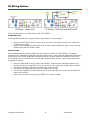
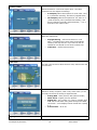
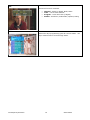
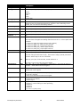
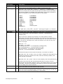
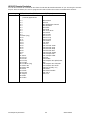
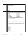
Product Manual ICC2-ATSC4 HDTV Tuner/Controller September 27, 2015 S12 Control Version 5.6 HD Processor Version 6.04 Contemporary Research 1 ICC2-ATSC4 Table of Contents Overview ................................................................................................................................................................. 3 Specifications .......................................................................................................................................................... 4 Physical .................................................................................................................................................................. 4 Front Panel ............................................................................................................................................................. 4 Rear Panel .............................................................................................................................................................. 4 Tuning ................................................................................................................................................................... 5 Includes ................................................................................................................................................................. 5 Options .................................................................................................................................................................. 5 Trademarks ............................................................................................................................................................ 5 Troubleshooting ...................................................................................................................................................... 6 RF Wiring Options ................................................................................................................................................... 8 Setup Guide ............................................................................................................................................................. 9 IR Remote Operation ............................................................................................................................................... 9 Front Panel Setup ................................................................................................................................................. 10 On-Screen Menus (IC Mode) ................................................................................................................................ 11 RS-232 Control Codes ........................................................................................................................................... 12 Input Selects ......................................................................................................................................................... 12 Input Command ..................................................................................................................................................... 12 On-Screen Menus (HD2 Mode) ............................................................................................................................. 14 Main Menu ............................................................................................................................................................ 14 Channel Menus ...................................................................................................................................................... 14 Caption Menus ....................................................................................................................................................... 16 V-Chip Settings Menus ............................................................................................................................................ 16 Setup Menus ......................................................................................................................................................... 17 Pop-Up Menus ....................................................................................................................................................... 18 IC-Net Control Protocol ........................................................................................................................................ 20 Overview ............................................................................................................................................................... 20 Command String Structure ...................................................................................................................................... 20 IC-Net Commands................................................................................................................................................. 21 Control .................................................................................................................................................................. 21 Tuning .................................................................................................................................................................. 22 Tuning .................................................................................................................................................................. 23 Text ...................................................................................................................................................................... 23 HD2-RC Remote Emulation ..................................................................................................................................... 24 Rack Mounting ...................................................................................................................................................... 26 iC-Net Zones, Units and Device Addresses........................................................................................................... 27 System Map ........................................................................................................................................................... 28 Safety Instructions ............................................................................................................................................... 29 Limited Warranty .................................................................................................................................................. 30 Contemporary Research 2 ICC2-ATSC4 Overview The ICC2-ATSC 4 HDTV Tuner includes all the proven performance of the previous ICC2-ATSC+, plus added features from the 232-ATSC 4 tuner. Receives MPEG4 and MPEG2 programs Outputs up to 1080p video The ICC2-ATSC 4 HDTV Tuner is an integrated HDTV tuner/controller that networks HD display monitors and projectors in a Display Express control system. As a universal TV tuner, the ICC2-ATSC 4 can receive ATSC, NTSC, and clear QAM cable channels from an MATV antenna or CATV cable RF system. The tuner displays broadcasts through simultaneous HDMI and NTSC composite ports and switched HD RGBHV or Component outputs. Full-time audio is available from digital Dolby 5.1/PCM/Variable PCM HDMI, optical, and coax ports, as well as variable-level analog stereo audio outputs. Integrated Display Control - Employs RS-232 control port for integrated display or video projector control, includes onboard database of display control command Through-the-RF Coax Networking - Communicates with Display Express Web software, and custom control systems via iC-Net RF protocol Universal Tuning – Handles a mix of ATSC, clear QAM (MPEG and MPEG4) and NTSC channels, cable or off-air tuning Pro Integration - Features 2-way RS-232 control and feedback with simple ASCII commands, as well as discrete IR and wired IR - AMX and Crestron modules available Fast Tuning - Changes analog and digital channels instantly with improved RF reception Total Video - Simultaneous HDMI and composite video, switchable RGBHV or Component HD video Total Audio - Simultaneous digital Dolby 5.1/PCM/Variable PCM HDMI, coax, and optical outputs, as well as variable-level analog stereo HD Scaling - Upscales HD output up to 1080p Easy Set-up - Front-panel programming supported by LCD display, on-screen menus using HD2-RC IR remote (included), and RS-232 control commands Closed Captioning - Displays analog and digital captioning text On-Screen Menus - Setup, Electronic Program Guide, Channel, Favorites, and Program Information menus Compact Rack Mounting - Mounts in 2RU single RK1-HD or dual RK2-HD 19” rack kits Includes - 12 VDC switching power supply Options – HD2-RC wireless remote, RK1-HD and RK2-HD rack kits, CC-232 or CC-COM RS-232 control cables, IR-RXC External IR Receiver Green Machine - Meets RoHS safety and California energy standards Field Updatable – download new control and HD processor firmware from CR website Contemporary Research 3 ICC2-ATSC4 Specifications Physical Size (HWD): 8.5” [216mm] wide x 2.0” [51mm] height (1.5 RU) x 8.0” [203mm] deep Weight: 1.94 lbs [890 g] Enclosure: Steel with black powder coat paint Mounting: 2/1.5RU Rack mounting for one or two units side-by-side optional (RK1/2-HD+, RK1S/RK2S-HD+) Front Panel Display: Red LED Channel Display, dot separated major and minor channel numbers, dot at end indicates Off-Air tuning IR: IR sensor Control: Power, Menu, and Select buttons, navigation using Up and Down (Channel Up and Down) buttons Left and Right (Volume Down and Up) buttons LEDs: RS-232 RX (Yellow), RS-232 TX (Red), Net (Green – flashes every second to confirm iC-Net control signal) Rear Panel Service: USB port (not active presently) RF In: Air/Cable, ‘F’, female, 75 ohm impedance, -10 to 15 dBmV typical, receives RF control channel RF Out: ‘F’, female, Passes RF channels to Air/Cable input, cable included Air/Cable: ‘F’, female, 75 ohm impedance, -10 to 15 dBmV typical A/C Jack: 3.5mm jack for RF-AB Air/Cable Switch Video Output: Simultaneous HDM and NTSC video, switch between RGB and Component Video Out: RCA composite video output, 1V p-p at 75 ohm impedance, 480i Component Out: 3 RCA Y, Pr, Pb outputs (1080p/1080i/720p/480p/480i) RGB Out: RGBHV DB-15 female (1080p/1080i/720p/480p, 59.95 Hz) HDMI: HDMI receptacle, Type A, HD video and digital audio, version 1.3 (1080p/1080i/720p/480p) Use PCM mode if HDMI audio connection is used to most displays (not all have Dolby) Audio Output: Simultaneous HDMI, Coax, Optical, and Stereo Digital Audio SPDIF: Coax and TOSlink optical output, Dolby 5.1 AC3/PCM/Variable PCM Analog Audio Out: Stereo RCA audio, Mono, Stereo, or SAP, variable level RS-232 Control: DB-9 male, RS-232 data link to control system or PC, up to 9 tuners, 300-19,200 baud IR In: 3.5mm stereo jack for optional IR-RXC IR Receiver Sleeve= DC power+ from power jack input, limited to less than 100mA Ring=DC power– (GND) Tip= IR data signal Power In: 2.1mm coaxial jack (inside center conductor positive) 1.1 A maximum, 11.5 to 15 VDC, 12 VDC typical Contemporary Research 4 ICC2-ATSC4 Tuning Frequency Range: ATSC and Clear QAM (cable) television 55.25 to 801.25 MHz TV System: ATSC, NTSC, Cable, and Clear QAM (1080i/720p/480p/480i) Tuning: Off-air 14-69 (NTSC and 8-VSB) and CATV 1-135 (Analog, 64QAM, 256QAM, 8-VSB) Aspect Ratio: 4:3, 16:9 (Digital), 4:3, 16:9, Zoom (Analog channels) Captioning: DTV and analog, set by program or customized for size, font and display attributes Captioning Data: HDMI, RGB, and Component ports don’t have the ability to carry captioning data. The composite video port will carry Line 21 data, but only when tuned to an analog channel Lock: Parental option for channels and/or rating Includes Compact Power Supply, 1.5A maximum, 12 VDC RF Loop Cable for connection of RF Out to Air/Cable input Options RK1-HD+ Single Rack Kit, 2RU RK2-HD+ Dual Rack Kit, 2RU RK1S-HD+ Single Space-Saver Rack, 1.5RU (reverse mount to stack) RK2S-HD+ Dual Space-Saver Rack, 1.5RU (reverse mount to stack) PMT-2+ Pole Mount Bracket RF-AB RF A-B Switch, self-terminating, closure controlled (if system has dual Air and Cable feeds) IR-RXC External IR Receiver CC-COM or CC-232 RS-232 Control Cable Firmware HD V3.05 Provides Line captioning data on Composite video from analog and digital channels, tuner stays on sub-channel with program data is lost, does not change to default N.1 channel. SF V5.1 This adapts commands to operate with a new series tuner board. Trademarks VGA and XGA are trademarks of International Business Machines SVGA is a trademark of the Video Electronics Standard Association HDMI, the HDMI logo and High-Definition Multimedia Interface are trademarks or registered trademarks of HDMI Licensing LLC. Manufactured under license from Dolby Laboratories, Dolby and the double-D symbol are trademarks of Laboratories Contemporary Research 5 ICC2-ATSC4 Troubleshooting TUNING CABLE CHANNELS Tip: The 232-ATSC+ will skip encrypted channels automatically when you activate a channel scan Tip: You can skip scanning analog channels by pressing Select after you start the scan. Symptom: Channel ID is in XX-XX form, not cable box Guide form Cable boxes translate the actual channel #s into a virtual Channel Guide, using channels 2 – 900, or more. The actual (physical) channels have IDs in XXX-XX form, just like off-air channels. Noncable HDTV tuners like the ATSC or LCD TVs don’t provide Guide features, so the channels will be displayed in their native, physical major-minor channel form. Some cable franchisees have a listing by physical channel, many do not. You can press the INFO button on the HD2-RC remote to view the channel name. POWER/VIDEO OUTPUT Symptom: Tuner appears to be on, channel display is lit, but unresponsive, no video/audio out This often occurs when a 232-ATSC+ is used to replace an old 232-series analog tuner. The solution is to not use the old 500 Ma power supply, and use the 1.5 Amp power supply that comes with the ATSC. The old supply has enough juice to light up the front panel LEDs, but nothing else. Symptom: No video on Component Out The RGB and Component outputs are switchable, and the tuner ships set to RGB. Use Front Panel Mode, next section to switch the HD analog video to Component. HDMI Symptom: No Video or Signal Most monitors accept HDMI in the RGB and Component color space, but there are exceptions. Try switching from RGB to Component (Front panel mode 48). Switch between 720p and 1080i, or down to 480P or 480i for old DVI sets. (Front panel mode 49) If you’re connecting via a Cat5 interface, HDMI receiver, or switcher, some delay the HDCP signal slightly out of range. Call CR Support on how to extend the delay on HDMI. Symptom: No audio or fluttering sound in display speakers connected via HDMI Change ATSC digital audio to PCM or PCM variable (most displays do not use Dolby 5.1) RGB/Component Symptom: No RGB or Component Video output Check the RGB or Component output setting in Front Panel mode 48 (48.0 is RGB, 48.2 is Component). Symptom: No output display on VGA input Some monitors or projectors do not support 1080i or 720P operation on the RGB port. Set resolution in Front Panel mode 49 (49.2 for 480P). Composite Video Symptom: Composite video out has small image in 16:9 setting, analog channels For a 4:3 set, tune to an analog channel and press RATIO on the remote to set to 16:9. Image will fill left to right, you’ll always have a black band top and bottom. Set to 4:3 if you’re only feeding video to 4:3 TVs. Set output ratio on a digital channel as well - this a different setting than for analog channels. If the tuner is used for 16:9 displays and analog TVs, choose the best setting for the widescreen, and the NTSC will have to be a compromise. Most of the time, setting the RATIO while tuned to an analog channel and again for a digital channel will provide the best result. Contemporary Research 6 ICC2-ATSC4 IR Control Symptom: IR remote won’t control tuner Hold down IR remote Select, press 9, and release both. Front-panel setting should be 15.9. In addition, check if the remote works when the lights are off. Some energy-saving fluorescent lights produce interference at our IR frequency (57 Hz). Try to cover the IR sensor so the lights don’t affect operation, or add the IR-RXC External IR Sensor. It’s easier to hide and tilt the sensor to help with reception, and you can try Select and 4 to use the lower IR frequency (the RXC has both types of sensors). Line 21 (analog) Captioning on Video Output Symptom: Video out does not include captioning The 232-ATSC+ does not carry forward closed captioning codes when tuned to an analog channel. However, all captioning from digital TV channels is converted to analog captioning on the video output. Contemporary Research 7 ICC2-ATSC4 RF Wiring Options There are two ways to wire RF feeds to the ICC2-ATSC+. Single RF Feed Most applications will use a single RF feed, either Cable or Air (Antenna). Connect the RF feed to RF In on the top of the tuner. This allows the tuner to receive the iC-Net control signal. Connect the included short RF cable from RF Out to the Air/Cable RF input. A low-loss tap feeds the RF feed the ATSC+ tuner. Dual RF Feed Other applications will use both Cable and Air (Antenna) feeds. The ICC2-ATSC 4 can switch between both, maintaining separate channels lists for each. You’ll need the optional RF-AB switch, which has a mini 3.5mm cable that connects to the A/C control output on the back of the tuner. The placement of RF connections on the RF-AB is different than shown – the RF ports above are arranged for clarity. Wire the Cable feed to the RF input of the ATSC+. Note that the Cable feed needs to go through the RF In on the ATSC+ first, so the tuner can receive the iC-Net control channel. Connect the ATSC+ RF Out to the Cable input of the RF-AB. Connect the Air/Antenna feed to the Air input of the RF-AB. Connect the included short RF cable to the RF-AB switch RF Out, then to the Air/Cable RF input on the ATSC+. Connect the 3.5mm mini plug to the ATSC+ A/C control output. Contemporary Research 8 ICC2-ATSC4 Setup Guide The ICC2-ATSC 4 supports a mix of setup tools, including: HD2-RC Remote Mode (accesses On-Screen Graphic Menus and special HD functions) IC-RC Remote Mode (accesses Text Menus and special media functions) Front-Panel Setup IC-Net commands from system or iC Send The reason for the options is that the ICC2-ATSC 4 is designed to offer advanced analog/digital tuning, yet be compatible with existing iC-Net systems. IR Remote Operation The IC-RC Remote is used with analog tuners as well as media and text menu control functions when used in iC-Net control systems. The HD2-RC IR Remote is designed for control and setup of ATSC-series HDTV tuners. Both remotes send the same IR codes, the difference is in how the tuner responds. In most cases, IC-Net systems, especially for schools and other applications that access onscreen text menus and interactive media control, will continue to use the traditional IC-RC remote and mode. System integrators can switch the ICC2-ATSC 4 to the HD2-RC mode to access HD features, such as channel scans and set up of 16:9 or 4:3 display modes. Then switch to IC mode to test iC-net operation and IC-Net device number. Front-Panel Setup The Front Panel modes are useful for setting tune mode, HD output and resolution, and switching between IC and HD2 remote modes. IC Send Control You’ll find the free IC Send program to be a great tool for system setup and testing, especially if the site is using the ICE-HE Head End and your laptop is configured for the site’s network. You can also use a PC or laptop via RS-232 with the ICC-HE Head End. Key functions include: On, Off and Tune commands to test operation to one or all ICC2-ATSC 4 units. IR Mode. Switch all tuners to IC or HD2 modes. Channel Setup. Use the T^ Command to force all units to scan channels, then use the XA and XD commands to add and remove channels from the list. If you’re using RS-232 control at the head end, have an ICC2-ATSC 4 at that location to check your setup. Tuner Setup. Use LM and TM commands to configure general tuner operation. Default Input. Use the ER command to set the default input. Device Address Settings Use the front-panel setting 2 and 3 to set the address. Menu 3 sets the Zone address, and Menu 2 sets the individual number in the zone. For example the system address for a controller is 257, set Menu 2 to 2.1 (1), and Menu 3 to 3.1 (Zone 1, which is address 256), 1 + 256 = 257 system address. The controller will act by itself when you send the unique 257 code, as a zone group when you send 256, or with all with address 4095. Zone Zone 1 256 9 2 512 10 3 768 11 4 1024 12 5 1280 13 6 1536 14 7 8 1792 2048 2304 2560 2816 3072 3328 3584 3840 Contemporary Research 9 15 ICC2-ATSC4 Front Panel Setup To Enter a Front Panel Programming Mode: 1. Press and hold the Power button, then press the Volume Up button 2. Release all buttons, the ICC2-ATSC 4 will now be in the front-panel programming mode. The Air LED will flash, indicating programming mode. 3. The first two digits show the mode, the second show the option. 4. Changes are saved in non-volatile memory as they are entered. 5. The Volume up/down buttons scroll through programming modes, forward and reverse. 6. The Channel up/down buttons scroll through possible options for each mode. To Exit the Front Panel Mode Push and release the Power button. Mode RF Tune 0-9 0.0 Baud Rate 1.1 1.2 1.3 1.4 1.5 1.6 1.7 2.1 Unit Number Zone Number Panel Lockout Power-up Volume Firmware Version Captions 3.0 4.0 5.0 5.X 6.20 Video Detect AV Status Label Mode IR Receive Digital Captions IR Remote 10.0 10.1 11.1 11.2 11.3 11.4 11.X 12.3 13.0 14.2 15.9 17.1 18.1 Tune Control 19.0 Digital Audio 47.0 47.1 47.2 48.0 48.2 49.0 49.1 49.2 49.3 49.4 Caption Mode HD Output HD Format Contemporary Research Parameters 0=CATV (Default) 1=Off-Air 2=IRC 3=HRC 4=Cable Auto 300 600 1200 2400 4800 9600 19200 1-99 (The LCD can’t show a higher number. It's easier to use the Menu 999 function on the next page. Set IR Mode 18.1 to 18.0 to see the onscreen character generator. Once you’re at the device # menu, you can enter the unit’s address using the number keys on the IR remote.) 1-15 System device number is (Unit + (Zone * 256)) Reserved (performed by LM command) Restore previous level (default) 1 – 63 sets volume level Ex: Version 2.0 Press and hold Channel Up, then Power to restore tuner to default settings Press and hold Channel Up and Down, then Power to scan channels Captioning off (default) Captioning on 1=Caption 1 (default) 2=Caption 2 3=Caption 3 4=Caption 4 5-8= Text 1-4 (rarely used) No AV mute (fixed) No AV status (default) Numeric (fixed) 0= Off, 9=Receive IR 1-6, Default is 1 0=IC-RC 1=HD2-RC 0=Tune all channels 1= Only tune channels in List 0=AC-3– Dolby 5.1 1=PCM (set to this for audio through HDMI) 2=PCM Variable (default) RGB (Default) Component 0=1080i (Default) 1=720p 2=480p 3=480i 4=1080p 10 ICC2-ATSC4 On-Screen Menus (IC Mode) The remaining installation steps use the IR remote and the built-in character generator of the ICC2-ATSC+. 1. Change the IR Remote mode in front-panel menu 18 to IC-RC (18.0). This will enable the character generator to display the menus below. 2. Touch Menu, then 999, then Enter. 3. The text CR MENU> should appear on the screen. 4. Key in one of the commands shown below, then press Enter to activate. 5. Note that, in Menu mode, the Channel Down key acts as a backspace/delete key. Command Function 45678 Display firmware version 45679 Display the unit’s device #. At this point, you can use the Channel Down key as a Delete key, enter a new device # with the remote’s numeric keypad, then hit Enter to save the new number. 45700 Display current projector/monitor control commands. The code is installed by CR when the unit ships, codes can be changed over the RF. See RS-232 Control Codes on the next page. 45718 IR Remote Type 0=IC-RC 1=HD2-RC 45719 Tuning Control 45720 0=Tune all channels 1= Only tune channels in List Set Display/Projector Input Enter code 1-19. See page 23 in the ER section for input codes 65478 Reset controller, similar to disconnecting power then restarting. 65487 Initialize to factory default settings: Power on, unlocked, display channel 11, channel ring set to 4, 5, and 11, Group 0. Note that this command works even if TV power is off or control is locked out. 65480 Enable constant Net transmit to the Head-End. This is used for measuring the signal strength of the unit’s RF output. Press Enter to stop transmit or the unit will automatically stop after 50 seconds. 65481 Display DA transmitter frequency control voltage – should be 2000 - 3150. 65482 Display iCC-Net RF receive signal strength. Shows Net RX if receiving the iC-HE’s “heartbeat” pulse once per second, !NET RX if not. 65483 Display DF transmitter frequency deviation – should be 245 - 300 Contemporary Research 11 ICC2-ATSC4 RS-232 Control Codes The following chart includes the current control codes for TVs and projectors. We can add new command sets as needed. The ICC2-ATSC 4 is shipped pre-loaded with the specific RS-232 code. Units can be updated to different control code sets via the RF. MFG Type Full Operation LG Mitsubishi NEC 2 NEC 3 Projection Design Library Eiki Epson Christie InFocus Hitachi NEC 1 Optoma Panasonic Pioneer Samsung Sanyo Sharp Sony Sony Specialty Extron Notes Responds to 0-NNN TV command for inputs LCD VP LCD LCD VP Older M-series monitors New M, P, S, V, X series Responds to Input command, will be upgraded to full operation when needed VP VP VP VP VP Plasma VP LCD LCD LCD VP VP VP LCD WP Emulates Wall Panel buttons Input Selects The code sets listed in Full Operation above the list have the ability to select inputs from a special channel command, 0-NNN. For example, a 0-211 command would send the TV to the HDMI 1 input. For some makes, such as LG, you need to send a TV/Tuner command (0-200) to restore the TV to the current channel. For other sets, sending a channel command automatically selects the tuner if it’s at a different input. The command list covers all the possibilities, not all sets have every option. 115=Captions 200=TV/Tuner 201=Video1 202=Video2 203=Video3 204=S-Video1 205=S-Video2 206=Component1 207=Component2 208=RGB1 209=RGB2 210=RGB3 211=HDMI1 212=HDMI2 213=HDMI3 214=HDMI4 215=HDMI5 Input Command You will need to specify the default input for the ICC1-ATSC+, so that the unit will return to the correct input. You can use the 45700 menu command on page 11 to set the input, or use IC-Send or Display Express to send the ER command on page 23 to the tuner once it’s on the IC-Net RF network. Contemporary Research 12 ICC2-ATSC4 HD2-RC IR Remote The HD2-RC IR Remote can be used to setup the tuner and for daily operation. The IC-RC remote will work as well, the image below shows the function of the keys when the tuner is in the HD2-RC mode. Power Turns tuner on and off. Discrete on and off IR commands are available as well. Volume Control Use the Vol+, Vol- and Mute buttons. Channel Selection The key change in digital tuning is the need to add a dash (-) and number after the traditional channel number. Analog channels are accessed using XX-0, digital channels using XX-1 (or -2, -3, etc). Ch+, Ch- and PrevCh can be used to access and recall channels. Menu Operation Press Menu to access the on-screen menus. Use the directional Arrows, Select and Exit to navigate the menus. List displays the list of all channels, arrow keys add/remove channels, set Favorite Channel list Exit steps backwards out of menus Enter selects menu choice Special Functions CC steps through available closed-captioning options Audio selects audio and SAP modes Signal displays channel signal level Ratio steps through aspect ratios, options depend on channel and output types Info launches on-screen information window A/C selects Air or Cable tuning Fav Displays list of favorite channels Guide displays on-screen Guide Features of many of the Special Function commands depend on whether the current channel is analog or digital. Contemporary Research 13 ICC2-ATSC4 On-Screen Menus (HD2 Mode) Main Menu Selects sub-menus. Arrow keys highlight option Select (or Enter) chooses option Menu steps back or exits menus Exit exits all menus Some options are only available if you are currently tuned to an analog or digital channel Channel Menus Sub-Menu for Channels offers options for: Channel Auto-Scan Favorite Channel Selection Add/Delete Channels Fine Tune (If tuned to an analog channel) Signal Strength Meter Auto-Scan Starts scan of analog and digital channels for: Air – looks for NTSC and ATSC channels Cable Auto – looks for analog and digital QAM cable channels, as well as all frequency plans Cable STD - standard cable spacing Cable HRC – HRC cable spacing Cable IRC – IRC cable spacing Tip: Normally, use Auto. Most cable channels will be in standard frequencies. If all the channels tune in STD but channels 5 and 6, scan for IRC. If few channels can be found, scan for HRC. Contemporary Research 14 ICC2-ATSC4 Favorite Channels Menu is also displayed from the List command, selects channels advanced by the FAV favorite channel command. Use the Up, Down arrows to move through the list, press Select to add a channel to Favorites. Channel Add/Delete This menu can add or delete a channel accessed from Channel Up and Down. You can tune to a channel you want to delete, then press Menu/Channel/Add-Delete. Press Select to delete the channel. You can also keep the page on screen as you step through channels, adding and deleting as desired. If the channel has a good signal, it will be displayed in the background. Note that HDTV channels are broadcast on UHF frequencies. The Add/Delete will show the name of the digital channel, as well as the actual UHF channel used for broadcasting. You can delete one of a digital channel’s sub-channels without affecting the others. Signal Strength This page also displays from the Signal remote command. The graphic shows the current signal strength, and changes in real time. This allows you to monitor the strength of a channel as you adjust the antenna for best reception. Contemporary Research 15 ICC2-ATSC4 Caption Menus This menu accesses captioning features: On/Off – turn captions on/off – other options are not available if captions are off. Analog Mode - CC 1-4 and Text 1-4 Digital Mode – Service 1-6 Digital Font Options Size – Standard (15 pixels), Large (21 pixels), or Small (11 pixels) Style – 1-6 Color – 8 shade of background, foreground and edge colors Opacity – foreground and background Edge – 6 style options Version displays current version of tuner firmware V-Chip Settings Menus Manages access to programming for US and Canadian standards. The default PIN number for access is 0000 (four zeros. Change PIN Enter and confirm new PIN for access. Contemporary Research 16 ICC2-ATSC4 US Rating Use arrows and Select functions to select level of Movie and TV rating allowed. Canada Rating Use arrows and Select functions to select level of Movie and TV rating allowed. Setup Menus This series of menus select the options for tuner operation: Contemporary Research Screen Format – 16:9 or 4:3 Time Sound Settings Video Noise Reduction - On/Off (if tuned to analog) Set to On – helps to clean up analog channels Menu Language – English, Spanish, French 17 ICC2-ATSC4 Screen Format Selects between 4:3 and 16:9 aspect ratios. The Ratio command can also adjust the settings. 4:3 Display offers three options for 16:9 video: 16:9, 4:3 (stretched vertically), and Zoom (cropped sides) 16:9 Display offers three options for 4:3 video: 4:3 (small centered), 16:9 (stretched horizontally), and Zoom (stretched vertically and horizontally) – or 4:3 and 16:9 if the video is 16:9 Time Sets time settings for: Daylight Saving – Select and choose on or off Note – The DST trigger comes from the broadcast stations, and may not be in sync with the new US standards. Use On/Off or time zone to offset time Time Zone – Select local time Zone Time Zone Use left-right cursors to select the time zone, Select enters the current zone. Sound Selects a variety of options, each is only active when you are currently tuned into an analog or digital channel: Analog MTS – Mono, Stereo, SAP (same as Audio) Multi-Track – English, French, Spanish Digital Out – AC-3 (Dolby 5.1), PCM, or variable-level PCM. Set to PCM when using audio through the HDMI connection – most displays cannot decode AC-3 (Dolby 5.1). Auto Volume – On or off Pop-Up Menus Contemporary Research 18 ICC2-ATSC4 Info Activated from Info command. Channel – Analog or digital, Mode, Name Time – current time and date Program – Times and name (if digital) Details – Resolution, Audio Mode, Captions, Rating Guide Shows the day’s programming guide for current station. Use Up or Down arrows to move through Guide. Contemporary Research 19 ICC2-ATSC4 IC-Net Control Protocol Overview RS-232 control for up to 4000 TV Controllers is provided through an iC-series Head-End Network Controller. The ICE-HE Ethernet Head End and ICC-HE Head End manage iC-Net communication over RF Coax to ICC1 (1-way) and ICC2 (2-Way) TV Controllers. Each TV Controller is assigned a unique device number from 1 to 4000 to which control commands are addressed. The devices are organized into 16 zones of 255 devices. All the devices in each zone will respond to a single “virtual device number” — one device number that represents all devices in each zone. There is also a global device number, 4095, that will command all devices in the system. This feature dramatically speeds up system operation and programming, because one command can affect an entire group of devices—or all. To take advantages of this feature, review the section iC-Net SmartZones in this manual. In ABC-Net, we reserve the first group of devices, 1-255, for components operating on a connected control system. Zones 1-16 are used for CR TV Controllers, Video Display Controllers and Tuners. As it’s unlikely any system will use all 4000 devices, this may be a good device standard for your system as well. The Remote RS-232 port on the Head-End Network Controller can communicate from 1200 to 38.4K baud. The factory default setting is 19.2K baud, 8 data bits, No parity, and 1 stop bit. Command String Structure Characters in command strings are expressed in a combination of hex and ASCII characters. For clarity, the following protocol examples use the following conventions: Single-byte hex numbers are preceded by the ‘$’ symbol ASCII characters or strings are enclosed in single quotes Numbers not marked as hex or ASCII are a single decimal byte Parameters shown in < > brackets are single byte A series of multiple commands or parameters are set apart by [ ] brackets Commas separate the bytes, but are not part of the protocol Double quotes enclose the command string, but are not part of the protocol Command format: “$A5,<dh>,<dl>,<ncb>,<cmd1>,<parameter> [<cmdN>]" $A5 <dh> <dl> <ncb> <cmd1> <parameter> [<cmdN>] Starts the command The zone or high order byte of the device* The unit or low order byte of the device (0 for global zone) The number of command bytes to follow The first command byte Command parameters (not used by all commands) Multiple commands can be concatenated, with byte count added to <ncb> * iC-Net devices are arranged with a zone mindset. For example, a command sent to Device 256, which triggers all the units in Zone 1, would be expressed as $A5, 1, 0 (first zone, device zero). A command sent to 257 would be $A5, 1, 1 (first zone, device 1 in the zone). See iC-Net SmartZones toward the end of this manual. Contemporary Research 20 ICC2-ATSC4 IC-Net Commands Command Description Control Power Off P0 “$A5,<dh>,<dl>,2,’P0’ ” (6 bytes) Power On P1 “$A5,<dh>,<dl>,2,’P1’ ” (6 bytes) Power Toggle PT “$A5,<dh>,<dl>,2,’PT’ ” (6 bytes) Volume VL RS-232 Control T0 IR Remote Q8= “$A5,<dh>,<dl>,3,’VL’,<vol level>” (7 bytes) Sets TV volume level 0 = Mute 1 – 63 = Minimum level (1) to maximum volume (63) “$A5,<dh>,<dl>,3,’T0’<type> ” (7 bytes) – Sets RS-232 control codes V 2.0 – Code is fixed by firmware “$A5,<dh>,<dl>,3, ‘Q8’,<IR Remote>” (7 bytes) 0=IC-RC 1=HD2-RC Control Lock LM “$A5,<dh>,<dl>,3,'LM',<control>” (7 bytes) Locks out front panel and IR remote control functions. Bit Bit Bit Bit Operating Parameters TM 7 6 5-1 0 Selects Selects Always Selects IR remote control operation (0=enabled, 1=disabled) volume control operation (0=enabled, 1=disabled) 0 front panel buttons operation (0=enabled, 1=disabled) “$A5,<dh>,<dl>,3,’TM’,<setting>” (7 bytes) Sets up key functions in the unit Bit 0 – Alpha channel labels 0=alpha labels off 1=alpha labels on Bit 1 – Numeric channel labels, 0=num labels off 1=num labels on Bit 2 – Channel up/down operation, 0=Tune Ring, 1=Send IR Keypad response Bit 3-7 = 0 Control String UX Contemporary Research "$A5,<dh>,<dl>,2+string length>,'UX'<string>" (variable bytes) Sends an RS-232 string (ASCII, decimal, or hex) directly to the TV display. Ex: "$A5,1,2,6,'UX, 'PON', 13" Sends PON, followed by carriage return (device 258) 21 ICC2-ATSC4 Description Command Tuning Tuning Format S0= “$A5,<dh>,<dl>,3,’S0’,<format>” (7 bytes) 0=CATV 1=Off-Air 2=IRC 3=HRC 4=Cable Auto Tuning Style H1= NA TC Response H2= Channel Up TU NA – When the ICC2-ATSC 4 receives an analog channel command, it will attempt to tune the digital equivalent first. If there is not a matching virtual channel, the unit will tune the analog channel. “$A5,<dh>,<dl>,2,’TU’ ” (6 bytes) – Tunes to next channel up Channel Dwn TD “$A5,<dh>,<dl>,2,’TD’ ” (6 bytes) – Tunes to next channel down Prev Channel TP “$A5,<dh>,<dl>,2,’TP’ ” (6 bytes) – Tunes to previous channel Tune Analog Channel Scan Mode TC “$A5,<dh>,<dl>,3,’TC’, <channel>” (7 bytes) – Tunes to a specific channel 2127 “$A5,<dh>,<dl>,3, ‘D0’,<mode>” (7 bytes) – Scan Mode D0= Sets scan mode for digital and analog channels from the T^ or front panel scan command. 0= 1= 2= 3= 4= Channel Scan T^ Tune HD Channel TH= Scans Scans Scans Scans Scans for for for for for analog and digital channels scan (default) digital only, deletes analog channels digital only, keeps analog channels analog only, deletes digital channels analog only, keeps digital channels “$A5,<dh>,<dl>,2,’T^’ ” (6 bytes) – Initiates channel scan “$A5,<dh>,<dl>,5,’TH’,<H1>,<Major>,<Minor>” (9 bytes) The tuner will ignore the first bit (H1), and tune the major (virtual) and minor channels. Values may be in hex or decimal. Ex: “$A5,1,4,5,’TH’,0,2,3” Device 260, virtual channel 2-3 See page 12 on how to use TH to select inputs “$A5,<dh>,<dl>,5, ‘XA’,<chan Major>,<chan Minor>,<RF physical channel>” (9 bytes) – adds channel to tune ring/list Add Channel XA= Delete Channel XD= “$A5,<dh>,<dl>,4, ‘XD’,<chan Major>,<chan Minor>” (8 bytes) – Deletes channel from tune ring/list Tune Control Q9= Captions Q0= “$A5,<dh>,<dl>,3, ‘Q9’,<control>” (7 bytes) 0= Tune any channel 1= Only tune channels from the tune ring/list “$A5,<dh>,<dl>,3, ‘Q0’,<on-off>” (7 bytes) 0=Captioning off (default) 1=Captioning on Caption Mode Q1= “$A5,<dh>,<dl>,3, ‘Q1’,<mode>” (7 bytes) 1=Caption 1 (normal setting for most captioning) 2=Caption 2 3=Caption 3 4=Caption 4 5-8= Text 1-4 (rarely used) Contemporary Research 22 ICC2-ATSC4 Command Description Tuning Input EI “$A5,<dh>,<dl>,3, ‘EI’,<Input>” (7 bytes) Sets the input for controlled projector or display. See Input list in ER. Input Ring ER “$A5,<dh>,<dl>,<ncb>,’ER’, [<input 1>, <input N>]” (variable bytes) Sets a list of inputs that are cycled by the Input command on the IC-IR remote or KK command. Follow the standard list of inputs below, check with CR Support on which are available for your make and model of video display. 1 Video1 2 Video2 3 Video3 4 S-Video1 5 S-Video2 6 Component1 7 Component2 8 RGB1 9 RGB2 10 RGB3/DTV 11 DVI/HDMI1 12 DVI/HDMI2 13 DVI/HDMI3 14 DVI/HDMI4 15 DVI/HDMI5 16 TV 17 TV2 18 1394 19 Memory stick Ex: “$A5,<dh>,<dl>,6,’ER’, 1,4,8,11” sets ring to Inputs 1, 4, 8 and 11. Text Write Text DM “$A5,<dh>,<dl>,<ncb>,‘DM’, <start line>,<text color>,<text background color>, <screen background>,<size and shadow>,<timeout>,<message bytes>” (variable bytes) Clears current text, displays text message over video (default) or blank background. The built-in character generator can accept up to 40 characters of text (including carriage returns), 28 characters per line. Use a hex $0D or decimal 13 in the text as a carriage return, which will advance CG to the next line, first space on the right. Start Line - 1-9 Text Color - 1-7= White Text Background Color – 0-7=Transparent (no background) Full screen background – 0=normal insert over video Size and Shadow – 0-3=small text with drop shadow Time-Out – 0=15-second display, 1=persistent Persistent text stays on screen until the next DM, or new Menu or channel. Ex1: “$A5,<dh>,<dl>,10,‘DM’, 2,7,0,0,1,0,’TEST’ ” displays the word TEST on the second line, white text, inserted over video, small size with drop shadow, and timing out after 15 seconds. Ex2: “$A5,<dh>,<dl>,2,‘DM’ ” clears on-screen display, also clears persistent text Return EB Text Timeout DQ Contemporary Research The ATSC uses white text and clear backgrounds when it receives a Text or Background Color parameter between 1 and 7, and accepts values 0-3 for text size and shadow. This allows compatibility with Smart TVs mixed in the same system that can display other colors and fonts. “$A5,<dh>,<dl>,2,’EB’ ” (6 bytes) Moves cursor down to the first column of the next row. “$A5,<dh>,<dl>,3,’DQ’, <time>” (7 bytes) Sets screen timeout to specified time in seconds (1-254). If time is 0 or 255, any text on the screen will persist indefinitely, or until cleared. 23 ICC2-ATSC4 HD2-RC Remote Emulation You can also emulate IR commands sent from the CR HD2-RC Wireless Remote. If you are using the numeric keys to select a channel, the user or program will need to follow the numeric command with an Enter. . KK=<key> “$A5,<dh>,<dl>,3,'KK',<control>” (7 bytes) * = Reserved for future products/applications 0=* 1=* 2=* 3=* 4=* 5=* 6=* 7=* 8=* 9=Power (tog) 10=0 11=1 12=2 13=3 14=4 15=5 16=6 17=7 18=8 19=9 20= 21=Enter 22=Ch Up 23=Ch Dn 24=Vol Up 25=Vol Dn 26=Vol Mute (tog) 27=Power On 28=Power Off 29=Menu 63=Guide 80=Freeze 81=Signal 82=Ratio 85=Audio Contemporary Research 88=Favorite 95=List 96=Add/Delete Channel 98=Air/Cable 99=Dash 100=Info 101=Prev Chan 105=Menu 106=Cur Rt 107=Cur Lt 108=Cur Up 109=Cur Dn 110=Select 111=Exit 115=CC 141=Format 1080i 142=Format 720p 143=Format 480p 144=Format 480i 145=Format 1080p 149=Output RGB 151=Output YPbPr 153=Air 154=Cable 155=Aspect ratio pillar/letter box 156=Aspect ratio full/wide 157=Aspect ratio zoom 158=AC-3(Dolby 5.1) 159=PCM 160=PCM Variable 161=16:9 162=4:3 24 ICC2-ATSC4 IC-Net Response Response New Channel T Description “ ‘<’,<dh>,<dl>,2,'T',<new channel>" (6 bytes) IR Function R Sent in response to T? command. “ ‘<’,<dh>,<dl>,2,'F',<IR Function>" (6 bytes) Sent when unit receives a new function command is pressed (1-8) or released (0) from the IR remote. IR Key K 0 = Release 1 = Play 2 = Stop 3 = Pause 4 = Fast Forward 5 = Rewind 8 = Record “ ‘<’,<dh>,<dl>,2,'K',<IR Key>" (6 bytes) Sent when unit receives a new key command is pressed (10-23) or released (0) from the IR remote. 0 = Release 10 - 19 = Numeric keypad entry 0 – 9 21 = Enter 22 = Channel Up 23 = Channel Down 29 = Menu 101 = Previous Channel IR Menu M 102 105 106 107 108 109 110 = Timer = Media Menu = Cursor Right = Cursor Left = Cursor Up = Cursor Down = Media Select The 0 – 9, Channel Up/Down functions are sent only if enabled in the TM command (Bit 2 = 1). The Channel Up/Down responses will be sent if the Tune Ring contains no channels – see Ex2 in the Tune Ring command section. “ ‘<’,<dh>,<dl>,5,'M',<msh>, <msl>, <mph>, <mpl>" (9 bytes) Sent when unit receives a new Menu command is pressed or released (0) from the IR remote. Menu Selection high and low bytes are in <msh> and <msl>. Menu Parameter high and low bytes are in <mph> and <mpl>. A Menu command is initiated by pressing the Menu key, followed by a numeric entry, then the Enter or Channel Up key. During the Menu process, the Channel Down key acts as a backspace or delete key. Some selections that need only a single numeric entry and will have a parameter value of zero (0). Those keys are 0, 8, 9, 18, 20, 30, 900, 911, and 912. Menu selections that will prompt the user to enter a second parameter entry are: 1 = Select Media 2 = Password 3 = Chapter Search 4 = Frame Search 11 = Channel 21 = Page Zone 22 = Page Room 25 = Go 21 = Attach Zone 32 = Attach Room Tip: The Menu entries are active even if the TV power is off. Contemporary Research 25 ICC2-ATSC4 Rack Mounting Three options are available for rack-mounting tuners. RK1-HD+ Insert 232-ATSC+ into RK1-HD frame. Use screws included with kit to attach tuner to the side flanges. RK2-HD+ Use supplied screws to attach left tuner to left and top flanges Use supplied screws to attach right tuner to right and top flanges RK2S-HD+ Space-Saver Rack Kit Use supplied screws to attach left tuner to left and top flanges Use supplied screws to attach right tuner to right and top flanges Mount the first rack, then flip the next rack kit upside down, add tuners and mount With this method, you can mount 4 tuners in 3 rack spaces Contemporary Research 26 ICC2-ATSC4 iC-Net Zones, Units and Device Addresses In the front-panel setup instructions, you set the Unit # (1-255), then the Zone # (1-15). This refers to the iC-Net address structure that includes device number 256 – 4095 that is divided up into 15 Zones. To simplify controlling groups of devices, iC-Net is divide,d into 15 zones of 255 devices, called SmartZones. All the devices within each zone can be controlled simultaneously by sending a command to a single virtual device number. For example, noting the zone chart below, if we send a Power On command to device #256, all iC-Net controllers in Zone 1 will turn off at the same time. This is an immensely powerful feature, because most systems can only address one device at time. If you need to turn off all 50 TV in a zone, you would need to send 50 commands. In addition to the hassles of creating multiple commands, there would be a long delay between the first and last command. One command, instant response is easier. The Zone number plus the Unit number equals the actual device address. Zone 1 2 3 4 5 6 7 8 9 10 11 12 13 14 15 All Zones Tip: Device # 256 512 768 1024 1280 1536 1792 2048 2304 2560 2816 3072 3328 3584 3840 4095 Unit 1-255 1-255 1-255 1-255 1-255 1-255 1-255 1-255 1-255 1-255 1-255 1-255 1-255 1-255 1-255 Total Device # 257-511 512-767 769-1023 1025-1279 1281-1535 1537-1791 1793-2047 2049-2303 2305-2559 2561-2815 2817-3071 3073-3327 3329-3583 3585-3839 3841-4000 While many applications can use just the Zone number, it’s a good practice to assign a unique Unit number to each controller in the zone. This allows the system software to address individual controllers if necessary. Contemporary Research 27 ICC2-ATSC4 System Map One of the key tasks for iC-Net integrators is to create a logical System Map, assigning device numbers to TV controllers so they fall into physical zones useful to the client. The device mapping could be sorted by type or location; whichever suits the application. iC-Net Zone 1 2 3 4 5 6 7 8 All Zones Zone W 1st Floor W 2nd Floor E 1st Floor E 2nd Floor Room Unit W151 W152 W153 W154 1 2 3 4 W251 W252 W253 W254 1 2 3 4 E151 E152 E153 E154 1 2 3 4 Device 256 257 258 259 260 512 513 514 515 516 768 769 770 771 772 1024 E251 E252 E253 E254 1 2 3 4 G100 G150 G151 1 2 3 TV 1 TV 2 1 2 W1 W2 E1 E2 1 2 3 4 Lower Upper 1 2 1025 1024 1025 1026 1280 Cafes 1281 1282 1283 1536 Entrance 1537 1538 1792 Hallways 1793 1794 1795 1796 2048 Concession 2049 2050 4095 All Contemporary Research 28 ICC2-ATSC4 Safety Instructions Read before operating equipment. 1. Cleaning - Unplug this product from the wall outlet before cleaning. Do not use liquid cleaners or aerosol cleaners. Use a damp cloth for cleaning. 2. Power Sources - Use supplied or equivalent UL/CSA approved low voltage DC plug-in transformer. 3. Outdoor Antenna Grounding - If you connect an outside antenna or cable system to the product, be sure the antenna or cable system is grounded so as to provide some protection against voltage surges and built-up static charges. Section 810 of the National Electrical Code, ANSI/NFPA No. 70, provides information with respect to proper grounding of the mast and supporting structure, grounding of the lead-in wire to an antenna discharge unit, size of grounding conductors, location of antenna discharge unit, connection to grounding electrodes, and requirements for the grounding electrode. 4. Lightning - Avoid installation or reconfiguration of wiring during lightning activity. Power Lines - Do not locate an outside antenna system near overhead power lines or other electric light or power circuits or where it can fall into such power lines or circuits. When installing an outside antenna system, refrain from touching such power lines or circuits, as contact with them might be fatal. 5. Overloading - Do not overload wall outlets and extension cords as this can result in a risk of fire or electric shock. 6. Object and Liquid Entry - Never push objects of any kind into this product through openings as they may touch dangerous voltage points or short out parts, resulting in a fire or electric shock. Never spill liquid of any kind on the product. 7. Servicing - Do not attempt to service this product yourself as opening or removing covers may expose you to dangerous voltage or other hazards. Refer all servicing to qualified service personnel. 8. Damage Requiring Service - Unplug this product from the wall outlet and refer servicing to qualified service personnel under the following conditions: When the power supply cord or plug is damaged. If liquid spills or objects fall into the product. If the product is exposed to rain or water. If the product does not operate normally by following the operating instructions. Adjust only those controls that are covered by the operating instructions. An improper adjustment of other controls may result in damage and will often require extensive work by a qualified technician to restore the product to its normal operation. If the video product is dropped or the cabinet is damaged. When the video product exhibits a distinct change in performance, this indicates a need for service. * Note to CATV system installer: This reminder is provided to call CATV system installer's attention to Article 820-40 of the National Electrical Code (Section 54 of Canadian Electrical Code, Part I), that provides guidelines for proper grounding and, in particular, specifies that the cable ground shall be connected to the grounding system of the building as close to the point of cable entry as possible. Contemporary Research 29 ICC2-ATSC4 Limited Warranty Contemporary Research Corporation (CR) warrants this product to be free from defects in material and workmanship under normal use for a period of two years from the date of purchase from CR. Should such a defect occur CR will repair or replace, at their option, the defective product at no cost for parts or labor. This warranty extends to product purchased directly from CR or an Authorized CR Dealer. Consumers should inquire from selling dealer as to the nature and extent of the dealer's warranty, if any. All warranty claims must be shipped pre-paid to the factory. Call or fax to obtain a Return Material Authorization (RMA) number. CR is not liable for any damages caused by any of its products or for the failure of any products to perform, including any lost profits, lost savings, incidental damages, or consequential damages. CR is not responsible for any claim made by a third party or made for you by a third party. This limitation of liability applies whether damages are sought, or a claim is made, under this warranty or as a tort claim (including negligence and strict product liability), a contract claim, or any other claim. This limitation of liability cannot be waived or amended by any person. This limitation of liability will be effective even if CR or an authorized representative of CR has been advised of the possibility of any such damages. Some states do not allow a limitation of how long an implied warranty lasts. Some states do not allow the limitation or exclusion of incidental or consequential damages for consumer products. In such states, the limitation or exclusion of the Limited Warranty may not apply to you. This Limited Warranty gives you specific legal rights. You may also have other rights that may vary from state to state. You are advised to consult applicable state laws for a full determination of your rights. Except as expressly set forth in this Limited Warranty, CR makes no other warranties, expressed or implied, including any implied warranties of merchantability or fitness for a particular purpose. CR expressly disclaims all warranties not stated in this Limited Warranty. Any implied warranties that may be imposed by law are limited to the terms of this Limited Warranty. Contemporary Research 30 ICC2-ATSC4