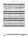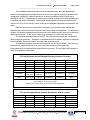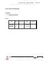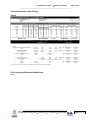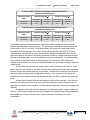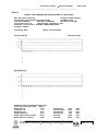
1
Test Report Curtis-Straus LLC, a wholly owned subsidiary of BV CPS Report No Client Address Phone Items tested EO0785-1 CSP Inc. Andrew Shieh 43 Manning Road Billerica, MA 01821 (978) 663-7598 10G-PCIE2-8C2-2T NIC Card in a Host PC Standards EN 55022:2010/AC:2011, ICES-003 Issue 5, CFR 47 FCC Part 15 Subpart B, EN 61000-3-2:2006/A1:2009/A2:2009, EN 61000-3-3:2008, EN 55024:2010 Test Dates April 4, 28 and 29, 2014 Results As detailed within this report Prepared by Ami Soni – Test Engineer Authorized by Stacey Costa – EMC Project Manager Issue Date Conditions of Issue This Test Report is issued subject to the conditions stated in the ‘Conditions of Testing’ section on page 78 of this report. Curtis-Straus LLC is accredited by the American Association for Laboratory Accreditation for the specific scope of accreditation under Certificate Number 1627-01. This report may contain data which is not covered by the A2LA accreditation. ____________________________________________________________ LLC Curtis-Straus LLC, a wholly owned subsidiary of BV CPS One Distribution Center Circle, #1 Littleton, MA TEL (978) 486-8880 FAX (978) 486-8828 page 1 of 79 Test Report for CSP Inc. Report No. EO0785-1 May 16, 2014 ______________________________________________________________________ Contents Contents .................................................................................................................................. 2 Summary ................................................................................................................................. 3 Product Tested ........................................................................................................................ 4 Configuration Documentation ............................................................................................... 4 Clock Frequencies ............................................................................................................... 4 Performance Criteria ............................................................................................................... 5 Compliance Statement ............................................................................................................ 6 Modifications Required for Compliance ................................................................................... 7 RADIATED EMISSIONS.......................................................................................................... 8 CONDUCTED EMISSIONS ................................................................................................... 19 TELCO CONDUCTED EMISSIONS ...................................................................................... 26 ELECTROSTATIC DISCHARGE IMMUNITY ........................................................................ 32 RADIATED RADIO-FREQUENCY IMMUNITY ...................................................................... 39 ELECTRICAL FAST TRANSIENTS IMMUNITY .................................................................... 44 SURGE IMMUNITY ............................................................................................................... 49 CONDUCTED RADIO FREQUENCY IMMUNITY .................................................................. 50 MAGNETIC FIELD IMMUNITY .............................................................................................. 55 VOLTAGE DIPS AND INTERRUPTS IMMUNITY .................................................................. 59 HARMONIC EMISSIONS AND VOLTAGE FLUCTUATIONS/FLICKER ................................ 60 Measurement Uncertainty...................................................................................................... 69 Jurisdictional Labeling and Required Instruction Manual Inserts ............................................ 70 CE Marking - European Union (EU) ................................................................................... 70 Sample Declaration of Conformity ...................................................................................... 70 EN 55022 Class A Warning Requirements......................................................................... 71 FCC Requirements ............................................................................................................ 71 FCC Part 18 Required Labeling for Industrial, Scientific and Medical Equipment ............... 73 Australian Communications and Media Authority (ACMA) .................................................. 74 Canadian Requirements .................................................................................................... 76 VCCI Requirements ........................................................................................................... 76 Conditions Of Testing ............................................................................................................ 78 REV 20-JAN-14 ____________________________________________________________ Curtis-Straus LLC, a wholly owned subsidiary of BV CPS One Distribution Center Circle, #1 Littleton, MA TEL (978) 486-8880 FAX (978) 486-8828 page 2 of 79 Test Report for CSP Inc. Report No. EO0785-1 May 16, 2014 ______________________________________________________________________ Summary On April 4, 28 and 29, 2014 we tested the 10G-PCIE2-8C2-2T NIC Card in a Host PC for compliance with the following requirements: EMC Emissions: EN 55022:2010/AC:2011 Class A ITE emissions requirements (EU) ICES-003 Issue 5 Class A Digital Apparatus emissions requirements (Canada) CFR 47 FCC Part 15 Subpart B Class A emissions requirements (USA) EN 61000-3-2:2006/A1:2009/A2:2009 Limits for harmonic current emissions (equipment input current up to and including 16A per phase) EN 61000-3-3:2008 Limitation of voltage fluctuations and flicker in low-voltage supply systems for equipment with rated current up to and including 16 A EMC Immunity: EN 55024:2010 ITE - immunity characteristics We found that the product met the above requirements without modification. Andrew Shieh from CSP Inc. was present during the testing. The test sample was received in good condition. The sample was received on April 4, 2014. Please note that Radiated and AC Conducted Emissions were tested under Curtis-Straus work order O0761. Issue No. 1 Reason for change Date Issued Original Release May 16, 2014 _____________________________________________________________ Curtis-Straus LLC, a wholly owned subsidiary of BV CPS One Distribution Center Circle, #1 Littleton, MA TEL (978) 486-8880 FAX (978) 486-8828 page 3 of 79 Test Report for CSP Inc. Report No. EO0785-1 May 16, 2014 ______________________________________________________________________ Product Tested Configuration Documentation EUT Configuration Work Order: O0785 Company: CSP Inc. Company Address: 43 Manning Road Billerica MA 01821 Contact: Andrew Shieh Person Present: Andrew Shieh EUT: MN SN 10G-PCIE2-8C2-2T 460249 EUT Description: NIC Card in a Host PC EUT Max Frequency: 800MHz EUT Min Frequency: 0.4MHz Support Equipment: MN SN Dell server Monitor Mouse Keyboard Speakers Microphone PowerEdge T20 Dell Dell Dell Insignia Dynex N/A N/A N/A N/A N/A N/A EUT Ports: Port Label Port Type Ethernet /10G Ethernet Host PC Port Label AC power Mouse connector Keyboard connector Display ports USB VGA Line Out Line In/Microphone Ethernet Serial connector USB (Front) Headphone Input (Front) Microphone Input (Front) Port Type Power PS/2 PS/2 Display USB Video Audio Audio Ethernet Serial USB Audio Audio No. of ports No. Populated 2 No. of ports 1 1 1 2 6 1 1 1 1 1 4 1 No.1 of 2 No. Populated 1 0 0 0 2 1 0 0 0 0 2 1 1 No. Cable Type Shielded Cat6A No Cable Type Shielded 3-wire AC No N/A N/A N/A N/A N/A N/A USB Yes VGA Yes N/A N/A N/A N/A N/A N/A N/A N/A USB Yes Audio No Audio No Cable Type Shielded Ferrites Length No 100ft Ferrites No N/A N/A N/A Yes on 1 cable No N/A N/A N/A N/A No No No Ferrites Length 2.5m N/A N/A N/A 1.5m 1.5m N/A N/A N/A N/A 1.5m 1m 1m Length Max Length In/Out NEBS Type 100m Max Length 2.5m N/A N/A N/A 5m 5m N/A N/A N/A N/A 5m N/A N/A In In/Out NEBS Type In N/A N/A N/A In In N/A N/A N/A N/A In In In Unpopulated Reason Unpopulated Reason Not used in this configuration Not used in this configuration Not used in this configuration Not Not Not Not Not used in this used in this used in this used in this used in this configuration configuration configuration configuration configuration Software / Operating Mode Description: EUT is a Network Interface Card. Clock Frequencies EUT Frequencies (MHz) 0.4 0.5 1 50 100 156.25 364.6 500 800 _____________________________________________________________ Curtis-Straus LLC, a wholly owned subsidiary of BV CPS One Distribution Center Circle, #1 Littleton, MA TEL (978) 486-8880 FAX (978) 486-8828 page 4 of 79 Test Report for CSP Inc. Report No. EO0785-1 May 16, 2014 ______________________________________________________________________ Performance Criteria Criterion A: The unit must operate as intended during the test. In particular, the system shall send and receive packages from the NIC card. Errors are allowed during the ping session, however, the EUT shall not stop sending packages. The monitor shall display a scrolling report of packet counts and errors for both ports. The error count shall increment infrequently. Criterion B: The unit must operate as intended at the conclusion of the test with no loss of state or data. Criterion C: Temporary loss of function is allowed, provided the function is self-recoverable or can be restored by the operation of the controls by the user in accordance with the manufacturer's instructions. _____________________________________________________________ Curtis-Straus LLC, a wholly owned subsidiary of BV CPS One Distribution Center Circle, #1 Littleton, MA TEL (978) 486-8880 FAX (978) 486-8828 page 5 of 79 Test Report for CSP Inc. Report No. EO0785-1 May 16, 2014 ______________________________________________________________________ Compliance Statement TEST RESULT STANDARD TEST LEVEL PASS EN55022:2010/AC:2011 ICES-003 Issue 5 CFR 47 FCC Part 15 Subpart B Class A AC Mains Conducted Emissions PASS EN55022:2010/AC:2011 ICES-003 Issue 5 CFR 47 FCC Part 15 Subpart B Class A Telco Line Conducted Emissions PASS EN55022:2010/AC:2011 Class A ESD PASS EN 61000-4-2 Radiated Emissions ±4kV contact ±8kV air MARGIN -8.3dB @ 2968.0MHz -9.0dB @ 1.020MHz -16.0dB @ 7.623MHz N/A 80-1000MHz RFI Amplitude Modulated PASS EFT PASS EN 61000-4-4 AC Surge N/A EN 61000-4-5 N/A N/A DC Surge N/A EN 61000-4-5 N/A N/A N/A EN 61000-4-5 N/A N/A EN 61000-4-3 @ 3V/m N/A 1KHz 80% AM ±1kV AC main ±0.5kV cables N/A Signal/Telco Surge 0.15-80MHz CRFI PASS EN 61000-4-6 @ 3Vrms COMMENTS N/A 1KHz 80% AM Performance Criteria B Performance Criteria A Performance Criteria B EUT is a card in a host PC No outdoor connections No outdoor connections Performance Criteria A _____________________________________________________________ Curtis-Straus LLC, a wholly owned subsidiary of BV CPS One Distribution Center Circle, #1 Littleton, MA TEL (978) 486-8880 FAX (978) 486-8828 page 6 of 79 Test Report for CSP Inc. Report No. EO0785-1 May 16, 2014 ______________________________________________________________________ TEST RESULT STANDARD TEST LEVEL MARGIN PowerFrequency Magnetic Field PASS EN 61000-4-8 1A/m N/A Voltage Dips And Short Interruptions N/A EN 61000-4-11 N/A N/A Harmonics PASS EN 61000-3-2 Class A N/A Flicker PASS EN 61000-3-3 N/A N/A COMMENTS Performance Criteria A EUT is a card in a host PC Modifications Required for Compliance There were no modifications required for compliance. _____________________________________________________________ Curtis-Straus LLC, a wholly owned subsidiary of BV CPS One Distribution Center Circle, #1 Littleton, MA TEL (978) 486-8880 FAX (978) 486-8828 page 7 of 79 Test Report for CSP Inc. Report No. EO0785-1 May 16, 2014 ______________________________________________________________________ RADIATED EMISSIONS Test Method: In accordance with the following: EN55022:2010/AC:2011 ICES-003 Issue 5 CFR 47 FCC Part 15 Subpart B Results: TEST RESULT TEST LEVEL Radiated Emissions PASS Class A M ARGIN COMMENTS -8.3dB @ 2968.0MHz _____________________________________________________________ Curtis-Straus LLC, a wholly owned subsidiary of BV CPS One Distribution Center Circle, #1 Littleton, MA TEL (978) 486-8880 FAX (978) 486-8828 page 8 of 79 Test Report for CSP Inc. Report No. EO0785-1 May 16, 2014 ______________________________________________________________________ Radiated Emissions Data Table(s): Table 1 Radiated Emissions Table Version 1.017.094 Date: 04-Apr-14 Company: CSP Inc. Engineer: Doug Cormier EUT Desc: NIC Card Temp: 23.7°C Work Order: O0761 EUT Operating Voltage/Frequency: 110Vac/60Hz Humidity: 2% Pressure: 1002mBar Frequency Range: 30-1000MHz Measurement Distance: 3 m Notes: EUT Max Freq: 800MHz CISPR Class A Antenna Pream p Antenna Cable FCC Class A Adjusted Polarization Frequency Reading Factor Factor Factor Reading Lim it Margin Result Lim it Margin Result (H / V) (MHz) (dBµV) (dB) (dB/m) (dB) (dBµV/m) (dBµV/m) (dB) (Pass/Fail) (dBµV/m) (dB) (Pass/Fail) v v v v v v h h h h 48.25 51.5 55.4 61.7 468.7 624.9 55.9 143.9 468.7 624.98 46.3 46.7 49.6 43.8 43.0 40.5 48.9 42.4 40.8 41.0 22.5 22.5 22.5 22.5 22.3 22.6 22.5 22.5 22.3 22.6 8.6 7.5 6.9 7.4 17.3 19.3 6.9 12.5 17.3 19.3 0.5 0.5 0.6 0.6 1.6 1.8 0.6 0.8 1.6 1.8 32.9 32.2 34.6 29.3 39.6 39.0 33.9 33.2 37.4 39.5 50.5 50.5 50.5 50.5 57.5 57.5 50.5 50.5 57.5 57.5 -17.6 -18.3 -15.9 -21.2 -17.9 -18.5 -16.6 -17.3 -20.1 -18.0 Pass Pass Pass Pass Pass Pass Pass Pass Pass Pass 49.5 49.5 49.5 49.5 56.9 56.9 49.5 54.0 56.9 56.9 -16.6 -17.3 -14.9 -20.2 -17.3 -17.9 -15.6 -20.8 -19.5 -17.4 Pass Pass Pass Pass Pass Pass Pass Pass Pass Pass Pass by Table Result: Test Site: EMI Chamber 2 Analyzer: Asset #1328 -14.9 dB Worst Freq: Cable 1: Asset #1506 Preamp: Blue Cable 2: Asset #1786 Antenna: Red-Black Rev. 4/2/2014 Spectrum Analyzers / Receivers /Preselectors Range MN Mfr SN SA EMI Chamber (1328) 9kHz-13.2 GHz E4405B Agilent MY44210241 _ Radiated Emissions Sites FCC Code IC Code VCCI Code Range EMI Chamber 2 719150 2762A-7 A-0015 30-1000MHz _ Preamps /Couplers Attenuators / Filters Range MN Mfr SN Blue 0.009-2000MHz ZFL-1000-LN CS N/A _ Antennas Range MN Mfr SN Red-Black Bilog 30-2000MHz JB1 Sunol A091604-2 _ Meteorological Meters MN Mfr SN Temp./Humidity/Atm. Pressure Gauge 7400 Perception II Davis N/A TH A#1833 35519-044 Control Company 130318278 _ Cables Range Mfr Asset #1506 9kHz - 18GHz Florida RF Asset #1786 9kHz - 18GHz Florida RF _ All equipment is calibrated using standards traceable to NIST or other nationally recognized calibration standard. Asset 1328 55.4 MHz Cable 3: --Preselector: --- Cat I Calibration Due 1/13/2015 Calibrated on 1/13/2014 Cat II Calibration Due 3/9/2015 Calibrated on 3/9/2014 Asset 759 Cat II Calibration Due 5/31/2014 Calibrated on 5/31/2013 Asset 1106 Cat I Calibration Due 1/28/2015 Calibrated on 1/28/2013 Asset 965 1833 Cat I II Calibration Due 5/29/2014 6/13/2015 Calibrated on 5/29/2013 6/13/2013 Cat II II Calibration Due 3/7/2015 3/15/2015 Calibrated on 3/7/2014 3/15/2014 Table 2 Radiated Emissions Table Version 1.017.094 Date: 04-Apr-14 Company: CSP Inc. Engineer: Doug Cormier EUT Desc: NIC Card Temp: 23.7°C Work Order: O0761 EUT Operating Voltage/Frequency: 110Vac/60Hz Humidity: 2% Pressure: 1002mBar Frequency Range: 1-6GHz Measurement Distance: 3 m Notes: EUT Max Freq: 800MHz Antenna Polarization Peak Average Pream p Antenna Cable Adjusted Adjusted CISPR Class A High Frequency Peak CISPR Class A High Frequency Average Frequency Reading Reading Factor Factor Factor Peak Reading Avg Reading Lim it Margin Result Lim it Margin Result (H / V) (MHz) (dBµV) (dBµV) (dB) (dB/m) (dB) (dBµV/m) (dBµV/m) (dBµV/m) (dB) (Pass/Fail) (dBµV/m) (dB) (Pass/Fail) v v v v v v h h 1284.0 1458.0 1562.0 1715.0 1995.0 2344.0 1713.0 2968.0 67.5 61.0 57.7 60.6 56.7 54.8 64.3 60.9 45.0 48.0 49.4 41.8 39.1 46.0 42.2 55.6 44.8 43.6 43.4 42.8 41.5 41.3 42.8 42.2 25.1 25.3 25.5 26.1 27.7 28.0 26.1 29.9 2.5 3.1 3.0 3.1 3.5 3.9 3.1 4.4 50.3 45.8 42.8 47.0 46.4 45.4 50.7 53.0 27.8 32.8 34.5 28.2 28.8 36.6 28.6 47.7 76.0 76.0 76.0 76.0 76.0 76.0 76.0 76.0 -25.7 -30.2 -33.2 -29.0 -29.6 -30.6 -25.3 -23.0 Pass Pass Pass Pass Pass Pass Pass Pass 56.0 56.0 56.0 56.0 56.0 56.0 56.0 56.0 -28.2 -23.2 -21.5 -27.8 -27.2 -19.4 -27.4 -8.3 Pass Pass Pass Pass Pass Pass Pass Pass Table Result: Test Site: EMI Chamber 2 Analyzer: Asset #1328 Pass by -8.3 dB Cable 1: Asset #1506 Preamp: Red-Blue Worst Freq: Cable 2: Asset #1786 Antenna: Yellow Horn 2968.0 MHz Cable 3: --Preselector: --- _____________________________________________________________ Curtis-Straus LLC, a wholly owned subsidiary of BV CPS One Distribution Center Circle, #1 Littleton, MA TEL (978) 486-8880 FAX (978) 486-8828 page 9 of 79 Test Report for CSP Inc. Report No. EO0785-1 May 16, 2014 ______________________________________________________________________ Table 3 Radiated Emissions Table Version 1.017.094 Date: 04-Apr-14 Company: CSP Inc. Engineer: Doug Cormier EUT Desc: NIC Card Temp: 23.7°C Work Order: O0761 EUT Operating Voltage/Frequency: 110Vac/60Hz Humidity: 2% Pressure: 1002mBar Frequency Range: 1-6GHz Measurement Distance: 3 m Notes: EUT Max Freq: 800MHz Antenna Peak Average Pream p Antenna Cable Adjusted Adjusted FCC Class A High Frequency Peak FCC Class A High Frequency Average Polarization Frequency Reading Reading Factor Factor Factor Peak Reading Avg Reading Lim it Margin Result Lim it Margin Result (H / V) (MHz) (dBµV) (dBµV) (dB) (dB/m) (dB) (dBµV/m) (dBµV/m) (dBµV/m) (dB) (Pass/Fail) (dBµV/m) (dB) (Pass/Fail) v v v v v v h h 1284.0 1458.0 1562.0 1715.0 1995.0 2344.0 1713.0 2968.0 67.5 61.0 57.7 60.6 56.7 54.8 64.3 60.9 45.0 48.0 49.4 41.8 39.1 46.0 42.2 55.6 44.8 43.6 43.4 42.8 41.5 41.3 42.8 42.2 25.1 25.3 25.5 26.1 27.7 28.0 26.1 29.9 2.5 3.1 3.0 3.1 3.5 3.9 3.1 4.4 50.3 45.8 42.8 47.0 46.4 45.4 50.7 53.0 27.8 32.8 34.5 28.2 28.8 36.6 28.6 47.7 80.0 80.0 80.0 80.0 80.0 80.0 80.0 80.0 -29.7 -34.2 -37.2 -33.0 -33.6 -34.6 -29.3 -27.0 Pass Pass Pass Pass Pass Pass Pass Pass 60.0 60.0 60.0 60.0 60.0 60.0 60.0 60.0 -32.2 -27.2 -25.5 -31.8 -31.2 -23.4 -31.4 -12.3 Pass Pass Pass Pass Pass Pass Pass Pass Table Result: Pass Test Site: EMI Chamber 2 Analyzer: Asset #1328 -12.3 dB by Worst Freq: Cable 1: Asset #1506 Preamp: Red-Blue Cable 2: Asset #1786 Antenna: Yellow Horn 2968.0 MHz Cable 3: --Preselector: --- Table 4 Radiated Emissions Table Version 1.017.094 Date: 04-Apr-14 Company: CSP Inc. Engineer: Doug Cormier EUT Desc: NIC Card Temp: 23.7°C Work Order: O0761 EUT Operating Voltage/Frequency: 110Vac/60Hz Humidity: 2% Pressure: 1002mBar Frequency Range: 6-10GHz Measurement Distance: 1 m Notes: EUT Max Freq: 800MHz Antenna Peak Average Pream p Antenna Cable Adjusted Adjusted FCC Class A High Frequency Peak FCC Class A High Frequency Average Polarization Frequency Reading Reading Factor Factor Factor Peak Reading Avg Reading Lim it Margin Result Lim it Margin Result (H / V) (MHz) (dBµV) (dBµV) (dB) (dB/m) (dB) (dBµV/m) (dBµV/m) (dBµV/m) (dB) (Pass/Fail) (dBµV/m) (dB) (Pass/Fail) No Emissions found Table Result: --- Test Site: EMI Chamber 2 Analyzer: Asset #1328 --- dB by Worst Freq: Cable 1: Asset #1506 Preamp: Red-Blue Cable 2: Asset #1786 Antenna: Yellow Horn --- MHz Cable 3: --Preselector: --- Table 5 Radiated Emissions Table Version 1.017.094 Date: 04-Apr-14 Company: CSP Inc. Engineer: Doug Cormier EUT Desc: NIC Card Temp: 23.7°C Work Order: O0761 EUT Operating Voltage/Frequency: 110Vac/60Hz Humidity: 2% Pressure: 1002mBar Frequency Range: 10-12.5GHz Measurement Distance: 1 m Notes: EUT Max Freq: 800MHz Antenna Peak Average Pream p Antenna Cable Adjusted Adjusted FCC Class A High Frequency Peak FCC Class A High Frequency Average Polarization Frequency Reading Reading Factor Factor Factor Peak Reading Avg Reading Lim it Margin Result Lim it Margin Result (H / V) (MHz) (dBµV) (dBµV) (dB) (dB/m) (dB) (dBµV/m) (dBµV/m) (dBµV/m) (dB) (Pass/Fail) (dBµV/m) (dB) (Pass/Fail) No Emissions found Table Result: Test Site: EMI Chamber 2 Analyzer: Asset #1328 --- by --- dB Cable 1: --Preamp: Red-Blue Worst Freq: Cable 2: Asset #1786 Antenna: Yellow Horn --- MHz Cable 3: --Preselector: --- _____________________________________________________________ Curtis-Straus LLC, a wholly owned subsidiary of BV CPS One Distribution Center Circle, #1 Littleton, MA TEL (978) 486-8880 FAX (978) 486-8828 page 10 of 79 Test Report for CSP Inc. Report No. EO0785-1 May 16, 2014 ______________________________________________________________________ Rev. 4/2/2014 Spectrum Analyzers / Receivers /Preselectors Range MN Mfr SN SA EMI Chamber (1328) 9kHz-13.2 GHz E4405B Agilent MY44210241 _ Radiated Emissions Sites FCC Code IC Code VCCI Code Range EMI Chamber 2 719150 2762A-7 A-0015 >1GHz _ Preamps /Couplers Attenuators / Filters Range MN Mfr SN Red-Blue 1-18GHz PE2-38-218-4R5-17-15-SFF CS NA _ Antennas Range MN Mfr SN Yellow Horn 1-18GHz 3115 EMCO 9608-4898 _ Meteorological Meters MN Mfr SN Temp./Humidity/Atm. Pressure Gauge 7400 Perception II Davis N/A TH A#1833 35519-044 Control Company 130318278 _ Cables Range Mfr Asset #1506 9kHz - 18GHz Florida RF Asset #1786 9kHz - 18GHz Florida RF _ All equipment is calibrated using standards traceable to NIST or other nationally recognized calibration standard. Asset 1328 Cat I Calibration Due 1/13/2015 Calibrated on 1/13/2014 Cat I Calibration Due 5/16/2015 Calibrated on 5/16/2013 Asset 1257 Cat II Calibration Due 9/13/2014 Calibrated on 9/13/2013 Asset 37 Cat I Calibration Due 7/19/2014 Calibrated on 7/19/2013 Asset 965 1833 Cat I II Calibration Due 5/29/2014 6/13/2015 Calibrated on 5/29/2013 6/13/2013 Cat II II Calibration Due 3/7/2015 3/15/2015 Calibrated on 3/7/2014 3/15/2014 Radiated Emissions Modifications: None _____________________________________________________________ Curtis-Straus LLC, a wholly owned subsidiary of BV CPS One Distribution Center Circle, #1 Littleton, MA TEL (978) 486-8880 FAX (978) 486-8828 page 11 of 79 Test Report for CSP Inc. Report No. EO0785-1 May 16, 2014 ______________________________________________________________________ Radiated Emissions Setup Photograph(s): 30-1000MHz (Front) 30-1000MHz (Rear) _____________________________________________________________ Curtis-Straus LLC, a wholly owned subsidiary of BV CPS One Distribution Center Circle, #1 Littleton, MA TEL (978) 486-8880 FAX (978) 486-8828 page 12 of 79 Test Report for CSP Inc. Report No. EO0785-1 May 16, 2014 ______________________________________________________________________ 1-6GHz (Front) 1-6GHz (Rear) _____________________________________________________________ Curtis-Straus LLC, a wholly owned subsidiary of BV CPS One Distribution Center Circle, #1 Littleton, MA TEL (978) 486-8880 FAX (978) 486-8828 page 13 of 79 Test Report for CSP Inc. Report No. EO0785-1 May 16, 2014 ______________________________________________________________________ 6-12.5GHz (Front) 6-12.5GHz (Rear) _____________________________________________________________ Curtis-Straus LLC, a wholly owned subsidiary of BV CPS One Distribution Center Circle, #1 Littleton, MA TEL (978) 486-8880 FAX (978) 486-8828 page 14 of 79 Test Report for CSP Inc. Report No. EO0785-1 May 16, 2014 ______________________________________________________________________ Radiated Emissions Testing Overview REV 10-APR-09 Digital and microprocessor based devices use radio frequency (RF) digital signals for timing purposes. An unintentional consequence of this signal usage is that a certain amount of RF energy is radiated from the device into the local environment. This radiated RF energy has the potential to interfere with constructive uses of the RF spectrum such as television broadcasting, police and fire radio, and the like. In order to reduce the likelihood that a device will interfere with these services, it is required that the amplitudes of radiated RF signals from the device are kept below an allowable level. These RF signals decrease in strength as the distance from the source increases. Thus if the potential victim of interference, e.g. a TV receiver, is far enough from the radiator, e.g. a computer, then no interference will occur. For certain environments it is appropriate to expect that potential interference victims will be located at least a minimum distance from the radiator. For the residential environment this distance is generally accepted to be 10 meters while in the commercial environment the accepted distance is 30 meters. The allowable emissions levels are therefore specified to protect equipment which is located further than that distance from the radiator. In general, radiation from the Equipment Under Test (EUT) is measured at 3 or 10 meters to insure that it is at or below allowable levels. Measurements of the radiated energy are made by recording the field strength indicated by an antenna placed at a specific distance from the device. Most devices do not radiate the RF energy in a predictable manner. The emitted energy may vary with changes in operating mode, physical configuration, or orientation. During the measurement process these parameters are varied to confirm that the emissions will remain below the allowable levels in the range of typical installations. The extent of annoyance experienced by a person who is being affected by interference is related to the persistence of the interfering signal. For example, a low level steady whine from a receiver is considered to be more annoying than brief, loud, intermittent pops or clicks. This “human factor” is accounted for by the use of a “quasi-peak” detector in the receiver or spectrum analyzer which measures the signal from the measurement antenna. The detector is a weighted averaging filter with a fast charge time and a slow discharge time. Thus steady continuous signals will charge the quasi-peak detector fully while intermittent signals (those with pulse repetition rates less than 1kHz) are reported at a level which can be significantly below their peak level. It should be noted that most RF signals produced by digital devices are continuous in nature and thus the quasi-peak reading will be identical to the peak signal reading. To reduce the test time, the peak emission level is recorded for continuous wave signals as it is the same as the quasi-peak signal level. Testing is performed according to test methods from ANSI C63.4 and CISPR 22. The test site used for measuring radiated emissions follows the format developed internationally for a weather protected Open Area Test Site (OATS). The test site used for measuring radiated emissions above 1GHz for CISPR limits is a Free Space Open Area Test Site (FSOATS). An antenna mast is installed at the specified distance from a rotating table and is used to raise and lower the measuring antenna. The reference site is clear of reflecting objects, such as metal fences and buildings for an ellipse of twice the measurement test _____________________________________________________________ Curtis-Straus LLC, a wholly owned subsidiary of BV CPS One Distribution Center Circle, #1 Littleton, MA TEL (978) 486-8880 FAX (978) 486-8828 page 15 of 79 Test Report for CSP Inc. Report No. EO0785-1 May 16, 2014 ______________________________________________________________________ distance. Measuring equipment and personnel are present within the ellipse to facilitate cable manipulation, but measures are taken to minimize the effects. Often preliminary radiated emissions measurements are made at alternate test sites which do not meet the clear space reference criteria. The data collected at alternate test sites is not considered conclusive unless the alternate site also complies with a volumetric site attenuation survey performed over the area that the EUT occupies. The EUT and measuring antenna mark the two foci of the ellipse. The ground plane is made of a combination of galvanized steel sheets and tight wire mesh electrically connected along the seams. This metal ground plane extends 1 meter beyond the furthest extent of the EUT and the measuring antenna. It also covers the area between the EUT and the measuring antenna. The hardware cloth is connected to the utility ground or to stakes driven into the earth for safety. The site configuration for CISPR testing above 1GHz is a semianechoic chamber. The ground plane in the test volume is covered by an absorbing material between the antenna and the EUT. In the case of table top equipment, the absorbing material is also placed under the table. In the case of floor-standing equipment the absorbing material extends up from the ground plane 30cm into the test volume, and surrounds the EUT by at most 10cm from the footprint of the equipment. In order for accurate emissions measurements to be made the test site must possess propagation characteristics which fall within accepted norms. The site has been checked for suitability using techniques specified in American National Standards Institute (ANSI) document C63.4. This document details a procedure which measures the attenuation of the site which is the chief indicator of site acceptability. The theory behind site attenuation is quite simple. A transmitting antenna is set up at a fixed location at one end of the site with a receiving antenna at the other end. If a signal of some arbitrary amplitude is fed into the transmitting antenna, a lesser amount of signal ought to be measured at the receiving antenna. This difference in signal amplitude is known as the site attenuation, which should follow a predicted curve. Data that does not correspond to the predicted site attenuation curve points to a problem with either the equipment being used or the physical characteristics of the site. Actual emissions measurements are taken with broadband biconical-log-periodic hybrid antennas calibrated in accordance with the standard site method detailed in ANSI C63.5. Emissions are measured with the receiving antenna oriented in horizontal and vertical polarization with respect to the ground plane. If measurements are made at other than the limit distance, then the readings obtained are scaled to the limit distance using an inverse relationship. The actual test distance used is noted in the report. The antenna mast is capable of a varying the antenna height between 1 and 4 meters above the ground plane. The receiving antenna is moved over this range at each emission frequency in order to record the maximum observed signal. The mast is non-conductive and remotely controllable. The test distance is measured from the antenna center (marked during calibration) and the periphery of the EUT. The Equipment Under Test (EUT) is rotated in order to maximize emissions during the test. For equipment intended to operate on a tabletop or desk radiated tests are conducted on a 0.8 meter high, non-conductive platform. Larger floor standing equipment is tested on a floor mounted rotatable platform. In some cases, large equipment on its own casters may be tested without a platform. _____________________________________________________________ Curtis-Straus LLC, a wholly owned subsidiary of BV CPS One Distribution Center Circle, #1 Littleton, MA TEL (978) 486-8880 FAX (978) 486-8828 page 16 of 79 Test Report for CSP Inc. Report No. EO0785-1 May 16, 2014 ______________________________________________________________________ Since radiated emissions are a function of cable placement, the cable placement is varied to encompass typical configurations that an end user might encounter to determine the configuration resulting in maximum emissions. At least one cable for each I/O port type is attached to the EUT. If peripherals or modules are available, at least one of each available type is installed and noted in the report. Excess cable length beyond one meter is bundled in the center into a 30 to 40 cm bundle. Cables requiring non-standard lead dress are recorded in the report. Network connections are simulated if necessary. Any simulator used matches the expected real network connection in terms of both functionality and impedance. For distributed systems, the support equipment may be placed at such a distance that it does not influence the measured emissions. If this option is used, such placement is noted in the test report. The possible operating modes of the EUT are explored to determine the configuration which maximizes emissions. Software is investigated as well as different methods of displaying data if available. Data is recorded in the worst case operating mode. At least the six highest emissions with respect to the limit are recorded. If less than six emissions are visible above the noise floor of the instrumentation, then noise floor measurements at six representative frequencies are recorded. The test report will document if noise floor readings are reported. FCC and European Norms Radiated Emissions Limits at 10 meters Frequency (MHz) 30-88 88-216 216-230 230-960 960-1000 1000-3000 3000+ FCC Class A 39.1 43.5 46.4 46.4 49.5 Avg: 49.5 Peak: 69.5 Avg: 49.5 Peak: 69.5 FCC Class B 29.5 33.1 35.6 35.6 43.5 Avg: 43.5 Peak: 63.5 Avg: 43.5 Peak: 63.5 CISPR Class A 40 40 40 47 47 CISPR Class B 30 30 30 37 37 Frequency (MHz) 30-88 88-216 216-230 230-960 960-1000 Not defined Not defined 1000-3000 Not defined Not defined 3000+ At the transitions, the lower limit applies. Simple inverse scaling utilized to convert limits where appropriate. FCC and European Norms Radiated Emissions Limits at 3 meters Frequency (MHz) 30-88 88-216 216-230 230-960 960-1000 FCC Class A 49.5 54 56.9 56.9 60 FCC Class B 40 43.5 46 46 54 CISPR Class A 50.5 50.5 50.5 57.5 57.5 CISPR Class B 40.5 40.5 40.5 47.5 47.5 Frequency (MHz) 30-88 88-216 216-230 230-960 960-1000 _____________________________________________________________ Curtis-Straus LLC, a wholly owned subsidiary of BV CPS One Distribution Center Circle, #1 Littleton, MA TEL (978) 486-8880 FAX (978) 486-8828 page 17 of 79 Test Report for CSP Inc. Report No. EO0785-1 May 16, 2014 ______________________________________________________________________ 1000-3000 3000+ Avg: 60 Peak: 80 Avg: 60 Peak: 80 Avg: 54 Peak: 74 Avg: 54 Peak: 74 Avg: 56 Peak: 76 Avg: 60 Peak: 80 Avg: 50 Peak: 70 Avg: 54 Peak: 74 1000-3000 3000+ At the transitions, the lower limit applies. Simple inverse scaling utilized to convert limits where appropriate. The measurement range is based on the highest frequency signal present or used in the device. The following table details the frequency range of measurements performed. Frequency range of radiated emissions measurements Highest frequency generated or used in the device or on which the device operates or tunes (MHz) Below 1.705 1.705-108 108-500 500-1000 Above 1000 Upper frequency of measurement range (MHz) FCC EU/CISPR 30 (No radiated measurements) 1000 2000 5000 5th harmonic of the highest frequency 40 GHz whichever is lower. 1000 1000 2000 5000 5th harmonic of the highest frequency 6 GHz whichever is lower. The test data is derived from the voltage on the spectrum analyzer. First the reading is corrected for gain factors associated with the use of preamps and loss in the cable. A factor in dB is subtracted from the reading to account for preamp gain, while a factor in dB is added to the signal to account for cable loss. A conversion is performed from the resulting voltage to field strength by multiplying the voltage by the antenna factor. Since antenna factor is expressed as a logarithm (dB/m), this operation takes the form of an addition (to multiply logarithmic numbers, you add them together). Thus: Field Strength (dBuV/m) = Voltage Reading (dBuV) - Preamp Gain (dB) + Cable Loss (dB) + Antenna Factor (dB/m) When the levels of ambient radio signals such as local television stations are within 6 dB of the appropriate limit, the following steps may be taken to assure compliance: 1. The measurement bandwidth may be reduced. A check is made to see that peak readings are not affected. The use of a narrower bandwidth allows examination of emissions close to local ambient signals. 2. The antenna may be brought closer to the EUT to increase signal-to-ambient signal strength. 3. For horizontally polarized signals the axis of the test site may be rotated to discriminate against local ambients. _____________________________________________________________ Curtis-Straus LLC, a wholly owned subsidiary of BV CPS One Distribution Center Circle, #1 Littleton, MA TEL (978) 486-8880 FAX (978) 486-8828 page 18 of 79 Test Report for CSP Inc. Report No. EO0785-1 May 16, 2014 ______________________________________________________________________ CONDUCTED EMISSIONS Test Method: In accordance with the following: EN55022:2010/AC:2011 ICES-003 Issue 5 CFR 47 FCC Part 15 Subpart B Results: TEST RESULT TEST LEVEL AC Mains Conducted Emissions PASS Class A MARGIN COMMENTS -9.0dB @ 1.020MHz _____________________________________________________________ Curtis-Straus LLC, a wholly owned subsidiary of BV CPS One Distribution Center Circle, #1 Littleton, MA TEL (978) 486-8880 FAX (978) 486-8828 page 19 of 79 Test Report for CSP Inc. Report No. EO0785-1 May 16, 2014 ______________________________________________________________________ Conducted Emissions Data Table(s): Table 6 AC Conducted Emissions Data Table Date: 04-Apr-14 Engineer: Doug Cormier Temp: 23.9 ºC Notes: Company: CSP Inc. EUT Desc: NIC Card Humidity: 20% Work Order: O0761 Pressure: 1002 mBar Frequency Range: 0.15-30MHz Quasi-Peak Readings QP1 QP2 (dBµV) (dBµV) 25.5 26.3 14.3 14.8 16.6 17.5 16.7 16.9 16.3 16.5 15.3 15.7 Frequency (MHz) 0.20 0.89 1.78 1.97 2.17 2.36 Average Readings AVG1 AVG2 (dBµV) (dBµV) 22.0 22.0 11.7 11.9 10.8 11.4 9.0 9.2 8.3 8.6 7.7 8.2 LISN Factors L1 (dB) -0.1 0.0 -0.1 -0.1 -0.1 -0.1 Cable Factor (dB) -0.1 -0.1 -0.1 -0.1 -0.1 -0.1 L2 (dB) -0.1 0.0 0.0 0.0 0.0 0.0 Result: Pass ATTN Factor (dB) -19.8 -19.8 -19.8 -19.8 -19.8 -19.8 EUT Input Voltage/Frequency: 220Vac/60Hz FCC/CISPR Class A FCC/CISPR Class A QP Limit Margin Result AVG Limit Margin Result (dBµV) (dB) (Pass/Fail) (dBµV) (dB) (Pass/Fail) 79.0 -32.8 Pass 66.0 -24.1 Pass 73.0 -38.3 Pass 60.0 -28.2 Pass 73.0 -35.6 Pass 60.0 -28.7 Pass 73.0 -36.2 Pass 60.0 -30.9 Pass 73.0 -36.6 Pass 60.0 -31.5 Pass 73.0 -37.4 Pass 60.0 -31.9 Pass Worst Margin: Measurement Device: LISN ASSET 1732(Line 1) LISN ASSET 1733(Line 2) Frequency: -24.1 dB Cable: CEMI-05 Attenuator: 20dB Attenuator-73 0.198 MHz Spectrum Analyzer: SA EMI Chamber (1328) Site: CEMI 3 Rev. 4/2/2014 Spectrum Analyzers / Receivers /Preselectors Range MN Mfr SN SA EMI Chamber (1328) 9kHz-13.2 GHz E4405B Agilent MY44210241 _ LISNs/Measurement Probes Range MN Mfr SN LISN Asset 1732 150kHz-30MHz LI-150A Com-Power 201094 LISN Asset 1733 150kHz-30MHz LI-150A Com-Power 201095 _ Conducted Test Sites (Mains / Telco) FCC Code VCCI Code CEMI 3 719150 A-0015 _ Meteorological Meters MN Mfr SN Temp./Humidity/Atm. Pressure Gauge 7400 Perception II Davis N/A TH A#1828 35519-044 Control Company 130318292 _ Cables Range Mfr CEMI-05 9kHz - 2GHz C-S _ Attenuators Range MN Mfr SN 20dB Attenuator-73 9kHz-2GHz N/A _ All equipment is calibrated using standards traceable to NIST or other nationally recognized calibration standard. Asset 1328 Cat I Calibration Due 1/13/2015 Calibrated on 1/13/2014 Asset 1732 1733 Cat I I Calibration Due 2/10/2015 2/10/2015 Calibrated on 2/10/2014 2/10/2014 Cat III Calibration Due NA Calibrated on N/A Cat I II Calibration Due 5/29/2014 6/13/2015 Calibrated on 5/29/2013 6/13/2013 Cat II Calibration Due 5/3/2014 Calibrated on 5/3/2013 Cat II Calibration Due 10/12/2014 Calibrated on 10/12/2013 Asset 965 1828 Asset Table 7 AC Conducted Emissions Data Table Date: 29-Apr-14 Engineer: Disha Vachhani Temp: 24.3 ºC Notes: Company: CSP Inc. EUT Desc: NIC Card Humidity: 21% Work Order: O0785 Pressure: 1017 mBar Frequency Range: 0.15-30MHz Frequency (MHz) 0.20 0.51 0.89 1.02 1.53 2.54 Quasi-Peak Readings QP1 QP2 (dBµV) (dBµV) 24.9 24.5 22.5 21.4 30.2 29.8 30.7 29.6 29.4 27.9 20.2 18.6 Average Readings AVG1 AVG2 (dBµV) (dBµV) 21.6 21.4 21.5 20.2 30.0 29.6 30.5 29.4 29.2 27.8 18.8 16.8 LISN Factors L1 L2 (dB) (dB) -0.1 -0.1 0.0 0.0 0.0 0.0 0.0 0.0 0.0 0.0 0.0 0.0 Result: Pass Measurement Device: LISN ASSET 1726(Line 1) LISN ASSET 1727(Line 2) Cable Factor (dB) -0.1 -0.1 -0.1 -0.1 -0.1 -0.1 ATTN Factor (dB) -20.4 -20.4 -20.4 -20.4 -20.4 -20.4 EUT Input Voltage/Frequency: 120V, 60Hz FCC/CISPR Class A FCC/CISPR Class A QP Limit Margin Result AVG Limit Margin Result (dBµV) (dB) (Pass/Fail) (dBµV) (dB) (Pass/Fail) 79.0 -33.6 Pass 66.0 -23.9 Pass 73.0 -30.0 Pass 60.0 -18.0 Pass 73.0 -22.3 Pass 60.0 -9.5 Pass 73.0 -21.8 Pass 60.0 -9.0 Pass 73.0 -23.1 Pass 60.0 -10.3 Pass 73.0 -32.3 Pass 60.0 -20.7 Pass Worst Margin: Cable: CEMI-09 Attenuator: 20dB Atten-4 -9.0 dB Frequency: 1.020 MHz Spectrum Analyzer: Yellow Site: CEMI 5 _____________________________________________________________ Curtis-Straus LLC, a wholly owned subsidiary of BV CPS One Distribution Center Circle, #1 Littleton, MA TEL (978) 486-8880 FAX (978) 486-8828 page 20 of 79 Test Report for CSP Inc. Report No. EO0785-1 May 16, 2014 ______________________________________________________________________ Rev. 4/20/2014 Spectrum Analyzers / Receivers /Preselectors Range MN Mfr Yellow 9kHz-2.9GHz 8594E Agilent _ LISNs/Measurement Probes Range MN Mfr LISN Asset 1726 150kHz-30MHz LI-150A Com-Power LISN Asset 1727 150kHz-30MHz LI-150A Com-Power _ Conducted Test Sites (Mains / Telco) FCC Code VCCI Code CEMI 5 719150 A-0015 _ Meteorological Meters MN Mfr Temp./Humidity/Atm. Pressure Gauge 7400 Perception II Davis TH A#1830 35519-044 Control Company _ Cables Range Mfr CEMI-09 9kHz - 2GHz C-S _ Attenuators Range MN Mfr 20dB Atten-4 9kHz-2GHz _ All equipment is calibrated using standards traceable to NIST or other nationally recognized calibration standard. SN 3523A01958 Asset 100 Cat I Calibration Due 6/3/2014 Calibrated on 6/3/2013 SN 201092 201093 Asset 1726 1727 Cat I I Calibration Due 1/15/2015 1/15/2015 Calibrated on 1/15/2014 1/15/2014 Cat III Calibration Due NA Calibrated on N/A Cat I II Calibration Due 5/29/2014 6/13/2015 Calibrated on 5/29/2013 6/13/2013 Cat II Calibration Due 5/9/2014 Calibrated on 5/9/2013 Cat II Calibration Due 7/12/2014 Calibrated on 12/7/2013 SN N/A 130320003 SN N/A Asset 965 1830 Asset Conducted Emissions Modifications: None _____________________________________________________________ Curtis-Straus LLC, a wholly owned subsidiary of BV CPS One Distribution Center Circle, #1 Littleton, MA TEL (978) 486-8880 FAX (978) 486-8828 page 21 of 79 Test Report for CSP Inc. Report No. EO0785-1 May 16, 2014 ______________________________________________________________________ Conducted Emissions Setup Photograph(s): Front _____________________________________________________________ Curtis-Straus LLC, a wholly owned subsidiary of BV CPS One Distribution Center Circle, #1 Littleton, MA TEL (978) 486-8880 FAX (978) 486-8828 page 22 of 79 Test Report for CSP Inc. Report No. EO0785-1 May 16, 2014 ______________________________________________________________________ Rear _____________________________________________________________ Curtis-Straus LLC, a wholly owned subsidiary of BV CPS One Distribution Center Circle, #1 Littleton, MA TEL (978) 486-8880 FAX (978) 486-8828 page 23 of 79 Test Report for CSP Inc. Report No. EO0785-1 May 16, 2014 ______________________________________________________________________ Line Conducted Emissions Overview: REV 9-MAY-06 Digital and microprocessor based devices use radio frequency (RF) digital techniques for timing purposes and in applications such as switching power supplies. An unintentional consequence of this for AC powered devices is that a certain amount of the RF energy is impressed upon the AC power mains in the form of a conducted noise voltage. These conducted emissions have the potential to interfere with constructive uses of the RF spectrum such as AM radio and may also interfere with other devices attached to the same AC mains circuit. In order to reduce the likelihood that a device will interfere it is required that the conducted RF signals from the device are below an allowable level. Testing is performed according to test methods from ANSI C63.4 and CISPR 22. Line conducted emissions are measured from the device over the frequency range of 0.15 to 30 MHz. The EUT is powered from a Line Impedance Stabilization Network (LISN). The purpose of the LISN is to provide a calibrated impedance across which to measure the conducted emissions. The RF noise voltage produced by the EUT across the LISN is measured and compared to the limit. In order for the LISN to perform properly it is attached to a ground plane at least 2 meters by 2 meters in size. For tabletop equipment the measurement is performed with the equipment 40 cm from a vertical conducting surface bonded to a ground plane under the product. The ground plane extends 0.5 meters beyond the product and is 2.5mx3.7m in size. The vertical surface is 2.5mx2.5m. As with radiated emissions, the “human factor” is accounted for by the use of a “quasipeak” detector in the receiver or spectrum analyzer that measures the signal from the LISN. For certain tests (such as EN55022), both an average and a quasi-peak limit are specified. Emissions from a device must be below both limits when measured with the appropriate detector. If the emission level is below the average limit when measured with the quasi-peak detector, the EUT is presumed to pass both limits. The possible operating modes of the EUT are explored to determine the configuration that maximizes emissions. Software is investigated as well as different methods of displaying data if available. Data is recorded in the worst case operating mode. As of September 9, 2002, the FCC has harmonized it’s conducted emission limits with CISPR. The following table displays the limits applicable to both FCC and CISPR. _____________________________________________________________ Curtis-Straus LLC, a wholly owned subsidiary of BV CPS One Distribution Center Circle, #1 Littleton, MA TEL (978) 486-8880 FAX (978) 486-8828 page 24 of 79 Test Report for CSP Inc. Report No. EO0785-1 May 16, 2014 ______________________________________________________________________ Line Conducted Emissions Limits: Class A (dBµV) Frequency (MHz) 0.15 - 0.5 0.5 - 30 Quasi-Peak 79 73 Average 66 60 Line Conducted Emissions Limits: Class B (dBµV) Frequency (MHz) 0.15 - 0.5 0.5 - 5 5 - 30 Quasi-Peak 66 - 56* 56 60 Average 56 - 46* 46 50 Note 1: The lower limit applies at the transition frequencies *Note 2: The limit decreases linearly with the logarithm of the frequency At least the six highest emissions with respect to the limit are recorded. If less than six emissions are visible above the noise floor of the instrumentation, then the noise floor at six representative frequencies is recorded. The test report will document if noise floor readings are reported. All testing is performed within the framework of a laboratory quality system modeled on ISO/IEC 17025 General requirements for the competence of calibration and testing laboratories and is subject to our terms and conditions. This test method is covered by our A2LA accreditation. _____________________________________________________________ Curtis-Straus LLC, a wholly owned subsidiary of BV CPS One Distribution Center Circle, #1 Littleton, MA TEL (978) 486-8880 FAX (978) 486-8828 page 25 of 79 Test Report for CSP Inc. Report No. EO0785-1 May 16, 2014 ______________________________________________________________________ TELCO CONDUCTED EMISSIONS Test Method: In accordance with the following: EN55022:2010/AC:2011 Results: TEST RESULT TEST LEVEL Telco Line Conducted Emissions PASS Class A MARGIN COMMENTS -16.0dB @ 7.623MHz _____________________________________________________________ Curtis-Straus LLC, a wholly owned subsidiary of BV CPS One Distribution Center Circle, #1 Littleton, MA TEL (978) 486-8880 FAX (978) 486-8828 page 26 of 79 Test Report for CSP Inc. Report No. EO0785-1 May 16, 2014 ______________________________________________________________________ Conducted Emissions Data Table(s): Table 8 Telco Conducted Emissions - Current Data Table Date: 29-Apr-14 Engineer: Disha Vachhani Temp: 24.3 ºC Notes: Frequency (MHz) 0.89 1.02 1.53 2.04 6.61 7.62 8.13 Quasi-Peak Readings QP1 (dBµV) 25.3 20.9 23.0 21.2 19.2 28.9 22.9 Company: CSP Inc. EUT Desc: NIC Card Humidity: 21% Average Readings AVG1 (dBµV) 24.7 19.8 22.5 20.6 18.2 28.8 22.0 Result: Pass Measurement Device: White Current Probe Frequency Range: 0.15-30MHz Probe Factors Cable ATTN L1 Factor Factor (dBohm) (dB) (dB) 11.8 -0.1 0.0 12.3 -0.1 0.0 13.3 -0.1 0.0 14.2 -0.1 0.0 15.0 -0.2 0.0 15.0 -0.2 0.0 15.0 -0.2 0.0 Worst Margin: Work Order: O0761 Pressure: 1017 mBar EUT Input Voltage/Frequency: 220Vac/60Hz Telco Current Class A Telco Current Class A QP Limit Margin Result AVG Limit Margin Result (dBµA) (dB) (Pass/Fail) (dBµA) (dB) (Pass/Fail) 43.0 -29.4 Pass 30.0 -17.1 Pass 43.0 -34.4 Pass 30.0 -22.5 Pass 43.0 -33.2 Pass 30.0 -20.7 Pass 43.0 -35.8 Pass 30.0 -23.5 Pass 43.0 -38.6 Pass 30.0 -26.6 Pass 43.0 -28.9 Pass 30.0 -16.0 Pass 43.0 -34.9 Pass 30.0 -22.8 Pass -16.0 dB Cable: CEMI-09 Attenuator: none Rev. 4/20/2014 Spectrum Analyzers / Receivers /Preselectors Range MN Mfr Yellow 9kHz-2.9GHz 8594E Agilent _ LISNs/Measurement Probes Range MN Mfr White Monitoring Probe 10kHz -30MHz CSP-8423-1 Schaffner _ Conducted Test Sites (Mains / Telco) FCC Code VCCI Code CEMI 5 719150 A-0015 _ Meteorological Meters MN Mfr Temp./Humidity/Atm. Pressure Gauge 7400 Perception II Davis TH A#1830 35519-044 Control Company _ Cables Range Mfr CEMI-09 9kHz - 2GHz C-S _ All equipment is calibrated using standards traceable to NIST or other nationally recognized calibration standard. Frequency: 7.623 MHz Spectrum Analyzer: Yellow Site: CEMI 5 SN 3523A01958 Asset 100 Cat I Calibration Due 6/3/2014 Calibrated on 6/3/2013 SN 510 Asset 1112 Cat I Calibration Due 4/4/2015 Calibrated on 4/4/2014 Cat III Calibration Due NA Calibrated on N/A Cat I II Calibration Due 5/29/2014 6/13/2015 Calibrated on 5/29/2013 6/13/2013 Cat II Calibration Due 5/9/2014 Calibrated on 5/9/2013 SN N/A 130320003 Asset 965 1830 Telco Conducted Emissions Modifications: None _____________________________________________________________ Curtis-Straus LLC, a wholly owned subsidiary of BV CPS One Distribution Center Circle, #1 Littleton, MA TEL (978) 486-8880 FAX (978) 486-8828 page 27 of 79 Test Report for CSP Inc. Report No. EO0785-1 May 16, 2014 ______________________________________________________________________ Telco Conducted Emissions Setup Photograph(s): Front _____________________________________________________________ Curtis-Straus LLC, a wholly owned subsidiary of BV CPS One Distribution Center Circle, #1 Littleton, MA TEL (978) 486-8880 FAX (978) 486-8828 page 28 of 79 Test Report for CSP Inc. Report No. EO0785-1 May 16, 2014 ______________________________________________________________________ Rear _____________________________________________________________ Curtis-Straus LLC, a wholly owned subsidiary of BV CPS One Distribution Center Circle, #1 Littleton, MA TEL (978) 486-8880 FAX (978) 486-8828 page 29 of 79 Test Report for CSP Inc. Report No. EO0785-1 May 16, 2014 ______________________________________________________________________ EN55022 Telco Cable Conducted Current Emissions Testing Overview REV 13-Jul-09 Digital and microprocessor based devices use radio frequency (RF) digital techniques for timing purposes and in applications such as switching power supplies. An unintentional consequence of this is that a certain amount of the RF energy is impressed upon the telecommunications cables in the form of conducted common mode noise. These conducted emissions have the potential to interfere with other devices attached to the telecommunications signal cables. In order to reduce the likelihood that a device will interfere, it is required that the conducted RF signals from the device are below an allowable level. Telecommunications ports as defined by the EN55022 standard are any ports which are intended to be connected to telecommunications networks (e.g. public switched telecommunications networks, integrated serviced digital networks), local area networks (e.g. ethernet, token ring) and similar networks. No limits are defined for differential current or voltage signal levels in this standard. However, the maximum signal levels that can be present at telecommunication ports in differential mode are dependent upon, and are limited by, the electrical balance or longitudinal conversion loss (LCL) of the telecommunication ports and the cables or networks to which they are intended to be connected, if the wanted signals are not to appear as unacceptable disturbances across the common mode impedance to ground. The LCL of a signal port, cable, or network causes a portion of any differential signals on that port, cable, or network to be converted to common mode disturbances for which this standard has defined limits. Common mode disturbances (also called antenna mode disturbances because they are a source of radiated disturbances in the environment) must be limited if interference with the reception of radio signals of all kinds is to be minimized. Common mode disturbances created at a nominally balanced signal port or transmission medium, for example a twisted copper pair, must be controlled and limited whether or not the port or medium is provided with an overall shield. If a shielded medium is used, deficiencies in the shield itself as well as in the shield connectors — leading perhaps to significant electrical discontinuities — will allow a portion of the common mode disturbances created within the shield environment to appear outside the shield. The worst-case values for balance and LCL quoted in many network specifications are based upon the desired signal transmission and crosstalk performance of the networks and do not necessarily have regard for the control of the common mode disturbances considered in this standard. Conducted common mode emissions at telecommunication ports are measured from the device over the frequency range of 0.15 to 30 MHz. The EUT is powered from a Line Impedance Stabilization Network (LISN). The purpose of the LISN is to provide a calibrated impedance for the AC power port. The RF noise voltage and current produced by the EUT is measured and compared to the respective limits. _____________________________________________________________ Curtis-Straus LLC, a wholly owned subsidiary of BV CPS One Distribution Center Circle, #1 Littleton, MA TEL (978) 486-8880 FAX (978) 486-8828 page 30 of 79 Test Report for CSP Inc. Report No. EO0785-1 May 16, 2014 ______________________________________________________________________ Class A limits of conducted common mode disturbance at telecommunication ports Frequency Range MHz 0.15 to 0.5 0.5 to 30 Voltage Limits dB(V) Quasi-Peak 97 to 87 87 Average 84 to 74 74 Current Limits dB(A) Quasi-Peak 53 to 43 43 Average 40 to 30 30 Class B limits of conducted common mode disturbance at telecommunication ports Frequency Range MHz 0.15 to 0.5 0.5 to 30 Voltage Limits dB(V) Quasi-Peak 84 to 74 74 Average 74 to 64 64 Current Limits dB(A) Quasi-Peak 40 to 30 30 Average 30 to 20 20 For tabletop equipment the measurement is performed with the equipment 40 cm from the horizontal ground plane under the product. The ground plane extends 0.5 meters beyond the product and is 2.5mx3.7m in size. For shielded cables, the shield of the cable under test is terminated to the ground plane via a 150 resistor placed 30-80cm from the EUT. Current measurements are made with a current clamp which is positioned between the EUT and the cable termination at a location to maximize the emission readings. Voltage measurements are optional for shielded cables, but can be measured across the termination. Unshielded cables are measured in the same fashion as shielded cables, but without the 150 termination. Voltage measurements are required for unshielded cables and are measured using a capacitive voltage probe. As with radiated emissions, the “human factor” is accounted for by the use of a “quasipeak” detector in the receiver or spectrum analyzer which measures the signal from the probes. Both an average and a quasi-peak limit are specified. Emissions from a device must be below both limits when measured with the appropriate detector. If the emission level is below the average limit when measured with the quasi-peak detector, the EUT is presumed to pass both limits. At least the six highest emissions with respect to the limit are recorded. If less than six emissions are visible above the noise floor of the instrumentation, then the noise floor at six representative frequencies is recorded. The test report will document if noise floor readings are reported. All testing is performed within the framework of a laboratory quality system modeled on ISO/IEC 17025 General requirements for the competence of calibration and testing laboratories and is subject to our terms and conditions. This test method is covered by our A2LA accreditation. _____________________________________________________________ Curtis-Straus LLC, a wholly owned subsidiary of BV CPS One Distribution Center Circle, #1 Littleton, MA TEL (978) 486-8880 FAX (978) 486-8828 page 31 of 79 Test Report for CSP Inc. Report No. EO0785-1 May 16, 2014 ______________________________________________________________________ ELECTROSTATIC DISCHARGE IMMUNITY Test Method: In accordance with EN 61000-4-2:2009. Results: TEST RESULT TEST METHOD ESD PASS EN 61000-4-2 TEST LEVEL COMMENTS ±4kV contact Performance ±8kV air Criteria B _____________________________________________________________ Curtis-Straus LLC, a wholly owned subsidiary of BV CPS One Distribution Center Circle, #1 Littleton, MA TEL (978) 486-8880 FAX (978) 486-8828 page 32 of 79 Test Report for CSP Inc. Report No. EO0785-1 May 16, 2014 ______________________________________________________________________ Electrostatic Discharge Immunity Data Table(s): Table 9 ESD DATA SHEET Work Order: O0785 Date(s): 28-Apr-14 Engineer(s): Chengzhi Mei EUT: Company: EU Testing Location: NIC Card in a Host PC CSP Inc. Client Present: Andrew Shieh ESD Littleton Distribution Center, One Distribution Center Circle, #1 Littleton, MA 01460 Performance Criteria: B Maximum Test Parameters: ±4kV contact ±8kV air EUT Operating Voltage/Frequency: 220Vac, 50Hz Test Equipment Used: ESD Generators Red _ Oscilloscopes and Probes ESD Reference 1GHz _ Meteorological Meters Temp./Humidity/Atm. Pressure Gauge TH A#1826 _ MN NSG435 Mfr Schaffner SN 1625 Asset 762 Cat I Calibration Due 11/13/2014 Calibrated on 11/13/2013 MN TDS 684B Mfr Tektronix SN B011287 Asset 1819 Cat I Calibration Due 7/18/2014 Calibrated on 7/18/2013 SN N/A 130318328 Asset 965 1826 Cat I II Calibration Due 5/29/2014 6/13/2015 Calibrated on 5/29/2013 6/13/2013 MN Mfr 7400 Perception II Davis 35519-044 Control Company Atmospheric Conditions: 28-Apr-2014 Temp: 23.4°C EOAC Test Points: Humidity: 21% Pressure: 1009mbar Pass/Fail Test Levels: Horizontal Coupling Plane Vertical Coupling Plane Pass Pass ±2kV, ±4kV ±2kV, ±4kV Contact Discharge Test Points Pass ±2kV, ±4kV Pass ±2kV, ±4kV, ±8kV Comments: Photo Label All contact discharge points are labeled with a C on the photos provided. Air Discharge Test Points Photo Label All air discharge points are labeled with an A. Points where a discharge occurred are listed below: Discharge Point Description N/A Discharge Voltage N/A ESD Modifications: None _____________________________________________________________ Curtis-Straus LLC, a wholly owned subsidiary of BV CPS One Distribution Center Circle, #1 Littleton, MA TEL (978) 486-8880 FAX (978) 486-8828 page 33 of 79 Test Report for CSP Inc. Report No. EO0785-1 May 16, 2014 ______________________________________________________________________ Electrostatic Discharge Test Points: _____________________________________________________________ Curtis-Straus LLC, a wholly owned subsidiary of BV CPS One Distribution Center Circle, #1 Littleton, MA TEL (978) 486-8880 FAX (978) 486-8828 page 34 of 79 Test Report for CSP Inc. Report No. EO0785-1 May 16, 2014 ______________________________________________________________________ _____________________________________________________________ Curtis-Straus LLC, a wholly owned subsidiary of BV CPS One Distribution Center Circle, #1 Littleton, MA TEL (978) 486-8880 FAX (978) 486-8828 page 35 of 79 Test Report for CSP Inc. Report No. EO0785-1 May 16, 2014 ______________________________________________________________________ Electrostatic Discharge Immunity Setup Photograph(s): _____________________________________________________________ Curtis-Straus LLC, a wholly owned subsidiary of BV CPS One Distribution Center Circle, #1 Littleton, MA TEL (978) 486-8880 FAX (978) 486-8828 page 36 of 79 Test Report for CSP Inc. Report No. EO0785-1 May 16, 2014 ______________________________________________________________________ Electrostatic Discharge Testing Overview REV 17-FEB-04 Electrostatic charges build up on isolated materials under various conditions. One such condition is the rubbing of two materials together. When this occurs, the materials develop opposing charges. If they are isolated, this charge does not dissipate and will continue to accumulate. At some high level of voltage, depending on the material types and spacing, the insulation will break down and the charge will rapidly migrate in an attempt to reach equilibrium. This is what is commonly referred to as "Electrostatic Discharge" (ESD). One example of materials rubbing creating an electrostatic buildup through friction is that of shoes (rubber, plastic, leather, etc.) on carpet (nylon, etc.), as a result of walking. A human body exhibits a capacitance depending on several factors including physical size. This capacitance stores the charge created by walking or other motions which can cause charge storage. The level of the stored voltage is limited by the size of the capacitance (human body is typically 100-400 pF) and the effects of leakage and corona discharge. Once the body accumulates charge, contact with a neutral or oppositely charged item causes a rapid discharge. The shape of the discharge waveform, and the amplitude of the discharge current, depend in part on the distributed capacitance and series resistance of the human body. A lumped element model of these distributed elements is commonly referred to as a human body model. The values of the lumped elements of the human body model, as well as the maximum charge voltage, vary widely. The model currently selected for use in EN 61000-4-2 is 330 Ohm/150 pF, usually with a charge voltage of 4kV contact mode/ 8 kV air discharge mode. EN 61000-4-2 is the basic procedure for ESD testing. The preferred discharge method specified in EN 61000-4-2 is referred to as "contact discharge". In this method, a charged internal 150pF capacitor is isolated from the probe tip by a mechanical relay (typically filled with sodium hexaflorine gas). The tip is applied to a nearby metal surface or metal points on the product that the user may touch. The relay is then closed and the arc occurs within the relay, transferring the charge on the cap down the tip. If the product has insulated surfaces, then the “air discharge” method is also employed. In this method the relay is closed while the tip is at a great distance from the product. The tip is then brought to the insulated parts of the product at high speed. If an arc over occurs (though the insulation or more typically through cracks or slots) then that area is subject to more ESD stimulation. For air discharge the high approach speed is especially important. As the length of the ionized air gap changes, it is necessary to control this variable. Some control can be exerted by making the discharge electrode approach the device under test at high speed. This high approach speed makes test results more repeatable because it reduces the variability of the discharge impedance. The test site is assembled on top of a ground plane made of overlapping galvanized steel sheets 2.5m x 3.5m. The ground plane is connected to safety earth. Table top equipment is tested on an .8mx1.6m non-conductive table placed on this ground plane. If the tabletop system is especially large a second, separate table is added to support the additional equipment. A sheet of galvanized steel is placed on the tabletop. This plate is connected to the lower ground plane by a wire with 470k Ohm resistors at each end. The plate is called the Horizontal Coupling Plane (HCP). An additional .5mx.5m galvanized steel plate is used as a _____________________________________________________________ Curtis-Straus LLC, a wholly owned subsidiary of BV CPS One Distribution Center Circle, #1 Littleton, MA TEL (978) 486-8880 FAX (978) 486-8828 page 37 of 79 Test Report for CSP Inc. Report No. EO0785-1 May 16, 2014 ______________________________________________________________________ Vertical Coupling Plane (VCP). The VCP is also connected to the lower ground plane via a wire with 470k Ohm resistors at each end. Tabletop EUTs are isolated from the HCP by an insulator <.5mm thick. Typically a plastic sheet is employed. Floor standing equipment is tested on a 10cm insulator on top of the ground plane. For floor standing EUT configurations which do not have a tabletop component, an HCP is not part of the test setup as the ground plane is not an HCP. The EUT is grounded as normally installed. The test begins with discharges to the HCP (if present) and VCP. All discharges are applied only in the contact discharge mode. 15 discharges are applied to the HCP 10cm from the EUT, at each of the four sides of the EUT at each voltage and polarity. Every voltage step of 2, 4, 6, 8kV is explored if below or equal to the maximum voltage to be applied. 15 discharges are also applied to the VCP held in four positions so that it illuminates in turn the four sides of the EUT. For large distributed floor standing systems, additional illumination points for the HCP and VCP are usually explored and will be noted in the test report. For EN55024, a minimum of four discharge points may be selected; this includes the coupling planes as well as the contact and air discharge points. The front center of the HCP must be one of the discharge points selected. Once the indirect discharges to the coupling planes are done, testing moves on to direct discharges to the product itself. If the product is totally metal, only direct discharges are applied as that is the preferred mode. Air discharges are not performed to metal areas of the product. If the product has areas covered with an insulating material than those areas are subject to an air discharge test to see if an arc occurs. Contact discharges are not performed to insulated areas of the product. Some products are tested with only contact discharge (exclusively metal products) and some with only air discharge (insulated products such as those with plastic enclosures). Every voltage step in the standard is explored up to and including the maximum specified in the test. Thus 2 and 4 kV would be applied in a 4kV test. Each point subject to final ESD testing is noted in the test report. While humidity is important in the charging of actual humans, it is much less important in the testing environment where a power supply within the ESD simulator controls very exactly the test voltage applied. For humans, the upper charging voltage achieved is limited by the bleed off of charge through the humidified atmosphere. EN 61000-4-2 requires air discharge testing to be performed with humidity in the range of 30% to 60%. Due to the lack of influence of humidity on ESD testing with ESD simulators operated with high approach speeds, we will occasionally perform testing outside of this range when atmospheric conditions warrant. Actual humidity conditions during the test are recorded on the test data sheet. All testing is performed within the framework of a laboratory quality system modeled on ISO/IEC 17025 General requirements for the competence of calibration and testing laboratories and is subject to our terms and conditions. This test method is covered by our A2LA accreditation. _____________________________________________________________ Curtis-Straus LLC, a wholly owned subsidiary of BV CPS One Distribution Center Circle, #1 Littleton, MA TEL (978) 486-8880 FAX (978) 486-8828 page 38 of 79 Test Report for CSP Inc. Report No. EO0785-1 May 16, 2014 ______________________________________________________________________ RADIATED RADIO-FREQUENCY IMMUNITY Test Method: In accordance with EN 61000-4-3:2010. Results: TEST RESULT TEST METHOD TEST LEVEL 80-1000MHz RFI PASS EN 61000-4-3 @ 3V/m 1KHz 80% AM COMMENTS Performance Criteria A _____________________________________________________________ Curtis-Straus LLC, a wholly owned subsidiary of BV CPS One Distribution Center Circle, #1 Littleton, MA TEL (978) 486-8880 FAX (978) 486-8828 page 39 of 79 Test Report for CSP Inc. Report No. EO0785-1 May 16, 2014 ______________________________________________________________________ Radiated RF Immunity Data Table(s): Table 10 RFI DATA SHEET Work Order: O0785 Date(s): 28-Apr-14 Engineer(s): Chengzhi Mei EUT: NIC Card in a Host PC Company: CSP Inc. RFI Testing Location: Littleton Distribution Center, One Distribution Center Circle, #1 - Littleton, MA 01460 EU Client Present: Andrew Shieh Performance Criteria: A Frequency Range: 80-1000MHz Maximum Field Strength: 3V/m Modulation: 1KHZ 80% AM Dwell frequencies: 80, 120, 160, 230, 434, 460, 600, 863, 900 MHz EUT Cycle Time: Continuous EUT Operating Voltage/Frequency: 220Vac, 60Hz Clock dwell frequencies include: 100, 156.25, 364.6, 500, 800 MHz Test Equipment Used: RFI System s RFI 1 - Yellow Amp - Yellow -Black Bilog RFI 1 Yellow Amp Yellow -Black Bilog _ Field Probes Red _ Signal Generators Green _ Meteorological Meters Temp./Humidity/Atm. Pressure Gauge TH A#1825 _ Cables Asset #1509 Asset #1782 _ Range 80 - 1000MHz Calibrated on 4/13/2014 Panashield AR Chase N/A 324607 1112 797 1253 126 Cat II II II II Calibration Due 4/13/2015 80-1000MHz 20-2000MHz Equipm ent Com bo RFI Combo 18 3 Meter Compact 150W1000 CBL6140A Range 0.01-1000MHz MN HI-4422 Mfr Holaday SN 90369 Asset 31 Cat I Calibration Due 1/20/2015 Calibrated on 1/20/2014 Range 0.009-2000MHz MN HP8648B Mfr Agilent SN 3623A02072 Asset 125 Cat I Calibration Due 3/11/2015 Calibrated on 3/11/2014 MN 7400 Perception II 35519-044 Mfr Davis Control Company SN N/A 130319990 Asset 965 1825 Cat I II Calibration Due 5/29/2014 6/13/2015 Calibrated on 5/29/2013 6/13/2013 Cat II II Calibration Due 11/23/2014 3/9/2015 Calibrated on 11/23/2013 3/9/2014 Range 9kHz - 18GHz 9kHz - 18GHz Mfr Florida RF Florida RF Atmospheric Conditions: EOAC Results: 28-Apr-2014 Temp: 23.4°C Horizontal Vertical Humidity: 21% Pressure: 1009mbar Front Back Left Right Pass Pass Pass Pass Pass Pass Pass Pass Comments RFI Modifications: None _____________________________________________________________ Curtis-Straus LLC, a wholly owned subsidiary of BV CPS One Distribution Center Circle, #1 Littleton, MA TEL (978) 486-8880 FAX (978) 486-8828 page 40 of 79 Test Report for CSP Inc. Report No. EO0785-1 May 16, 2014 ______________________________________________________________________ Radiated RF Immunity Setup Photograph(s): _____________________________________________________________ Curtis-Straus LLC, a wholly owned subsidiary of BV CPS One Distribution Center Circle, #1 Littleton, MA TEL (978) 486-8880 FAX (978) 486-8828 page 41 of 79 Test Report for CSP Inc. Report No. EO0785-1 May 16, 2014 ______________________________________________________________________ Radiated RF Immunity Testing Overview REV 13-SEP-07 Radiated fields result from many sources. In today's environment the RF spectrum is crowded by broadcast media (radio and TV), cellular phone systems, telemetry, amateur radio, radio navigation aids, industrial scientific, medical (ISM) devices, etc. All of which have the potential to disturb electronic products. The development of test standards is based on statistical analysis of various RF sources within these allocations. In some rare cases, electrical field levels can reach hundreds of volts per meter (e.g. - an installation close to a high power broadcast transmitter). At other, remote locations, fields are usually less than 1 V/m. Modulation types and levels also vary from site to site. The generic immunity standard for residential, commercial and light industrial environments EN 50082-1 and EN61000-6-1 specify the EN 61000-4-3 test methodology and applies a field intensity level of 3 V/m in the frequency range of 80 to 1000 MHz. The 3V/m field intensity, which corresponds to Severity Level 2 as specified in EN 61000-4-3, is generated with 1kHz, 80% depth amplitude modulation. The generic heavy industrial immunity specification EN 61000-6-2 specifies the EN 61000-4-3 test methodologies. It applies a field intensity level of 10 V/m in the frequency range of 80 to 1000 MHz with reductions to 3 V/m in the European TV bands of 87-108 MHz, 174-230 MHz, and 470-790 MHz. The 3V/m field intensity, which corresponds to Severity Level 2 as specified in EN 61000-4-3, is generated with 1kHz, 80% depth amplitude modulation. Other test levels and frequency ranges may be explored depending on client request. Frequency ranges, field strength levels, and modulation schemes are recorded on the test data sheets. The field levels specified in EN 61000-4-3, while generally lower than accepted safe human exposure levels, can cause harmful interference to communications and other electronics. For this reason, testing for radiated immunity must be conducted in a controlled area. This controlled area may be a RF shielded enclosure, a Transverse Electromagnetic (TEM) cell (also known as a Crawford cell) or an RF absorber lined shielded enclosure. Most testing is performed in a shielded enclosure. Power is applied to the EUT in its normal operating condition either through an AC power cord, from an external power supply or battery. In the case of DC units, the power supply or battery is placed on the floor of the shielded enclosure. Any Test Support Equipment (TSE) which is used to operate or monitor the performance of the EUT is placed either outside of the shielded enclosure or at such a distance that it is unaffected by the field. In cases where cable length prohibits placement of the TSE outside the enclosure, the TSE is placed on the enclosure floor or otherwise isolated from the radiated field. Unless specified by the manufacturer, all interface cabling used is twisted pair wire which is unshielded for at least 1m from the EUT. I/O cables are terminated in their normal resistance as specified by the manufacturer. All cables beyond 1m may be shielded to prevent additional coupling. All cables which exit the shielded enclosure are filtered or suppressed using ferrite beads to prevent affecting the TSE. In cases where no TSE is used to monitor EUT performance, a closed circuit TV camera may be set up inside the shielded enclosure. The camera is used to monitor any performance _____________________________________________________________ Curtis-Straus LLC, a wholly owned subsidiary of BV CPS One Distribution Center Circle, #1 Littleton, MA TEL (978) 486-8880 FAX (978) 486-8828 page 42 of 79 Test Report for CSP Inc. Report No. EO0785-1 May 16, 2014 ______________________________________________________________________ indications. The TV monitor can be located outside the enclosure and the EUT is observed for performance deviations during testing. The RF field is generated by linearly polarized antennas such as bicon/log periodic hybrid antennas. The antenna is set up at a distance of 1m from the EUT. A signal generator is set up outside of the enclosure and connected by a coaxial cable to a 10 watt broadband amplifier. The output of the amplifier is connected via coaxial cable to the transmitting antenna. An isotropic field probe is placed near the EUT to monitor the field strength present at the EUT. For EN 61000-4-3 and similar standards, the signal generator and amplifier are adjusted by a leveling computer to generate a constant field as the signal generator is tuned from 80 to 1000 MHz at a rate of approximately 10 minutes per decade (.0015 decades/second). Step size for the frequency tuning is 1%. As the frequency is tuned, the signal generator output amplitude is adjusted by the computer to maintain the required field strength. The amplitudes are then reproduced for the desired immunity disturbance level once the EUT is configured inside the enclosure. In each frequency band, the test is performed with the antenna in both horizontal and vertical polarization, for each of the 4 sides of the EUT. For EN 61000-4-3, the enclosure is calibrated without the EUT present. The 1.5m x 1.5m field is uniform within 0 to +6dB of the calibration level. At the 40cm height, the field is uniform within -12 to +6dB of the calibration level. The distance between the UFA and the antenna is 3m. In the event of an operating anomaly, the transmitting frequency and the nature of the anomaly is recorded. The field strength is reduced until the normal operation is restored. This field strength is recorded as the threshold of susceptibility. After the device is characterized in the required environment, modifications are made to the EUT to improve immunity as appropriate. In some cases, the EUT is extremely sensitive at several frequencies. In these instances, characterization testing may be terminated early to preclude damage. All testing is performed within the framework of a laboratory quality system modeled on ISO/IEC 17025 General requirements for the competence of calibration and testing laboratories and is subject to our terms and conditions. This test method is covered by our A2LA accreditation. _____________________________________________________________ Curtis-Straus LLC, a wholly owned subsidiary of BV CPS One Distribution Center Circle, #1 Littleton, MA TEL (978) 486-8880 FAX (978) 486-8828 page 43 of 79 Test Report for CSP Inc. Report No. EO0785-1 May 16, 2014 ______________________________________________________________________ ELECTRICAL FAST TRANSIENTS IMMUNITY Test Method: In accordance with EN 61000-4-4:2012. Results: TEST RESULT TEST METHOD EFT PASS EN 61000-4-4 TEST LEVEL COMMENTS ±1kV AC main Performance ±0.5kV cables Criteria B _____________________________________________________________ Curtis-Straus LLC, a wholly owned subsidiary of BV CPS One Distribution Center Circle, #1 Littleton, MA TEL (978) 486-8880 FAX (978) 486-8828 page 44 of 79 Test Report for CSP Inc. Report No. EO0785-1 May 16, 2014 ______________________________________________________________________ Electrical Fast Transient Burst Immunity Data Table(s): Table 11 EFT DATA SHEET Work Order: O0785 Date(s): 28-Apr-14 Engineer(s): Adrian Gugushi EUT: NIC Card in a Host PC Company: CSP Inc. Client Present: none scan EFT Testing Location: Littleton Distribution Center, One Distribution Center Circle, #1 Littleton, MA 01460 EU Performance Criteria: B Maximum Test Parameters: ±1kV AC ±0.5kV Cables EUT Operating Voltage/Frequency: 220Vac, 60Hz Test Equipment Used: EFT CAS 3025 Burst Verification Attenuators Red BestEMC-2 _ Meteorological Meters Temp./Humidity/Atm. Pressure Gauge TH A#1830 _ MN INA 265A/266 711-1100 Mfr Schaffner Schaffner SN 20096 200122-074SC ASSET 947 623 Cat II I Calibration Due 6/27/2014 1/7/2015 Calibrated on 6/27/2013 1/7/2014 MN 7400 Perception II 35519-044 Mfr Davis Control Company SN N/A 130320003 Asset 965 1830 Cat I II Calibration Due 5/29/2014 6/13/2015 Calibrated on 5/29/2013 6/13/2013 Atmospheric Conditions: EOAC Test Points: 28-Apr-2014 Temp: 24.0°C Humidity: 28% Pressure: 1001mbar Pass/Fail/NA AC power Cables: Ethernet /10G Comments: Pass Pass EFT Modifications: None _____________________________________________________________ Curtis-Straus LLC, a wholly owned subsidiary of BV CPS One Distribution Center Circle, #1 Littleton, MA TEL (978) 486-8880 FAX (978) 486-8828 page 45 of 79 Test Report for CSP Inc. Report No. EO0785-1 May 16, 2014 ______________________________________________________________________ Electrical Fast Transient Burst Immunity Setup Photograph(s): _____________________________________________________________ Curtis-Straus LLC, a wholly owned subsidiary of BV CPS One Distribution Center Circle, #1 Littleton, MA TEL (978) 486-8880 FAX (978) 486-8828 page 46 of 79 Test Report for CSP Inc. Report No. EO0785-1 May 16, 2014 ______________________________________________________________________ Electrical Fast Transient Burst Testing Overview REV 18-MAR-04 High-voltage transients are developed on the power mains as a result of numerous types of switching actions. The interruption of current to inductive loads, relay contact bounce, and other actions may cause transients of several thousands of volts. These transients are characterized by very fast rise times and short pulse widths. They typically occur in bursts, with repetition rates as high as 100 kHz. With the fast rise time associated with the transient, the energy content of the waveform extends to several hundred megahertz. With this high frequency content, the generated noise exists not only on the power lines, but also as noise coupled to the control and signal lines. The basic measurement standard for these Electrical Fast Transient Bursts (EFT) is EN 61000-4-4. This standard specifies transients with a double exponential waveshape. The rise time of the pulse is 5 nS, and the pulse width is 50 nS. The transients are injected in 15 mS bursts with a repetition rate between individual pulses of 5 kHz. The period between each burst is 300 mS. The test equipment necessary to generate the required bursts usually uses an energy storage capacitor and high voltage source to charge the capacitor. The capacitor is charged to a specified high voltage and discharged into a discharge shaping resistor. The interaction of the storage capacitor and the discharge resistor determine the fall time of the pulse. The rise time of the waveform depends on the inductance in the discharge path, and the capacitance to ground. The standard (EN 61000-4-4) specifies that the transient generator should have a source impedance of 50 Ohms and that signal characteristics should be measured with the generator loaded with a matched 50 Ohm impedance. EN 61000-4-4 offers a choice between two different test set-ups. The first is for a "field test" which is performed in actual installed conditions. In the case of a stationary, floor-mounted EUT, a 1m x 1m reference ground plane is placed near the EUT and grounded to the protective earth at the electrical mains outlet. The plane must be a metallic sheet of at least 0.25mm thick if made of copper or aluminum, or 0.65mm thick if made of other metal. The transient generator is located on the ground plane and grounded directly to the plane. The transient output of the generator is connected by an unshielded wire through a 33 nF capacitor to each of the power supply terminals and the protective earth terminal. For field tests on non-stationary equipment, the EUT is in a normal configuration, and no artificial ground plane is used. The transient is injected between each power supply terminal and the protective earth terminal at the mains outlet to which the EUT is connected. "Type tests", which are performed in a laboratory, use a somewhat different set-up. Our tests are type tests unless otherwise noted. During laboratory tests, all equipment whether floor standing or tabletop must be mounted on a ground plane. The ground plane is 2.5m x 3.5m and is made of galvanized sheet steel. It is connected to the green wire of protective earth of the facility. In the case of floor standing equipment, the EUT is placed on the groundplane and insulated from it by a 10 cm support. The EUT is configured and operated in accordance with its normal installation procedures. Any conductive structures located near the EUT must be a minimum of 50 cm from it. All connections to earth ground, whether the "green wire safety _____________________________________________________________ Curtis-Straus LLC, a wholly owned subsidiary of BV CPS One Distribution Center Circle, #1 Littleton, MA TEL (978) 486-8880 FAX (978) 486-8828 page 47 of 79 Test Report for CSP Inc. Report No. EO0785-1 May 16, 2014 ______________________________________________________________________ ground" or cable shields, etc., are made in accordance with manufacturer's specifications. No additional connections of the chassis or ground system to the ground plane are permitted. For tabletop equipment, the EUT is mounted approximately 0.8m above the reference ground plane. This is accomplished by placing the device on a wooden table. The requirements for ground plane size and connection to the ground plane by the EUT are the same as floor standing equipment. The EFT test voltages are applied to the EUT in three basic configurations. First, the injection is performed on power supply inputs through a coupling network. This network consists of a capacitor to inject the signal onto the power line, and a decoupling network to prevent the injected signals from being impressed on the AC mains supply. They are built into the test equipment. The test voltage is applied between each power line individually with respect to earth ground. For higher current applications, the transient is injected using a discrete 33 nF capacitor into the power lines. The second configuration involves injection of the EFT bursts onto I/O circuits and communication lines. This injection requires the use of a capacitive coupling clamp. The appropriate I/O cables are placed inside the coupling clamp and the specified peak voltage is injected between the coupling clamp and ground plane. The coupling clamp is placed at a distance of 1m or less from the EUT. In cases where the I/O cables exceeds 1m in length, the excess length is coiled, with a 0.4m diameter, and placed 10 cm above the ground plane. In the case of an uninterruptible power source tested to the requirements of EN50091-2, all cabling including AC input and output cabling and communication lines is conditioned using this injection method. The third injection point is the earth connection of the EUT. In general, this earth connection is the "green wire ground" connected via the power cable. In some cases, additional grounding points may be installed. In these cases, the transient voltage is injected through the coupling network into these ground terminals as well. The EFT is injected via a coupling network similar to the power line injection method. EN 61000-4-4 specifies that the bursts are injected for a period of 1 minute or more each configuration and polarity. Longer times are used for equipment with longer cycle times in order to apply the bursts during all EUT states. Injection is usually performed first at lower levels and then increased incrementally to the specification level. This incremental method again is performed in order to increase the probability of detecting anomalies before any potential damage is suffered at the higher voltage levels. In the case of any anomalies, the peak level of the transient voltage is recorded, as well as the nature of the anomaly and the injection point. All testing is performed within the framework of a laboratory quality system modeled on ISO/IEC 17025 General requirements for the competence of calibration and testing laboratories and is subject to our terms and conditions. This test method is covered by our A2LA accreditation. _____________________________________________________________ Curtis-Straus LLC, a wholly owned subsidiary of BV CPS One Distribution Center Circle, #1 Littleton, MA TEL (978) 486-8880 FAX (978) 486-8828 page 48 of 79 Test Report for CSP Inc. Report No. EO0785-1 May 16, 2014 ______________________________________________________________________ SURGE IMMUNITY Test Method: In accordance with EN 61000-4-5:2006. Results: TEST RESULT TEST METHOD TEST LEVEL AC Surge N/A EN 61000-4-5 N/A DC Surge N/A EN 61000-4-5 N/A N/A EN 61000-4-5 N/A Signal/Telco Surge COMMENTS EUT is a card in a host PC No outdoor connections No outdoor connections _____________________________________________________________ Curtis-Straus LLC, a wholly owned subsidiary of BV CPS One Distribution Center Circle, #1 Littleton, MA TEL (978) 486-8880 FAX (978) 486-8828 page 49 of 79 Test Report for CSP Inc. Report No. EO0785-1 May 16, 2014 ______________________________________________________________________ CONDUCTED RADIO FREQUENCY IMMUNITY Test Method: In accordance with EN 61000-4-6:2009. Results: TEST RESULT TEST METHOD TEST LEVEL 0.15-80MHz CRFI PASS EN 61000-4-6 @ 3Vrms 1KHz 80% AM COMMENTS Performance Criteria A _____________________________________________________________ Curtis-Straus LLC, a wholly owned subsidiary of BV CPS One Distribution Center Circle, #1 Littleton, MA TEL (978) 486-8880 FAX (978) 486-8828 page 50 of 79 Test Report for CSP Inc. Report No. EO0785-1 May 16, 2014 ______________________________________________________________________ Conducted RF Immunity Data Table(s): Table 12 CRFI DATA SHEET Work Order: O0785 Date(s): 28-Apr-14 Engineer(s): Adrian Gugushi EUT: NIC Card in a Host PC Company: CSP Inc. Client Present: Andrew Shieh scan EU CRFI Testing Location: Littleton Distribution Center, One Distribution Center Circle, #1 Littleton, MA 01460 EU Performance Criteria: A Frequency Range: 0.15-80MHz Signal Level: 3Vrms Modulation: 1KHZ 80% AM Dwell frequencies: 0.2, 1, 7.1, 13.56, 21, 27.12, 40.68 MHz EUT Operating Voltage/Frequency: 220Vac, 60Hz EUT Cycle Time: continuous Clock Frequencies: 0.4, 0.5, 1, 50MHz Test Equipment Used: CRFI System s Blue Amp - Asset 1655 M3 Blue Amp Blue Amp - Green Resistor Blue Amp Green Resistor _ Signal Generators Orange _ Meteorological Meters Weather Clock (Pressure Only) TH A#1830 _ Cables CRFI-RFI-02 CRFI-RFI-24 _ Range 0.1-230MHz 0.01-250MHz 0.10 - 100MHz 0.01-250MHz 0.10-100MHz Equipm ent Com bo CRFI Combo 6 75A250 CRFI Combo 44 75A250 100W Resistor AR 19165 39 AR C-S 19165 Range 0.1-1000MHz MN HP8648B Mfr Agilent MN BA928 35519-044 Mfr Oregon Scientific Control Company Range 9kHz - 2GHz 9kHz - 2GHz Calibration Due 1/6/2015 Calibrated on 1/6/2014 1/8/2015 1/8/2014 39 1172 Cat II II II II II SN 3537A01210 Asset 25 Cat I Calibration Due 10/15/2014 Calibrated on 10/15/2013 SN C3166-1 130320003 Asset 831 1830 Cat I II Calibration Due 3/19/2016 6/13/2015 Calibrated on 3/19/2014 6/13/2013 Cat II II Calibration Due 10/6/2014 3/16/2015 Calibrated on 10/6/2013 3/16/2014 Mfr C-S C-S Atmospheric Conditions: EOAC Test Points: 28-Apr-2014 Temp: 24.0°C Humidity: 26% Pass/Fail/NA AC power Ethernet /10G Pressure: 1001mbar Comments: Pass Pass CRFI Modifications: None _____________________________________________________________ Curtis-Straus LLC, a wholly owned subsidiary of BV CPS One Distribution Center Circle, #1 Littleton, MA TEL (978) 486-8880 FAX (978) 486-8828 page 51 of 79 Test Report for CSP Inc. Report No. EO0785-1 May 16, 2014 ______________________________________________________________________ Conducted RF Immunity Setup Photograph(s): _____________________________________________________________ Curtis-Straus LLC, a wholly owned subsidiary of BV CPS One Distribution Center Circle, #1 Littleton, MA TEL (978) 486-8880 FAX (978) 486-8828 page 52 of 79 Test Report for CSP Inc. Report No. EO0785-1 May 16, 2014 ______________________________________________________________________ Conducted RF Immunity Testing Overview REV 17-FEB-04 At lower frequencies it is difficult to design a radiating test source to simulate the coupling that occurs in the real world due to radiated fields. For all testing below 26MHz and occasionally for testing as high as 230MHz, Conducted RF (sometimes called “bulk current injection”) is utilized to simulate radiated field disturbances. Radiated fields result from many sources. In today's environment the RF spectrum is crowded by broadcast media (radio and TV), cellular phone systems, telemetry, amateur radio, radio navigation aids, industrial scientific and medical (ISM) devices, and others, all of which have the potential to disturb electronic products. Development of test standards is based on statistical analysis of various RF sources within these allocations. In some rare cases, electrical field levels can reach hundreds of volts per meter (e.g. - an installation close to a high power broadcast transmitter). At other, remote locations, fields are usually less than 1 V/m. Modulation types and levels also vary from site to site. For stimulation from a 150 Ohm RF source, EN 61000-4-6 has set a level of 1 V open circuit as equivalent to 1 V/m. The EUT is configured on a 0.1 meter high non-conductive platform over a ground plane which extends at least 0.5 meters beyond the edge of the EUT. All vertical conducting surfaces are at a distance of at least 0.5 meters. Where possible, each cable leaving the EUT is terminated in an equivalent 150 Ohm common mode load. The purpose of the test is to have RF current flow through the EUT as if it was the center of a dipole made from it and its cables. Thus one cable is stimulated at a time with a 150 Ohm RF source and the current flows to the EUT and out to the cables which are passively terminated to the ground plane in 150 Ohm common mode loads. For shielded (screened) cables, the shield is the injection point. For unshielded cables either a decoupling network with a total parallel impedance of 150 Ohms or a bulk current injection clamp is utilized to inject the disturbance. For the AC mains, a decoupling network with 150 Ohm parallel RF impedance is used. The signal generator and amplifier are adjusted by a computer using predetermined signal levels derived during a calibration routine. During calibration, a 150 Ohm load is driven by the signal generator and the coupling network or clamp being calibrated. Signal levels at specific frequencies required to produce the desired stimulation level are recorded. The stimulation level desired is one-half that the open circuit voltage as the 150 Ohm source is loaded with 150 Ohms. If a bulk current probe is used, a second measurement current probe is inserted over the cable and the signal level is reduced if the current exceeds that which would be injected into a 150 Ohm load. For complex EUT’s, not all possible conduction paths are explored. In accordance with EN 61000-4-6, n paths are evaluated, where 2 n 5. This is assumed to adequately stimulate the EUT and expose failures. The paths are picked based on an evaluation of the EUT architecture and are expected to be the most vulnerable to the conducted disturbances. The test report will detail the paths selected for stimulation. In the event of an operating anomaly, the frequency and the nature of the anomaly is recorded. The signal strength is reduced until the normal operation is restored. The equivalent open circuit voltage is recorded as the threshold of susceptibility. After the device is characterized _____________________________________________________________ Curtis-Straus LLC, a wholly owned subsidiary of BV CPS One Distribution Center Circle, #1 Littleton, MA TEL (978) 486-8880 FAX (978) 486-8828 page 53 of 79 Test Report for CSP Inc. Report No. EO0785-1 May 16, 2014 ______________________________________________________________________ in the required environment, modifications are made to the EUT to improve immunity as appropriate. In some cases, the EUT is extremely sensitive at several frequencies. In these instances, characterization testing may be terminated early to preclude damage. All testing is performed within the framework of a laboratory quality system modeled on ISO/IEC 17025 General requirements for the competence of calibration and testing laboratories and is subject to our terms and conditions. This test method is covered by our A2LA accreditation. _____________________________________________________________ Curtis-Straus LLC, a wholly owned subsidiary of BV CPS One Distribution Center Circle, #1 Littleton, MA TEL (978) 486-8880 FAX (978) 486-8828 page 54 of 79 Test Report for CSP Inc. Report No. EO0785-1 May 16, 2014 ______________________________________________________________________ MAGNETIC FIELD IMMUNITY Test Method: In accordance with EN 61000-4-8:2010. Results: TEST RESULT TEST METHOD TEST LEVEL PowerFrequency Magnetic Field PASS EN 61000-4-8 1A/m COMMENTS Performance Criteria A _____________________________________________________________ Curtis-Straus LLC, a wholly owned subsidiary of BV CPS One Distribution Center Circle, #1 Littleton, MA TEL (978) 486-8880 FAX (978) 486-8828 page 55 of 79 Test Report for CSP Inc. Report No. EO0785-1 May 16, 2014 ______________________________________________________________________ Power Frequency Magnetic Field Immunity Data Table(s): Table 13 Power-Frequency Magnetic Field Work Order: O0785 Date(s): 28-Apr-14 Engineer(s): Adrian Gugushi EUT: NIC Card in a Host PC Company: CSP Inc. Client Present: none EU Magnetic Immunity Center, One Distribution Center Circle, #1 Littleton, MA 01460 Testing Location: Littleton Distribution Performance Criteria: A Maximum Test Parameters: 1A/m Frequency: 50Hz/60Hz EUT Operating Voltage/Frequency: 230Vac, 50Hz and 220V/60Hz Test Equipment Used: Antennas Induction Coil (10 turns) _ Am plifiers Audio Amp _ Field Probes Gaussmeter (ELF Meter) _ Signal Generators Brow n-White _ RMS Voltm eters/Current Clam p True-RMS Multimeter _ Meteorological Meters Temp./Humidity/Atm. Pressure Gauge TH A#1830 _ Range 50-60Hz MN 61000-4-8 Mfr C-S SN N/A Asset 778 Cat II Calibration Due 7/24/2014 Calibrated on 7/24/2013 Range Audio Freq MN MPA-200 Mfr Radio Shack SN 700438 Asset none Cat III Calibration Due N/A Calibrated on N/A Range 25Hz–1kHz MN 4080 Mfr Sypris SN 114173 Asset 1305 Cat I Calibration Due 7/18/2014 Calibrated on 7/18/2013 Range 0.01Hz-15MHz MN HP33120A Mfr Agilent SN SG40019842 Asset 1232 Cat I Calibration Due 5/15/2014 Calibrated on 4/15/2013 MN 177 Mnfr Fluke SN 83390025 Asset 974 Cat I Calibration Due 5/13/2014 Calibrated on 5/13/2013 MN 7400 Perception II 35519-044 Mfr Davis Control Company SN N/A 130320003 Asset 965 1830 Cat I II Calibration Due 5/29/2014 6/13/2015 Calibrated on 5/29/2013 6/13/2013 Atmospheric Conditions: 28-Apr-2014 Temp: 24.0°C EOAC Orthogonal Axes Tested: Humidity: 28% Pressure: 1001mbar X Y Z Pass Pass Pass Pass/Fail Magnetic Field Modifications: None _____________________________________________________________ Curtis-Straus LLC, a wholly owned subsidiary of BV CPS One Distribution Center Circle, #1 Littleton, MA TEL (978) 486-8880 FAX (978) 486-8828 page 56 of 79 Test Report for CSP Inc. Report No. EO0785-1 May 16, 2014 ______________________________________________________________________ Power Frequency Magnetic Field Immunity Setup Photograph(s): _____________________________________________________________ Curtis-Straus LLC, a wholly owned subsidiary of BV CPS One Distribution Center Circle, #1 Littleton, MA TEL (978) 486-8880 FAX (978) 486-8828 page 57 of 79 Test Report for CSP Inc. Report No. EO0785-1 May 16, 2014 ______________________________________________________________________ Power Frequency Magnetic Field Immunity Testing Overview REV 17-FEB-04 Magnetic Fields created by power distribution at 50 or 60 Hz can interfere with normal equipment operation. Particularly sensitive are devices which use electron beams, such as monitors. Typical manifestations of interference are the wavy images on a computer monitor screen. Only devices with known sensitivity to magnetic fields such as monitors and devices incorporating hall effect sensors are tested. Usually, equipment is tested only for its immunity to continuous steady magnetic fields, although occasionally, test plans call for evaluation to brief peak levels such that might be observed in a substation during fault clearing. Equipment is tested by placing it within the uniform area (to 3dB) of a magnetic loop and observing its behavior while a current known to produce a specific magnetic field level is run through the loop. The current is run at the nominal power frequency of 50Hz for equipment destined for Europe. EN 61000-4-8 is the basic procedure for power frequency magnetic immunity testing. Typically one of two loops is used. For table top equipment less than 0.6 meters on a side (excluding cables), a 10-turn 1 meter square loop is used to produce the field. Current is supplied from an audio amplifier through a 5 Ohm resistor. The voltage is monitored across the resistor with an oscilloscope and the drive level is adjusted until the desired current through the resistor (and therefore the loop) is achieved. Calibration is performed using a Tibitts coil as the measuring pickup. For floor standing equipment, the equipment is placed within a floor-standing loop which measures 1.5x2 meters. Occasionally other loops may be used and these are noted in the test report. Equipment is tested with stimulation in three orthogonal axes wherever possible. Deviations are noted in the test report. All testing is performed within the framework of a laboratory quality system modeled on ISO/IEC 17025 General requirements for the competence of calibration and testing laboratories and is subject to our terms and conditions. This test method is covered by our A2LA accreditation. _____________________________________________________________ Curtis-Straus LLC, a wholly owned subsidiary of BV CPS One Distribution Center Circle, #1 Littleton, MA TEL (978) 486-8880 FAX (978) 486-8828 page 58 of 79 Test Report for CSP Inc. Report No. EO0785-1 May 16, 2014 ______________________________________________________________________ VOLTAGE DIPS AND INTERRUPTS IMMUNITY Test Method: In accordance with EN 61000-4-11:2004. Results: TEST RESULT TEST METHOD TEST LEVEL Voltage Dips and Short Interruptions N/A EN 61000-4-11 N/A COMMENTS EUT is a card in a host PC _____________________________________________________________ Curtis-Straus LLC, a wholly owned subsidiary of BV CPS One Distribution Center Circle, #1 Littleton, MA TEL (978) 486-8880 FAX (978) 486-8828 page 59 of 79 Test Report for CSP Inc. Report No. EO0785-1 May 16, 2014 ______________________________________________________________________ HARMONIC EMISSIONS AND VOLTAGE FLUCTUATIONS/FLICKER Test Method: In accordance with EN 61000-3-2:2006/A1:2009/A2:2009 and EN 61000-3-3:2008. Results: TEST RESULT TEST METHOD EQUIPMENT TYPE Harmonics PASS EN 61000-3-2 Class A Flicker PASS EN 61000-3-3 N/A COMMENTS _____________________________________________________________ Curtis-Straus LLC, a wholly owned subsidiary of BV CPS One Distribution Center Circle, #1 Littleton, MA TEL (978) 486-8880 FAX (978) 486-8828 page 60 of 79 Test Report for CSP Inc. Report No. EO0785-1 May 16, 2014 ______________________________________________________________________ Harmonic Emissions and Voltage Fluctuations/Flicker Data Table(s): Table 14 Harmonics – Class-A per Ed. 3.2 (2009) (Run time) EUT: NIC card in a Host PC Tested by: Adrian Gugushi Test category: Class-A per Ed. 3.2 (2009) (European limits) Test Margin: 100 Test date: 4/28/2014 Start time: 8:58:35 PM End time: 9:09:02 PM Test duration (min): 10 Data file name: H-000144.cts_data Comment: T: 24; H: 26%; P: 1001mBar; EMC2, WO# O0785 Customer: CSP Inc. Source qualification: Normal p s ) Test Result: Pass 300 0 .4 200 0 .2 100 0 .0 0 -1 0 0 - 0 .4 -2 0 0 - 0 .6 -3 0 0 S ( A m - 0 .2 Harmonics and Class A limit line ( V o lt s ) p s ) C 0 .6 V o lt a g e u r r e n t ( A m Current & voltage waveforms European Limits M 3 .5 R 3 .0 u r r e n t 2 .5 2 .0 1 .5 1 .0 C 0 .5 0 .0 4 8 12 16 20 24 H a rm o n ic # 28 32 36 40 Test result: Pass Worst harmonic was #15 with 4.82% of the limit. _____________________________________________________________ Curtis-Straus LLC, a wholly owned subsidiary of BV CPS One Distribution Center Circle, #1 Littleton, MA TEL (978) 486-8880 FAX (978) 486-8828 page 61 of 79 Test Report for CSP Inc. Report No. EO0785-1 May 16, 2014 ______________________________________________________________________ Current Test Result Summary (Run time) EUT: NIC card in a Host PC Tested by: Adrian Gugushi Test category: Class-A per Ed. 3.2 (2009) (European limits) Test Margin: 100 Test date: 4/28/2014 Start time: 8:58:35 PM End time: 9:09:02 PM Test duration (min): 10 Data file name: H-000144.cts_data Comment: T: 24; H: 26%; P: 1001mBar; EMC2, WO# O0785 Customer: CSP Inc. Test Result: Pass THC(A): 0.04 Source qualification: Normal I-THD(%): 15.49 POHC(A): 0.000 Highest parameter values during test: V_RMS (Volts): 230.53 I_Peak (Amps): 0.458 I_Fund (Amps): 0.275 Power (Watts): 53.9 Frequency(Hz): I_RMS (Amps): Crest Factor: Power Factor: Harm# Harms(avg) 100%Limit %of Limit 2 3 4 5 6 7 8 9 10 11 12 13 14 15 16 17 18 19 20 21 22 23 24 25 26 27 28 29 30 31 32 33 34 35 36 37 38 39 40 0.000 0.026 0.000 0.019 0.000 0.016 0.000 0.015 0.000 0.012 0.000 0.009 0.000 0.007 0.000 0.004 0.000 0.005 0.000 0.004 0.000 0.003 0.000 0.003 0.000 0.002 0.000 0.002 0.000 0.002 0.000 0.003 0.000 0.003 0.000 0.002 0.000 0.002 0.000 1.080 2.300 0.430 1.140 0.300 0.770 0.230 0.400 0.184 0.330 0.153 0.210 0.131 0.150 0.115 0.132 0.102 0.118 0.092 0.107 0.084 0.098 0.077 0.090 0.071 0.083 0.066 0.078 0.061 0.073 0.058 0.068 0.054 0.064 0.051 0.061 0.048 0.058 0.046 POHC Limit(A): 0.251 0.0 1.1 0.0 1.7 0.0 2.1 0.0 3.7 0.1 3.5 0.2 4.1 0.0 4.8 0.1 3.4 0.2 3.9 0.2 4.1 0.1 3.5 0.1 3.0 0.2 2.6 0.4 2.7 0.3 2.8 0.5 3.8 0.2 4.7 0.2 4.0 0.2 2.8 0.6 50.00 0.282 1.650 0.840 Harms(max) 150%Limit %of Limit 0.001 0.026 0.000 0.019 0.000 0.017 0.000 0.015 0.000 0.012 0.000 0.009 0.000 0.007 0.000 0.005 0.000 0.005 0.000 0.004 0.000 0.004 0.000 0.003 0.000 0.002 0.000 0.002 0.000 0.002 0.000 0.003 0.000 0.003 0.000 0.003 0.000 0.002 0.000 1.620 3.450 0.645 1.710 0.450 1.155 0.345 0.600 0.276 0.495 0.230 0.315 0.197 0.225 0.173 0.199 0.153 0.178 0.138 0.161 0.125 0.147 0.115 0.135 0.106 0.125 0.099 0.116 0.092 0.109 0.086 0.102 0.081 0.096 0.077 0.091 0.073 0.087 0.069 0.03 0.75 0.03 1.14 0.03 1.44 0.03 2.51 0.05 2.35 0.14 2.86 0.05 3.28 0.11 2.31 0.17 2.65 0.17 2.78 0.11 2.41 0.11 2.05 0.15 1.79 0.36 1.87 0.25 1.93 0.39 2.64 0.25 3.32 0.25 2.82 0.21 1.99 0.48 Status Pass Pass Pass Pass Pass Pass Pass Pass Pass Pass Pass Pass Pass Pass Pass Pass Pass Pass Pass Pass Pass Pass Pass Pass Pass Pass Pass Pass Pass Pass Pass Pass Pass Pass Pass Pass Pass Pass Pass _____________________________________________________________ Curtis-Straus LLC, a wholly owned subsidiary of BV CPS One Distribution Center Circle, #1 Littleton, MA TEL (978) 486-8880 FAX (978) 486-8828 page 62 of 79 Test Report for CSP Inc. Report No. EO0785-1 May 16, 2014 California Instruments 5/8/2014 San Diego,______________________________________________________________________ California 11:35 AM Voltage Source Verification Data (Run time) EUT: NIC card in a Host PC Tested by: Adrian Gugushi Test category: Class-A per Ed. 3.2 (2009) (European limits) Test Margin: 100 Test date: 4/28/2014 Start time: 8:58:35 PM End time: 9:09:02 PM Test duration (min): 10 Data file name: H-000144.cts_data Comment: T: 24; H: 26%; P: 1001mBar; EMC2, WO# O0785 Customer: CSP Inc. Test Result: Pass Source qualification: Normal Highest parameter values during test: Voltage (Vrms): 230.53 I_Peak (Amps): 0.458 I_Fund (Amps): 0.275 Power (Watts): 53.9 Harm# 2 3 4 5 6 7 8 9 10 11 12 13 14 15 16 17 18 19 20 21 22 23 24 25 26 27 28 29 30 31 32 33 34 35 36 37 38 39 40 Frequency(Hz): I_RMS (Amps): Crest Factor: Power Factor: 50.00 0.282 1.650 0.840 Harmonics V-rms Limit V-rms % of Limit Status 0.059 0.375 0.030 0.023 0.018 0.037 0.018 0.018 0.015 0.015 0.018 0.014 0.008 0.011 0.018 0.013 0.021 0.007 0.022 0.010 0.009 0.005 0.007 0.008 0.007 0.006 0.006 0.007 0.005 0.005 0.004 0.004 0.002 0.008 0.003 0.006 0.002 0.003 0.014 0.461 2.075 0.461 0.922 0.461 0.692 0.461 0.461 0.461 0.231 0.231 0.231 0.231 0.231 0.231 0.231 0.231 0.231 0.231 0.231 0.231 0.231 0.231 0.231 0.231 0.231 0.231 0.231 0.231 0.231 0.231 0.231 0.231 0.231 0.231 0.231 0.231 0.231 0.231 12.89 18.10 6.58 2.48 3.89 5.30 3.94 3.96 3.29 6.72 7.65 6.20 3.49 4.57 7.83 5.63 9.29 2.85 9.63 4.48 3.69 2.34 3.22 3.34 3.11 2.70 2.43 2.88 2.11 2.25 1.93 1.57 1.07 3.50 1.32 2.42 0.79 1.12 5.98 OK OK OK OK OK OK OK OK OK OK OK OK OK OK OK OK OK OK OK OK OK OK OK OK OK OK OK OK OK OK OK OK OK OK OK OK OK OK OK _____________________________________________________________ Curtis-Straus LLC, a wholly owned subsidiary of BV CPS One Distribution Center Circle, #1 Littleton, MA TEL (978) 486-8880 FAX (978) 486-8828 page 63 of 79 Test Report for CSP Inc. Report No. EO0785-1 May 16, 2014 California ______________________________________________________________________ Instruments 5/8/2014 San Diego, California 11:36 AM Table 15 Flicker Test Summary per EN/IEC61000-3-3 (Run time) EUT: NIC card in a Host PC Tested by: Adrian Gugushi Test category: All parameters (European limits) Test Margin: 100 Test date: 4/28/2014 Start time: 9:18:06 PM End time: 9:28:26 PM Test duration (min): 10 Data file name: F-000145.cts_data Comment: T: 24; H: 26%; P: 1001mBar; EMC2, WO# O0785 Customer: CSP Inc. Test Result: Pass Status: Test Completed Psti and limit line European Limits 1 .0 0 s t 0 .7 5 P 0 .5 0 0 .2 5 2 1 : 2 8 : 2 6 Plt and limit line P lt 0 .5 0 0 .2 5 0 .0 0 2 1 : 2 8 : 2 6 Parameter values recorded during the test: Vrms at the end of test (Volt): 230.50 Highest dt (%): 0.00 Time(mS) > dt: 0.0 Highest dc (%): 0.00 Highest dmax (%): 0.00 Highest Pst (10 min. period): 0.064 Highest Plt (2 hr. period): 0.028 Test limit (%): Test limit (mS): Test limit (%): Test limit (%): Test limit: Test limit: 3.30 500.0 3.30 4.00 1.000 0.650 Pass Pass Pass Pass Pass Pass _____________________________________________________________ Curtis-Straus LLC, a wholly owned subsidiary of BV CPS One Distribution Center Circle, #1 Littleton, MA TEL (978) 486-8880 FAX (978) 486-8828 page 64 of 79 Test Report for CSP Inc. Report No. EO0785-1 May 16, 2014 ______________________________________________________________________ Rev. 4/20/2014 Harmonic & Flicker and Power Analyzer MN Mfr SN 5001IX AC POWER SYSTEM 5001IX CI HK53687 _ Meteorological Meters MN Mfr SN Temp./Humidity/Atm. Pressure Gauge 7400 Perception II Davis N/A TH A#1827 35519-044 Control Company 130319923 _ All equipment is calibrated using standards traceable to NIST or other nationally recognized calibration standard. Asset 376 Cat II Calibration Due 7/29/2014 Calibrated on 7/29/2013 Asset 965 1827 Cat I II Calibration Due 5/29/2014 6/13/2015 Calibrated on 5/29/2013 6/13/2013 Harmonics and Flicker Modifications: None _____________________________________________________________ Curtis-Straus LLC, a wholly owned subsidiary of BV CPS One Distribution Center Circle, #1 Littleton, MA TEL (978) 486-8880 FAX (978) 486-8828 page 65 of 79 Test Report for CSP Inc. Report No. EO0785-1 May 16, 2014 ______________________________________________________________________ Harmonic Emissions and Voltage Fluctuations/Flicker Setup Photograph(s): _____________________________________________________________ Curtis-Straus LLC, a wholly owned subsidiary of BV CPS One Distribution Center Circle, #1 Littleton, MA TEL (978) 486-8880 FAX (978) 486-8828 page 66 of 79 Test Report for CSP Inc. Report No. EO0785-1 May 16, 2014 ______________________________________________________________________ Meeting Harmonic Emissions Requirements: REV 17-FEB-04 Power line harmonics are generated when a load draws a non-linear current from a sinusoidal voltage. Consider an ideal single phase line. If that line is a perfect sinusoidal voltage source, with zero source impedance, it would not matter how non-linear the attached equipment is. In the real world, however, wiring raises the power line impedance to a non-zero level. If a device demands an unusually high proportion of higher frequency harmonics, it will impose high frequency supply fluctuations on adjacent equipment. Some components, such as motor start/run capacitors, will dissipate excessive energy and be damaged. A second effect can be seen in three phase lines. Here, third harmonic energy winds up in phase, causing current to flow on the neutral lead. This situation has undesired safety consequences. Switching power supplies are a common source of harmonics due to the discontinuous current drain which they present to the supply line. The increasing use of microprocessors and sensitive digital circuitry in many electronic products has given rise to increased concern over utility power quality. Low level digital circuitry is more sensitive to line variations than heavier industrial loads such as motors and standard lighting. Unfortunately, such devices also generally present non-linear loads to the power lines, which result in distortion on the supply in the form of harmonic generation and transients. We measure the first 40 harmonic emissions of 50/60Hz in accordance with EN61000-3-2 using an HP test set. All testing is performed within the framework of a laboratory quality system modeled on ISO/IEC 17025 General requirements for the competence of calibration and testing laboratories and is subject to our terms and conditions. This test is covered by our A2LA accreditation. Meeting Voltage Fluctuation Requirements REV 16-FEB-04 Household appliances and similar equipment, having electronic or electromechanical control devices, may produce voltage fluctuations in the supply systems they are attached to as the power demands of such equipment changes with time. In some installations the combination of these time varying current requirements and high supply system impedance can cause excessive changes in the power mains line voltage. If excessive voltage changes are repeated at short intervals of time, objectionable fluctuations of luminance (flicker) will be produced in lumination sources, e.g. an incandescent light bulb, connected to the same supply network. EN 61000-3-3 specifies the measurements which must be made to ensure that these voltage fluctuations are kept to an acceptable level. The equipment under test is powered from a low impedance AC power main through a controlled impedance. Observations are made of the subjective flicker of a flicker meter to determine if the equipment is producing objectionable luminary flicker. The flicker meter implements a complex mathematical model of the human response to light flicker taking into account factors such as frequency, amplitude and duration of flicker events. All operating automatic modes of the equipment are evaluated. Changes caused by manual switching are not measured. _____________________________________________________________ Curtis-Straus LLC, a wholly owned subsidiary of BV CPS One Distribution Center Circle, #1 Littleton, MA TEL (978) 486-8880 FAX (978) 486-8828 page 67 of 79 Test Report for CSP Inc. Report No. EO0785-1 May 16, 2014 ______________________________________________________________________ Examples of electrical equipment to which this requirement applies are appliances for cooking and heating, motor operated or magnetically driven appliances, and portable tools. Equipment which is connected to higher than 240 VAC single phase power mains or 415 VAC three phase power mains is excluded from testing as are devices which produce less than one voltage change per hour or more than 1800 per minute. Other types and applications of equipment are currently under consideration for inclusion in future drafts of the standard. All testing is performed within the framework of a laboratory quality system modeled on ISO/IEC 17025 General requirements for the competence of calibration and testing laboratories and is subject to our terms and conditions. This test method is covered by our A2LA accreditation. _____________________________________________________________ Curtis-Straus LLC, a wholly owned subsidiary of BV CPS One Distribution Center Circle, #1 Littleton, MA TEL (978) 486-8880 FAX (978) 486-8828 page 68 of 79 Test Report for CSP Inc. Report No. EO0785-1 May 16, 2014 ______________________________________________________________________ Measurement Uncertainty The listed uncertainties are the worst case uncertainty for the entire range of measurement. Please note that the uncertainty values are provided for informational purposes only and are not used in determining the PASS/FAIL results. Measurement Expanded Uncertainty k=2 Maximum allowable uncertainty Radiated Emissions (30-1000MHz) NIST CISPR 5.6dB 4.6dB N/A 5.2dB (Ucispr) Radiated Emissions (1-26.5GHz) 4.6dB N/A Radiated Emissions (above 26.5GHz) 4.9dB N/A Magnetic Radiated Emissions 5.6dB N/A Conducted Emissions NIST CISPR 3.9dB 3.6dB N/A 3.6dB (Ucispr) Telco Conducted Emissions (Current) 2.9dB N/A Telco Conducted Emissions (Voltage) 4.4dB N/A Electrostatic Discharge 11.5% N/A Radiated RF Immunity (Uniform Field) 1.6dB N/A Electrical Fast Transients 23.1% N/A Surge 23.1% N/A Conducted RF Immunity 3dB N/A Magnetic Immunity 12.8% N/A Dips and Interrupts 2.3V N/A Harmonics 3.5% N/A Flicker 3.5% Radio frequency (@ 2.4GHz) 3.23 x 10 N/A -8 1 x 10 -7 RF power, conducted 0.40dB 0.75dB Maximum frequency deviation: Within 300Hz and 6kHz of audio frequency / Within 6kHz and 25kHz of audio frequency 3.4% 0.3dB 5% 3dB Adjacent channel power 1.9dB 3dB Conducted spurious emission of transmitter, valid up to 12.75GHz 2.39dB 3dB Conducted emission of receivers 1.3dB 3dB Radiated emission of transmitter, valid up to 26.5GHz 3.9dB 6dB Radiated emission of transmitter, valid up to 80GHz 3.3dB 6dB Radiated emission of receiver, valid up to 26.5GHz 3.9dB 6dB Radiated emission of receiver, valid up to 80GHz 3.3dB 6dB Humidity 2.37% 5% Temperature 0.7°C 1.0°C Time 4.1% 10% RF Power Density, Conducted 0.4dB 3dB DC and low frequency voltages 1.3% 3% Voltage (AC, <10kHz) 1.3% 2% Voltage (DC) 0.62% 1% The above reflects a 95% confidence level _____________________________________________________________ Curtis-Straus LLC, a wholly owned subsidiary of BV CPS One Distribution Center Circle, #1 Littleton, MA TEL (978) 486-8880 FAX (978) 486-8828 page 69 of 79 Test Report for CSP Inc. Report No. EO0785-1 May 16, 2014 ______________________________________________________________________ Jurisdictional Labeling and Required Instruction Manual Inserts CE Marking - European Union (EU) The CE mark is affixed by a manufacturer to its product in order to demonstrate to customs and other officials that the product marked is in conformity with all applicable European Union (EU) Directives. The CE mark must take the form shown below and must be affixed to the product unless the product is too small. If the product is too small, the CE mark may be affixed to the packaging, instructions for use or the guarantee certificate. The CE mark must be a minimum 5mm in height. It is customary to include the written Declaration of Conformity with the shipment of the product as well in case of questions at the border. Supplying the Declaration of Conformity with the product is not required, it’s just good preventative practice. It is required that the directive be held available to EU officials for a period of ten years following the placement of the product on the market. The CE marking is available in bit-mapped form from the CurtisStraus web site at http://www.curtis-straus.com or call us for a complementary disk. Sample Declaration of Conformity Declaration of conformity Konformitätserklärung Déclaration de conformité Declaración de Confomidad Verklaring de overeenstemming Dichiarazione di conformità We/Wir/ Nous/WIJ/Noi: COMPANY NAME ADDRESS declare under our sole responsibility that the product, erklären, in alleniniger Verantwortung,daß dieses Produkt, déclarons sous notre seule responsabilité que le produit, declaramos, bajo nuestra sola responsabilidad, que el producto, verklaren onder onze verantwoordelijkheid, dat het product, dichiariamo sotto nostra unica responsabilità, che il prodotto, MODEL NUMBER SERIAL NUMBER RANGE to which this declaration relates is in conformity with the following standard(s) or other normative documents. auf das sich diese Erklärung bezieht, mit der/den folgenden Norm(en) oder Richtlinie(n) übereinstimmt. auquel se réfère cette déclaration est conforme à la (aux) norme(s) ou au(x) document(s) normatif(s). al que se refiere esta declaración es conforme a la(s) norma(s) u otro(s) documento(s) normativo(s). waarnaar deze verklaring verwijst, aan de volende norm(en) of richtlijn(en) beantwoordt. a cui si riferisce questa dichiarazione è conforme alla/e seguente/i norma/o documento/i normativo/i. LIST OF DIRECTIVES AND EN’S TO WHICH CONFORMANCE IS CLAIMED (Including Title and edition date). SIGNATURE OF RESPONSIBLE PARTY, DATE, and PLACE OF ISSUE _____________________________________________________________ Curtis-Straus LLC, a wholly owned subsidiary of BV CPS One Distribution Center Circle, #1 Littleton, MA TEL (978) 486-8880 FAX (978) 486-8828 page 70 of 79 Test Report for CSP Inc. Report No. EO0785-1 May 16, 2014 ______________________________________________________________________ EN 55022 Class A Warning Requirements EN 55022 does not restrict the marketing of Class A information technology equipment, but does require it to include the following warning in the instructions for use. Warning This is a Class A product. In a domestic environment this product may cause radio interference in which case the user may be required to take adequate measures. FCC Requirements Required Equipment Authorization for Device Type Type of Device TV broadcast receiver FM broadcast receiver CB receiver Superregenerative receiver Scanning receiver Radar detector All other receivers subject to part 15 TV interface device Cable system terminal device Stand-alone cable input selector switch Class B personal computers and peripherals CPU boards and internal power supplies used with Class B personal computers Class B personal computers assembled using authorized CPU boards or power supplies Class B external switching power supplies Other Class B digital devices & peripherals Class A digital devices, peripherals & external switching power supplies Access Broadband over Power Line (Access BPL) All other devices Equipment Authorization Required Verification Verification Declaration of Conformity or Certification Declaration of Conformity or Certification Certification Certification Declaration of Conformity or Certification Declaration of Conformity or Certification Declaration of Conformity Verification Declaration of Conformity or Certification Declaration of Conformity or Certification Declaration of Conformity Verification Verification Verification Certification Verification FCC Required labeling for Verified Devices 47 CFR Part 15.19 The specific labeling requirements for a device subject to the Verification or Certification procedure are contained in Section 15.19(a). These labelling requirements are: • One of three compliance statements specified in Section 15.19(a); • If the device is subject only to Verification include a label bearing a unique identifier - Section 2.954; • If the device is subject to Certification (1) Section 2.925 contains information on identification of the equipment; (2) include a label bearing an FCC Identifier (FCC ID) - Section 2.926. _____________________________________________________________ Curtis-Straus LLC, a wholly owned subsidiary of BV CPS One Distribution Center Circle, #1 Littleton, MA TEL (978) 486-8880 FAX (978) 486-8828 page 71 of 79 Test Report for CSP Inc. Report No. EO0785-1 May 16, 2014 ______________________________________________________________________ If the labeling area for the device is so small, and / or it is not practical to place the required statement on the device, then the statement can be placed in the user manual or product packaging - Section 15.19(a)(5). Generally, devices smaller than the palm of the hand are considered small. However, the device must still be labeled with the unique identifier (Verification) or the FCC ID (Certification). Declaration of Conformity (DoC): The labeling requirements for a device subject to the Declaration of Conformity (DoC) procedure are specified in Section 15.19(b). The label should include the FCC logo along with the Trade Name and Model Number, which satisfies the unique identifier requirement of Section 2.1074 if it represents the identical equipment tested for DoC compliance. For personal computers assembled from authorized components, the following additional text must also be included: “Assembled from tested components,” “Complete system not tested.” When the device is so small and / or when it is not practical to place the required additional text on the device, the text may be placed in the user manual or pamphlet supplied to the user. However, the FCC logo, Trade Name, and Model Number must still be displayed on the device - Section 15.19(b)(3). Part 15 Declaration of Conformity (DoC) Label Examples FCC Required Instruction Manual Inserts CFR 47 Part 15.21 and 15.105 Section 15.21 requires that in the user manual, the user shall be cautioned that changes / modifications not approved by the responsible party could void the user’s authority to operate the equipment. The acceptable formats for user information dissemination are paper, computer disk or over the Internet. Where special accessories, such as shielded cables and/or special connectors, are required to comply with the emission limits, the instruction manual shall include appropriate instructions on the first page of the text describing the installation of the device (Section 15.27(a)). For a Class A or Class B digital device (unintentional radiator), as well as any composite device that is both an intentional and unintentional radiator, the text specified in Section 15.105 must be placed in the user manual. Devices authorized under the Declaration of Conformity (DoC) procedure must also include a compliance information statement (in the user manual or on a separate sheet) as required by Section 2.1077. The objective of this compliance statement is to allow the FCC to associate the equipment with the party responsible for compliance with the DoC requirements. Devices certified as software defined radio that use an electronic labeling method to display the FCC ID must provide instructions in the user manual on how to access the electronic display (Section 2.925(e)). Additional statements and information may be required for compliance to specific or general rule parts. The following is an example of some additional user information requirements. The party responsible for compliance must provide any additional statement(s) required. _____________________________________________________________ Curtis-Straus LLC, a wholly owned subsidiary of BV CPS One Distribution Center Circle, #1 Littleton, MA TEL (978) 486-8880 FAX (978) 486-8828 page 72 of 79 Test Report for CSP Inc. Report No. EO0785-1 May 16, 2014 ______________________________________________________________________ • Kits - TV interface and Cable system terminal device marketed as Kits: Section 15.25 (d); • TV interface devices, including cable system terminal devices: Section 15.115 (c) (5); • Labeling of digital cable ready products: Section 15.123 - use of the term cable ready/compatible; • External power amplifiers and antenna modifications: Section 15:204 (d) (2) – 1 notice of authorized amplifiers; • Cordless telephones: Section 15.214 (c) & (d) (3) - privacy statement & security code statement; • Cordless telephones: Section 15.233 (b) (2) (ii) - interference to TV; • Cordless telephones: Section 15.233 (h) - cordless phones without digital security (Section 15.214); • Professionally installed systems: Section 15.247 (c ) (1) (iii); • Operation within the Band 92-95 GHz: Section 15.257 (a) (4) - indoor use only; • Unlicensed PCS: Section 15.311 - notification and coordination with UTAM, Inc.; • RF exposure statements: Section 2.1091 (d) (3) - Mobile devices (a minimum separation distance may be required). Our facility codes can be found in the test equipment lists in each emissions section of this report. FCC Part 18 Required Labeling for Industrial, Scientific and Medical Equipment Labeling Requirements for Part 18 Devices: Equipment that intentionally generates radio frequency energy for non telecommunications functions for industrial, scientific, medical (ISM) or other purposes must be authorized and labeled according to the procedures outlined in Part 2, Subpart J, Sections 18.203 and 18.209. Non-consumer ISM equipment is authorized under the Verification procedure. Consumer ISM equipment is authorized under either the Declaration of Conformity or Certification procedure, except that consumer ultrasonic equipment generating less than 500 watts and operating below 90 KHz is subject to the Verification procedure. Labeling for Verification requires a unique identifier (Section 2.954) to facilitate positive identification of the Verified device. The identification should not be confused with the FCC ID used on devices subject to Certification Labels for Part 18 devices subject to Certification require an FCC Identifier as described in Section 2.926. For Declaration of Conformity the device shall be permanently labelled with the Part 18 logo (Section 18.209) illustrated below, in addition to a unique identifier (Section 2.1074) to facilitate positive identification. Part 18 Declaration of Conformity (DoC) Logo _____________________________________________________________ Curtis-Straus LLC, a wholly owned subsidiary of BV CPS One Distribution Center Circle, #1 Littleton, MA TEL (978) 486-8880 FAX (978) 486-8828 page 73 of 79 Test Report for CSP Inc. Report No. EO0785-1 May 16, 2014 ______________________________________________________________________ All Artwork shown above for Declaration of Conformity labels is available at: http://www.fcc.gov/labhelp KDB Number 784748 (Select link on the left hand side “Detail Criteria Search” and in the Publication Number field enter 784748; then push the Submit Query button.) User Manual and User Information for Part 18 Devices: For all industrial, scientific, medical (ISM) devices, the instruction manual or, if no instruction manual is provided, the product packaging must provide information that addresses the following: (1) interference potential of the device, (2) maintenance of the system and (3) simple measures that can be taken to correct interference. RF lighting devices must add a statement similar to the following: “This product may cause interference to radio equipment and should not be installed near maritime safety communications equipment, ships at sea or other critical navigation or communications equipment operating between 0.45-30 MHz.” (Section 18.213) In addition, Part 18 devices that are authorized under the Declaration of Conformity procedure shall also include in the instruction manual, on a separate sheet, or on the packaging the following: identification of the product (e.g. name and model number), a statement similar to “This device complies with Part 18 of the FCC Rules” (Section 18.212), and the name and address of the responsible party (Section 2.909). Multiple Authorization Procedures: A device subject to multiple authorization procedures requires appropriate testing and labeling for each of the respective authorization procedures. As a general rule, the Declaration of Conformity (DoC) text statement is required over any Verification statement. For devices subject to DoC and Verification, or Certification and Verification, the labeling requirements for DoC or Certification need only apply. When a device is authorized under both DOC and Certification procedures, the DoC logo and FCC ID (or FCC IDs if applicable) are required. This requirement does not negate the testing requirement for each individual device that is subject to both multiple authorization procedures, and / or multiple technical rules. For example, an 802.11 WIFI Router that is also a CLASS B personal computer peripheral digital device must be tested as a computer peripheral (Section 15.3) and as a Digital Transmitter (Section 15.247) and must be labeled with the DoC logo and an FCC ID. When supplying information to users, all relevant instructions that pertain to all components of a composite device are required. For example, Class A or Class B statements in Section 15.105; all warning statements and special instructions as required by Sections 15.21 and 15.27; and all Part 18 applicable instructions must be clearly stated. Variations in editing to clarify the language and structure are permitted if all the relevant points applicable to all of the components are represented. Australian Communications and Media Authority (ACMA) Labeling Before a product can be marketed it must be labeled. Labeling for EMC is intended to provide a traceable link between a device and the supplier responsible for placing it on the Australian market, that is, the Australian manufacturer, importer or agent for an overseas manufacturer. Under the EMC framework, manufacturers and importers of a device must satisfy certain requirements before a label can be affixed to a device. In general these involve completing the supplier’s Declaration of Conformity and establishing a Compliance Folder. _____________________________________________________________ Curtis-Straus LLC, a wholly owned subsidiary of BV CPS One Distribution Center Circle, #1 Littleton, MA TEL (978) 486-8880 FAX (978) 486-8828 page 74 of 79 Test Report for CSP Inc. Report No. EO0785-1 May 16, 2014 ______________________________________________________________________ General Labeling Conditions The label should meet the following specifications: Location: Method of Marking: Scale: Color: Identification of the supplier: The label shall normally be placed on the external surface of the product as near as practical to the model identification. Where this is not practical, due to the size or nature of the product, the label may be placed on the labeling or packaging or warranty or instructions of this device. In addition the label may be placed on promotional material associated with the product. The label shall be durably applied by any suitable means such as printing, painting, molding, etching and engraving. Reproduction shall be legible and conform the specifications for each mark. The label shall be legible with characters generally larger than 3mm. The label may be reproduced in any color provided that visibility is assured through either contrast with the background color or marking in relief (molding, engraving etc.) Devices bearing the compliance mark shall also be marked with some means of identifying the person responsible for placing the product on the Australian market: In the case of products manufactured in Australia this will be the manufacturer. For devices manufactured outside Australia this will be the importer or agent of an overseas manufacturer/supplier. The label may be affixed to a product at any point prior to its being offered for sale on the Australian market. The ACMA recognizes that for many imported products it will be more cost effective to label the product at the time of manufacture rather than to apply the label at the time of marketing and distribution. A product may not be offered for sale unless it is properly labeled and the Compliance Folder is complete. Penalties apply to the misuse of the label. C-Tick Mark The C-Tick Mark is intended for use on all articles which conform with the EMC framework. The C-Tick Mark can also be used to show compliance with telecommunications and radiocommunications standards. For EMC compliance the C-Tick Mark must be accompanied by: The registered name and address of the place of business of the Australian supplier; or The Australian Company Number (ACN); or A supplier code issued by the ACMA; or Trademark/Name registered in Australia. If the Trademark/Name option is to be used, registration details of the Trademark/Name should accompany the application. Suppliers may elect their preferred option for labeling using the CTick Mark. The components of the compliance label will be combined in such a manner that the C-Tick Mark and supplier identification information are contiguous. Before a device is labeled with the C-Tick Mark the supplier must submit a written notice to the ACMA. A supplier is only required to submit one application to the ACMA advising of their intention to use the C-Tick Mark on all compliant products. The ACMA proposes that retailers and wholesalers satisfy themselves that a product is correctly labeled before offering it for sale. Regulatory Compliance Mark The Regulatory Compliance Mark (RCM) is described in joint Australian and New Zealand standard AS/NZS 4417. The mark is intended for use by a number of regulators and covers main-connected devices. Some devices may be ineligible to use the mark and should therefore apply the C-Tick Mark. All devices that acquire a Certificate of Suitability for electrical safety _____________________________________________________________ Curtis-Straus LLC, a wholly owned subsidiary of BV CPS One Distribution Center Circle, #1 Littleton, MA TEL (978) 486-8880 FAX (978) 486-8828 page 75 of 79 Test Report for CSP Inc. Report No. EO0785-1 May 16, 2014 ______________________________________________________________________ compliance will be eligible to use the RCM to denote EMC compliance once compliance has been established. When using the RCM, the means of identifying the person responsible for placing a device on the Australian market will be through: The registered name and address of the place of business of the Australian supplier; or The Australian Company Number (ACN); or A supplier code issued by the ACMA; or Trademark/Name registered in Australia Where a supplier intends to use the RCM for EMC compliance they should complete the application form in AS/NZS 4417 part 3. Further information can be found at the ACMA web site at http://www.acma.gov.au/acmainter . Canadian Requirements Digital products and ISM products must be labeled by a notice in French and English. The notice must take the form of a label on the product. As an alternative, where it is not feasible to label the product due to product size or other consideration, the notice must be reproduced in the manual. Note that considerations such as product appearance are not considered to meet the feasibility test. The notice must state that the product is in compliance with Canadian Interference-Causing Equipment regulations and may be in your own words. A suggested text is: For ITE products: This Class A or B digital apparatus complies with Canadian ICES-003. Cet appareil numerique de la classe A or B est conforme a la norme NMB-003 du Canada. For ISM products: This ISM apparatus meets all requirements of the Canadian Interference-Causing Equipment Regulations. Ce generateur de frequence radio ISM respecte toutes les exigences du Reglement sur le materiel brouilleur du Canada. Although the ITE limits are different from the FCC in some minor ways, equipment which complies with the FCC limits is considered by Industry Canada to be compliant with the Canadian rules. For ITE, equipment in compliance with either FCC Part 15 or CISPR 22 is considered to meet ICES-003. ISM equipment limits are the same as the EU EN55011 emission limits. Reports must be kept on file for review by the appropriate Canadian Minister for a period of five years. Our facility codes can be found in the test equipment lists in each emissions section of this report. VCCI Requirements In order to comply with VCCI and appropriately label your product, you must be a member of the Voluntary Control Council for Interference (VCCI). Every company is eligible to join the VCCI. Membership dues are assessed based on company size and vary from 200,000 yen to 800,000 yen (about $2,000 to $8,000) per year. Since the VCCI fiscal year commences April 1, it may be prudent to wait for April if that month is near to avoid paying double dues. _____________________________________________________________ Curtis-Straus LLC, a wholly owned subsidiary of BV CPS One Distribution Center Circle, #1 Littleton, MA TEL (978) 486-8880 FAX (978) 486-8828 page 76 of 79 Test Report for CSP Inc. Report No. EO0785-1 May 16, 2014 ______________________________________________________________________ This report contains the information you need to fill out the Conformity Verification Report. Once filled out, it must be sent to VCCI. You must also label your product with the appropriate class A or class B mark and supply the required user information in your manual. The Conformity Verification Report label marks and other VCCI forms, documents and instructions can be found at the VCCI member page http://www.vcci.jp/vcci_e/member/index.html. Curtis-Straus, the measurement facility, is a VCCI supporting member Rank D, acceptance number 818. Our facility codes can be found in the test equipment lists in each emissions section of this report. _____________________________________________________________ Curtis-Straus LLC, a wholly owned subsidiary of BV CPS One Distribution Center Circle, #1 Littleton, MA TEL (978) 486-8880 FAX (978) 486-8828 page 77 of 79 Test Report for CSP Inc. Report No. EO0785-1 May 16, 2014 ______________________________________________________________________ Conditions Of Testing [Bureau Veritas Consumer Products Services, Inc., a Massachusetts corporation], and/or its affiliates (collectively, the "Company") will conduct, at the request of the Submitter (“Client”), the tests specified on the submitted Test Request Form or equivalent in accordance with, and subject to, the following terms and conditions (collectively, “Conditions”): 1. All orders for tests are subject to acceptance by the Company, and no order will constitute a binding commitment of the Company unless and until such order is accepted by it, as evidenced by the issuance of a written report (“Test Report”) by the Company. The Test Report is issued solely by the Company, is intended for the exclusive use of Client and shall not be published, used for advertising purposes, copied or replicated for distribution to any other person or entity or otherwise publicly disclosed without the prior written consent of the Company. By submitting a request for services to the Company, Client consents to the disclosure to accreditation bodies of those records of Client relevant to the accreditation body's assessment of the Company's competence and compliance with relevant accreditation criteria. The Company shall not be liable for any loss or damage whatsoever resulting from the failure of the Company to provide its services within any time period for completion estimated by the Company. If Client anticipates using the Test Report in any legal proceeding, arbitration, dispute resolution forum or other proceeding, it shall so notify the Company prior to submitting the Test Report in such proceeding. The Company has no obligation to provide a fact or expert witness at such proceeding unless the Company agrees in advance to do so for a separate and additional fee. 2. The Test Report will set forth the findings of the Company solely with respect to the test samples identified therein. Unless specifically and expressly indicated in the Test Report, the results set forth in such Test Report are not intended to be indicative or representative of the quality or characteristics of the lot from which a test sample is taken, and Client shall not rely upon the Test Report as being so indicative or representative of the lot or of the tested product in general. The Test Report will reflect the findings of the Company at the time of testing only, and the Company shall have no obligation to update the Test Report after its issuance. The Test Report will set forth the results of the tests performed by the Company based upon the written information provided to the Company. The Test Report will be based solely on the samples and written information submitted to the Company by Client, and the Company shall not be obligated to conduct any independent investigation or inquiry with respect thereto. 3. The Company may, in its sole discretion, destroy samples which have been furnished to the Company for testing and which have not been destroyed in the course of testing. The Company may delegate the performance of all or a portion of the services contemplated hereunder to an affiliate, agent or subcontractor of the Company, and Client consents to such delegation. 4. These Conditions and the Test Report represent the entire understanding of the parties hereto with respect to the subject matter hereof and of the Test Report, and no modification, variance or extrapolation with respect thereto shall be permitted without the prior written consent of the Company. 5. The names, service marks, trademarks and copyrights of the Company and its affiliates, including the names “BUREAU VERITAS,” “BUREAU VERITAS CONSUMER PRODUCTS SERVICES,” “BVCPS”, “MTL”, “ACTS”, “MTL-ACTS” and CURTISSTRAUS (collectively, the “Marks”) are and shall remain the sole property of the Company or its affiliates and shall not be used by Client except solely to the extent that Client obtains the prior written approval of the Company and then only in the manner prescribed by the Company. Client shall not contest the validity of the Marks or take any action that might impair the value or goodwill associated with the Marks or the image or reputation of the Company or its affiliates. 6. Payment in full shall be due 30 days after the date of invoice. Interest shall be due on overdue amounts from the due date until paid at an interest rate of 1.5% per month or, if less, the maximum rate permitted by law. The Company reserves the right, at any time and from time to time, to revoke any credit extended to Client. Client shall reimburse the Company for any costs it incurs in collecting past due amounts, including court costs and fees and expenses of attorneys and collection agencies. The Test Report may not be used or relied upon by Client if and for so long as Client fails to pay when due any invoice issued by the Company or any affiliate of it to Client or any affiliate or subsidiary of Client together with interest and penalties, if any, accrued thereon. 7. The Company disclaims any and all responsibility or liability arising out of or in connection with e-mail transmissions of such information. 8. Client understands and agrees that the Company is neither an insurer nor a guarantor, that the Company does not take the place of Client or any designer, manufacturer, agent, buyer, distributor or transportation or shipping company, and that the Company disclaims all liability in such capacities. Client further understands that if it seeks assurance against loss or damage, it should obtain appropriate insurance. 9. Client agrees that the Company, by providing the services, does not take the place of Client nor any third party, nor does the Company release them from any of their obligations, nor does the Company otherwise assume, abridge, abrogate or undertake to discharge any duty of any third party to Client or any duty of Client or any third party to any other third party, and Client will not release any third party from its obligations and duties with respect to the tested goods. 10. Client shall, on a timely basis, (a) provide adequate instructions to the Company in order to enable the Company to perform properly its services, (b) provide, or cause Client's suppliers and contractors to provide, the Company with all documents necessary to enable the Company to perform its services, (c) furnish the Company with all relevant information regarding Client's intended use and purposes of the tested goods, (d) advise the Company of essential dates and deadlines relevant to the tested goods and (e) fully exercise all rights and remedies available to Client against third parties in respect of the tested goods. 11. The Company shall undertake due care and ordinary skill in the performance of its services to Client, and the Company shall accept responsibility only were such skill has not been exercised and, even in such event, only to the extent of the limitation of liability set forth herein. 12. If Client desires to assert a claim arising from or relating to (i) the performance, purported performance or nonperformance of any services by the Company or (ii) the sale, resale, manufacture, distribution or use of any tested goods, it must submit that claim to the Company in a writing that sets forth with particularity the basis for such claim within 60 days from discovery of the potential claim and not more than six months after the date of issuance of the Test Report to Client. Client waives any and all such claims including, without limitation, claims that the Test Report is inaccurate, incomplete or misleading or that additional or _____________________________________________________________ Curtis-Straus LLC, a wholly owned subsidiary of BV CPS One Distribution Center Circle, #1 Littleton, MA TEL (978) 486-8880 FAX (978) 486-8828 page 78 of 79 Test Report for CSP Inc. Report No. EO0785-1 May 16, 2014 ______________________________________________________________________ different testing is required, unless and then only to the extent that Client submits a written claim to the Company within both such time periods. 13. CLIENT SHALL, EXCEPT TO THE EXTENT OF COMPANY’S LIABILITY TO CLIENT HEREUNDER (WHICH IN NO EVENT SHALL EXCEED THE LIMITATION OF LIABILITY HEREIN), HOLD HARMLESS AND INDEMNIFY THE COMPANY, ITS AFFILIATES AND THEIR RESPECTIVE DIRECTORS, OFFICERS, EMPLOYEES, AGENTS AND SUBCONTRACTORS AGAINST ALL ACTUAL OR ALLEGED THIRD PARTY CLAIMS FOR LOSS, DAMAGE OR EXPENSE OF WHATSOEVER NATURE AND HOWSOEVER ARISING FROM OR RELATING TO (i) THE PERFORMANCE, PURPORTED PERFORMANCE OR NONPERFORMANCE OF ANY SERVICES BY THE COMPANY OR (ii) THE SALE, RESALE, MANUFACTURE, DISTRIBUTION OR USE OF ANY TESTED GOODS. 14. EXCEPT AS MAY OTHERWISE BE EXPRESSLY AGREED TO IN WRITING BY THE COMPANY AND NOTWITHSTANDING ANY PROVISION TO THE CONTRARY CONTAINED HEREIN OR IN ANY TEST REPORT, NO WARRANTY OR GUARANTEE, EXPRESS OR IMPLIED, INCLUDING ANY WARRANTY OF MERCHANTABILITY OR FITNESS FOR A PARTICULAR PURPOSE OR USE, IS MADE. 15. (A) IN NO EVENT WHATSOEVER SHALL THE COMPANY BE LIABLE FOR ANY CONSEQUENTIAL, SPECIAL, INCIDENTAL, EXEMPLARY OR PUNITIVE DAMAGES IN CONNECTION WITH, RELATING TO OR ARISING OUT OF THE TEST REPORT OR THE SERVICES PROVIDED BY THE COMPANY HEREUNDER, INCLUDING WITHOUT LIMITATION LOSS OF OR DAMAGE TO PROPERTY; LOSS OF INCOME, PROFIT OR USE; OR ANY CLAIMS OR DEMANDS MADE AGAINST CLIENT OR ANY OTHER PERSON BY ANY THIRD PARTY IN CONNECTION WITH, RELATING TO OR ARISING OUT OF THE SERVICES PROVIDED BY THE COMPANY HEREUNDER. (B)NOTWITHSTANDING ANY PROVISION TO THE CONTRARY CONTAINED HEREIN, AND IN RECOGNITION OF THE RELATIVE RISKS AND BENEFITS TO CLIENT AND THE COMPANY ASSOCIATED WITH THE TESTING SERVICES CONTEMPLATED HEREBY, THE RISKS HAVE BEEN ALLOCATED SUCH THAT UNDER NO CIRCUMSTANCES WHATSOEVER SHALL THE LIABILITY OF THE COMPANY TO CLIENT OR ANY THIRD PARTY IN RESPECT OF ANY CLAIM FOR LOSS, DAMAGE OR EXPENSE, OF WHATSOEVER NATURE OR MAGNITUDE, AND HOWSOEVER ARISING, EXCEED AN AMOUNT EQUAL TO FIVE (5) TIMES THE AMOUNT OF THE FEES PAID TO THE COMPANY FOR THE SPECIFIC SERVICES WHICH GAVE RISE TO SUCH CLAIM OR U.S.$10,000, WHICHEVER IS THE LESSER AMOUNT. 16. The Company shall not be liable for any loss or damage resulting from any delay or failure in performance of its obligations hereunder resulting directly or indirectly from any event of force majeure or any event outside the control of the Company. If any such event occurs, the Company may immediately cancel or suspend its performance hereunder without incurring any liability whatsoever to Client. Company’s services, including these Conditions, shall be governed by, and construed in accordance with, the local laws of the country where the Company performs the tests or, in the case of tests performed in the United States of America, the laws of Massachusetts without regard to conflicts of laws principles. If any aspect(s) of these Conditions is found to be illegal or unenforceable, the validity, legality and enforceability of all remaining aspects of these Conditions shall not in any way be affected or impaired thereby. Any proceeding related to the subject matter hereof shall be brought, if at all, in the courts of the country where the Company performs the tests or, in the case of tests performed in the United States of America, in the courts of Massachusetts. Client waives the right to interpose any counterclaim or setoffs of any nature in any litigation arising hereunder. The complete list of the Approved Subcontractors Curtis-Straus may use to delegate the performance of work can be provided upon request. _____________________________________________________________ Curtis-Straus LLC, a wholly owned subsidiary of BV CPS One Distribution Center Circle, #1 Littleton, MA TEL (978) 486-8880 FAX (978) 486-8828 page 79 of 79