1
Byron Shire Council
Design Guidelines for
On-site Sewage Management
for Single Households
Protecting the Environment and Health
of Byron Shire
1 December 2004
Byron Shire Council
Doc #491166
Foreword – On-site sewage management in Byron Shire
Management of human wastes is an important issue affecting the water quality of Byron
Shire, especially in the more densely inhabited catchment areas. Stricter environmental
and public health requirements imposed by State and Federal government authorities, as
well as rising community expectations within the shire, dictate the need to reassess and,
where necessary, improve the on-site management of household wastes.
In March 1998 changes were announced to the sewage management regulations. A
working group of government agencies, (including the NSW Department of Local
Government, the NSW Environment Protection Authority, the NSW Department of Health,
the NSW Department of Land and Water Conservation and the NSW Department of Urban
Affairs and Planning) developed a set of guidelines (EHP, 1998) which requires that all
major environmental and health issues are considered in on-site sewage management in
NSW. Under these new regulations and guidelines, councils and landowners must ensure
that:
surface and ground water resources are protected;
degradation of land and vegetation systems is prevented;
public health risks are prevented;
natural resources are reused (effluent irrigation, compost) and Ecologically Sustainable
Development is promoted; and
activities that are dependent on waterways are not adversely impacted (e.g. swimming,
tourism and oyster growing).
Councils also have specific responsibility under local government legislation to:
maintain a register of approvals granted for on-site sewage management systems; and
prepare annual updates of State of the Environment reports for their areas showing
details of polluted areas and on-site sewage management policies, performance of onsite sewage management systems and the cumulative impacts of those systems on
catchments within the council’s area.
Every council is now required to prepare an on-site sewage management strategy suitable
for its local area. Byron Shire Council’s On-Site Sewage Management Strategy was
adopted in 2001 and is available from the Council. Council has also produced a booklet for
landowners giving a plain English overview of responsibilities and options. The Home
Owners Guide to On-Site Sewage Management is also available from the Council for a
small fee or without charge from Council’s website www.byron.nsw.gov.au.
Front cover photo – Sleepy Ck, Bangalow, photo by Cal MacKinnon, Lush Photographics
DISCLAIMER
Byron Shire Council provides the information provided in this booklet in good faith as a guide only to Council
and State Government requirements for on-site sewage management for single households in Byron Shire.
All reasonable care has been taken to ensure the information contained in this booklet is accurate. No
warranty is given that any of the information contained in this booklet is free from error, misdescription or
omission, nor is any warranty is given that any component or system referred to in this booklet will meet
any standard of performance or use. Council expressly disclaims all liability in respect of anything done, or
omitted to be done, by any person in reliance upon the contents of this booklet. Any reliance on the
information contained in this booklet shall be at the sole risk of the user, and this information must not be
relied upon in reaching a decision to purchase property.
Design Guidelines for On-Site Sewage Management for Single Households
Page ii
Byron Shire Council
Doc #491166
TABLE OF CONTENTS
1.
INTRODUCTION .............................................................................................................................................1
1.1.
1.2.
1.3.
1.4.
2.
Scope and Applicability ...................................................................................................... 1
Guiding Principles ............................................................................................................... 2
NSW Health Accreditation of OSMS Facilities .................................................................. 3
More information ................................................................................................................. 3
STEPS REQUIRED FOR PREPARING AN OSMS DESIGN .........................................................................4
2.1. Recommended Design Steps ............................................................................................. 4
3.
DESKTOP RESEARCH ..................................................................................................................................5
4.
ESTIMATING WASTEWATER GENERATION ..............................................................................................6
4.1. Predicted Hydraulic Flow.................................................................................................... 6
4.2. Nutrients and Pathogens .................................................................................................... 6
4.2.1
4.2.2
5.
Nutrients in Sewage ..................................................................................................................6
Pathogens in Sewage ...............................................................................................................6
SITE AND SOIL ASSESSMENT .....................................................................................................................8
5.1. Site Evaluation Procedures ................................................................................................ 8
5.1.1
5.1.2
5.1.3
5.1.4
5.1.5
5.1.6
5.1.7
5.1.8
5.1.9
5.1.10
5.1.11
5.1.12
5.1.13
Slope Angle (Refer also AS/NZS1547, 2000) ...........................................................................8
Slope shape ..............................................................................................................................8
Aspect .......................................................................................................................................9
Exposure ...................................................................................................................................9
Boulders/Floaters/Rock Outcrops .............................................................................................9
Buffer Distances ........................................................................................................................9
Run-on and Upslope Seepage................................................................................................10
Flooding Potential....................................................................................................................10
Site Drainage...........................................................................................................................10
Vegetation Indicating Waterlogging ......................................................................................10
Surface Condition..................................................................................................................11
Fill ..........................................................................................................................................11
Erosion/Mass Movement.......................................................................................................11
5.2. Soil Evaluation ................................................................................................................... 11
5.2.1
5.2.2
5.2.3
5.2.4
5.2.5
5.2.6
5.2.7
Soil Texture Classification .......................................................................................................12
Soil Structure...........................................................................................................................13
Soil Permeability Determination ..............................................................................................14
Colour Description...................................................................................................................14
Assessment of Coarse Fragments..........................................................................................14
Field pH ...................................................................................................................................15
Dispersive Class (Modified Emerson Aggregate test) ............................................................15
5.3. Site Constraints and Possible Solutions......................................................................... 15
6.
CHOOSING A TREATMENT SYSTEM.........................................................................................................18
6.1. Source Control................................................................................................................... 18
6.1.1
6.1.2
Water-Saving Devices.............................................................................................................18
Waterless Compost Toilets .....................................................................................................18
6.2. Primary Treatment ............................................................................................................. 19
6.2.1
6.2.2
6.2.3
Septic Tanks............................................................................................................................19
Greywater Treatment ..............................................................................................................19
Effluent Filters .........................................................................................................................19
6.3. Secondary & Partial-Secondary Treatment ..................................................................... 20
6.3.1
6.3.2
6.3.3
Aerated Wastewater Treatment Systems (AWTS) .................................................................21
Sand Filters .............................................................................................................................22
Subsurface Flow Reed Beds (Constructed Wetlands)............................................................22
6.4. Tertiary Treatment ............................................................................................................. 22
6.4.1
Disinfection..............................................................................................................................22
6.5. Other Considerations ........................................................................................................ 23
6.5.1
6.5.2
Maximisation of Effluent Take-up by Plants ............................................................................23
Phosphorus Removal ..............................................................................................................23
Design Guidelines for On-Site Sewage Management for Single Households
Page iii
Byron Shire Council
6.5.3
6.5.4
6.5.5
6.5.6
7.
Doc #491166
Wet-Weather Storage..............................................................................................................23
Holding Tanks / Pump Wells ...................................................................................................23
Component Overflows.............................................................................................................23
Pit or Pan Toilets .....................................................................................................................23
CHOOSING A LAND APPLICATION SYSTEM ...........................................................................................24
7.1.
7.2.
7.3.
7.4.
7.5.
7.6.
Absorption Trenches......................................................................................................... 24
EvapoTranspiration/Absorption (ETA) Beds .................................................................. 24
Sub-surface Drip Irrigation (SDI)...................................................................................... 25
Spray Irrigation .................................................................................................................. 25
Surface Dripper-Under-Mulch Irrigation .......................................................................... 25
Special Components Used in Land Application Areas .................................................. 25
7.6.1
7.6.2
Indexing Valves .......................................................................................................................25
Dosing Siphons .......................................................................................................................26
8.
CALCULATING THE LAND APPLICATION AREA .....................................................................................27
9.
DETAILS REQUIRED IN OSMS DESIGN REPORTS ..................................................................................29
10. INSTALLERS REQUIREMENTS ..................................................................................................................31
11. GLOSSARY AND ACRONYMS ....................................................................................................................33
12. REFERENCES ..............................................................................................................................................37
LIST OF TABLES
Table 1
Table 2
Table 3
Table 4
Table 5
Table 6
Table 7
Table 8
Steps required in preparation of an OSMS design report for
submission to Byron Shire Council
Soil Landscapes in Byron Shire (showing likely limitations
for effluent dispersal, and phosphorous sorption
Soil Texture Grades
Soil structure according to degree of pedality
Abundance (a) and Size (b) of Coarse fragments
Limiting Site Conditions for Land Application Areas and
Suggested Solutions
Soil limitations and suggested solutions
Strengths and weaknesses of secondary treatment options
Page 5
Page 10
Page 11
Page 12
Page 13
Page 14
Page 15
Page 18
LIST OF APPENDICES:
APPENDIX A: Treatment Systems [#487879]
APPENDIX B: Land Application Systems [#487903]
APPENDIX C: User Manual for the OSMS Design Model [#487794]
APPENDIX D: Native plants suitable for Land Application Areas [#487906]
APPENDIX E: OSMS Treatment System Checklist [#422469]
APPENDIX F: OSMS Land Application System Checklist [#459030]
APPENDIX G: OSMS Management Plan Pro-Forma [#487883]
See also:
Byron Shire Council OSMS Design Model [#487846]
Design Guidelines for On-Site Sewage Management for Single Households
Page iv
Byron Shire Council
1.
Doc #491166
INTRODUCTION
In situations where it is not feasible to connect to a reticulated centralised sewage treatment
system (e.g. in unsewered rural areas), wastewater generated from households must be managed
on-site. In other cases, even those who are connected to sewerage may wish to utilise at least
some of their household wastewaters on-site. An on-site sewage management system (OSMS)
generally consists of three main components: the wastewater source (household); treatment
device/s; and final reuse or disposal of treated effluent via land application. This document offers
guidance for applicants, owners and developers to plan the selection, design, installation,
operation and maintenance of on-site sewage management systems (OSMSs) for single
households in Byron Shire. In particular, it provides guidance for the appropriate selection and
design of treatment system/s and the application of effluent into the land.
The NSW Environment and Health Protection Guidelines (E&HP Guidelines, 1998) referred to in
the Foreword provide the statutory requirements and guidance for design of on-site sewage
management systems for single households in NSW. Australian Standard AS/NZ1547 (2000) also
provides important additional technical information on the subject. These Design Guidelines for
On-Site Sewage Management for Single Households (2004) (hereon referred to as the Design
Guidelines) provide local interpretations of these state and federal guidelines for Byron Shire, but
do not replace or diminish their importance. System designers must be familiar with all of the
above guidelines if they intend to submit an OSMS design to Byron Shire Council.
1.1. SCOPE AND APPLICABILITY
These Design Guidelines are intended to provide guidance for those designing and installing onsite sewage management facilities for single domestic dwellings in Byron Shire. They provide
information on:
preparing an on-site sewage management report;
the design of OSMSs in sewered and unsewered areas;
Byron Shire Council’s on-site sewage management objectives and guiding principles; and
a glossary of technical terms used in the industry.
These Design Guidelines do not specifically apply to systems servicing more than a single
household or dwelling. Package treatment plants and systems designed to cater for more than
one household will be covered by separate guidelines, and until these are available will be dealt
with on a case-by-case basis. Further, these Design Guidelines do not provide specific information
on:
designs for subdivision of land;
off-site sewage management systems;
specific advice for OSMS in urban areas;
multiple-dwelling (combined or package) sewage management systems
agricultural, commercial and industrial developments; or
patented sewage treatment systems.
Nevertheless, these Design Guidelines may provide useful information when assessing the above
and related issues.
The Design Guidelines rely heavily on both the NSW Environment and Health Protection
Guidelines (1998) and Australian Standard AS/NZS (2000), and designers are expected to
understand and follow these two documents closely. Where conflicts or ambiguities arise between
the two external documents and these Design Guidelines, the advice in the Design Guidelines
shall prevail.
Design Guidelines for On-Site Sewage Management for Single Households
Page 1
Byron Shire Council
Doc #491166
For further advice on providing for appropriate OSMS on subdivisions, designers are required to
refer to the Byron Shire Rural Settlement Strategy (BSC, 1998) – if ambiguities arise between
these two documents, the Settlement Strategy takes precedence over these Design Guidelines.
There are particular difficulties involved in developing on-site wastewater solutions in urban areas,
and these are recognised in Council’s Policy 5.59 – On-site Sewage Management Systems in
Urban Areas. If a home-owner wishes to treat or utilise sewage in an urban area, these Design
Guidelines should be followed in conjunction with the the above-named Policy. If ambiguities or
conflicts arise between the two documents regarding an application in an urban area, the advice
set out in the Policy shall take precedence.
Council has not yet developed design guidelines for larger on-site sewage management systems,
e.g. for cluster dwellings, commercial, agricultural or industrial applications, etc. Until this
document is prepared, these applications will need to be designed by specialists in the field in
consultation with Council officers.
Finally, Byron Shire Council also offers a plain English version of on-site sewage management
options called The Home owners guide to on-site sewage management. This is a greatly simplified
version of the Design Guidelines and, if any ambiguities arise between the two documents, the
advice in these Design Guidelines shall prevail.
1.2. GUIDING PRINCIPLES
Byron Shire Council’s On-site Sewage Management Strategy aims to protect our local waterways
and their capacity to assimilate and transform wastes without altering the quality of their
ecosystems. The Strategy also advocates the reuse of nutrients and hydraulic loads from sewage,
preferably to achieve some beneficial outcome such as the diversion of high quality potable water
resources from garden watering duties. In order to achieve the aims of the Strategy, these Design
Guidelines provide guidance and information to ensure sites are adequately assessed and on-site
sewage systems are designed and installed in a manner that does not threaten public health or the
downstream environment. The Design Guidelines adopt the precautionary principle in attempting to
ensure that the long-term environmental impacts of OSMSs are minimised through the
implementation of current “best practice” sewage management approaches.
The following principles underpin Council’s Design Guidelines for On-site Sewage Management for
Single Households:
Selection of a treatment system and land application area begins with consideration of the
health and sensitivity of the down-stream catchment and the cumulative impact to which the
subject OSMS is contributing.
Low-tech gravity-fed systems are encouraged as these tend to be cheaper and more
sustainable, provided that effluent can be reliably and evenly distributed over a sufficiently
broad area to enable adequate evapo-transpiration.
Maximise the opportunity for nutrient and water re-use by vegetation uptake. Re-use by
evapotranspiration is the preferred method of managing post-treatment nutrients.
Prevent off-site movement of effluent via surface runoff, lateral subsurface seepage or
percolation into ground water.
Minimise the risk to householders and the public of contact with pathogenic microorganisms.
Distribute effluent evenly throughout the effluent application area.
Minimise the quantity of natural resources utilised in construction, including energy.
Design Guidelines for On-Site Sewage Management for Single Households
Page 2
Byron Shire Council
Doc #491166
Ensure that on-site sewage management systems are to be designed and installed by a
suitably qualified and experienced person with demonstrated expertise in on-site sewage
management issues.
Experience shows that there is no standard solution for all sites. Each site and each owner have
specific requirements that must be addressed. The following step-by-step guide will assist
designers and owners in selecting and designing the most suitable options for their specific sites.
1.3. NSW HEALTH ACCREDITATION OF OSMS FACILITIES
Under the provisions of Division 6 (Clauses 42 and 43) Local Government (Approvals) Regulation
1999, a local council must not approve of the installation of certain sewage management facilities
unless they have been accredited by the NSW Department of Health. Details of which sewage
management facilities are affected by this legislative requirement and the process for gaining
accreditation are provided, along with other relevant information, on NSW Health’s website at
http://www.health.nsw.gov.au/public-health/ehb/general/wastewater/wastewater.html.
1.4. MORE INFORMATION
There exists in the literature a wealth of information regarding on-site sewage management.
Those seeking further detail than is provided within this document are referred to the following (for
example);
Environment and Health Protection Guidelines: On-site Sewage Management for Single
Households, 1998 available from the NSW Department of Local Government. This document
can be downloaded from www.dlg.nsw.gov.au
Australian Standard AS/NZS 1547, 2000. On-site domestic wastewater management.
Available from Standards Australia, PO Box 1055 Strathfield NSW 2135 or
www.standardsaustralia.gov.au.
NSW Department of Local Government at www.dlg.nsw.gov.au (an overview of the
Department’s on-site sewage management programs to improve health and environment). A
very useful document provided by DLG is the On-site Sewage Risk Assessment System, which
is available on-line from www.dlg.nsw.gov.au/dlg/dlghome/dlg_osras.asp.
NSW Department of Health at www.health.nsw.gov.au/public-health/ehb/general/. Information
on the accreditation of sewage management facilities by NSW Health is available on
www.health.nsw.gov.au/public-health/ehb/general/wastewater/wastewater.html.
Byron Shire Council website at http://www.byron.nsw.gov.au/health_and_compliance
Byron Shire Council’s On-Site Sewage Management Strategy, 2001, available from Council
website cited above
Byron Shire Council’s Home owners guide to on-site sewage management, 2001. A simplified
or 'plain English' version of the design guidelines, available from Council website cited above
BSC’s Byron Rural Settlement Strategy, 1998.
Design Guidelines for On-Site Sewage Management for Single Households
Page 3
Byron Shire Council
2.
Doc #491166
STEPS REQUIRED FOR PREPARING AN OSMS DESIGN
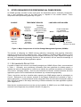
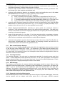
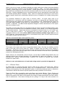
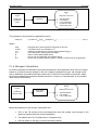
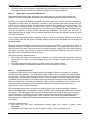
An OSMS generally consists of three main parts: the wastewater source, treatment components,
and a land application area for the final reuse or disposal of the treated effluent. These
components are represented graphically in Figure 1.
SOURCE
TREATMENT DEVICES
Collection/
Primary
treatment
Flush toilet,
Kitchen,
Bathroom,
Laundry
Secondary
treatment
(improves effluent
quality prior to land
application)
Septic tank,
Greywater
tank, AWTS
Sand filter,
AWTS,
Reed bed
LAND APPLICATION AREA
Reuse
Disposal
Evapo-transpiration
e.g. subsurface
irrigation, ETA beds
Absorption
e.g. absorption
trenches, ETA beds
Figure 1: Major Components of On-Site Sewage Management Systems (OSMSs)
The process of designing an OSMS involves gathering, interpreting and reporting information
relevant to each part of the treatment train. Thus, designing a suitable OSMS requires a good
understanding of the soils and other physical variables of the site (e.g. slope, aspect and shape of
the land), the wastewater generating activities of the household, and an extensive knowledge of
the available treatment and land application options.
2.1. RECOMMENDED DESIGN STEPS
A number of steps are involved in successfully designing an OSMS in Byron Shire, as summarised
in Table 1. Generally, once preliminary information has been gathered via desktop search, a
detailed site and soil assessment is carried out to identify any potential constraints and limitations
of the site for managing effluent. Once the site limitations are known, suitable treatment and land
application options can be identified that will address any constraints appropriately.
Table 1 should be used as a checklist when preparing an OSMS design report for submission to
Council. References to the relevant sections of the Design Guidelines are provided in Table 1
where appropriate. A computer-based model (using MS Excel) has also been developed by Byron
Shire Council to assist in the design and sizing of effluent treatment and land application systems
(refer Appendix C).
Note that the requirements that must be met by installers of OSMS (once an OSMS design has
received Council approval) are provided in Section 10 (page 31).
Design Guidelines for On-Site Sewage Management for Single Households
Page 4
Byron Shire Council
Doc #491166
Table 1: Steps required in preparation of an OSMS design report for submission to Byron Shire Council
Step
Task
Relevant section of Design
Guidelines to refer to;
1
Undertake desktop research
Section 3.0 (page 5)
2
Identify wastewater sources and water utilising devices,
and estimate hydraulic loads
Section 4.0 (page 6); Appendix
C; OSMS Design Model.
3
Conduct detailed site and soil assessment to identify
potential limitations of the site and soil for accepting
effluent
Section 5.0 (page 8); Appendix
B and H.
4
Identify suitable treatment and land application options
and consult with client to determine preferred options
Section 4.5, Appendices A & B.
5
Design treatment system
Appendices A and C; OSMS
Design Model.
6
Determine the most suitable method of land application
system and calculate the size of the land application area.
Appendices B and C; OSMS
Design Model.
7
Measure and peg out proposed land application area.
Compile a diagram showing layout of proposed land
application area
Section 8 (page 27)
8
Compile the above information in a detailed design report,
including preparation of OSMS Management Plan for
homeowners
Section 8 (page 27),
9
Submit 2 copies of the report to Council for approval
Section 8 (page 27)
*
Once design has been approved, requirements for
installation by licensed plumber are set out in Installers
Requirements
Section 10 (page 32)
3.
Appendix G.
DESKTOP RESEARCH
Desktop research must be undertaken to determine the approval status of any existing systems,
Deposited Plan (DP) and Lot numbers (or BSC Parcel Numbers when known), flooding depths and
frequency, risk of disturbing acid sulphate soils, geology and soils of the area (see Table 4) using,
for example, Soil Landscapes of the Lismore-Ballina 1:100,000 Sheet by Morand (1994) and other
references as necessary.
All designers are urged to come to the Byron Shire Council counter in Mullumbimby to get a copy
of a selective GIS image of the subject property (ask for “OSM Layer”, small fee applies). This will
show the approximate buffer distances to waterways, proximity to registered water bores and cattle
tick dip sites, and slopes greater than 10 %. Approximate flood-levels are usually available but
unfortunately Council’s mapping is not accurate enough to confidently predict flood levels in some
areas and local information may need to be sought.
Design Guidelines for On-Site Sewage Management for Single Households
Page 5
Byron Shire Council
4.
Doc #491166
ESTIMATING WASTEWATER GENERATION
4.1. PREDICTED HYDRAULIC FLOW
For existing dwellings fitted with a water meter, an accurate estimate of household sewage
volumes can be obtained by monitoring the meter readings over a number of weeks when little or
no outside watering is occurring, or examining water usage reported on previous water bills during
wet periods. For new houses or where no meter readings are available, effluent generation rates
should be based on the potential maximum number of people that may inhabit the dwelling at any
one time. In Byron Shire, this is calculated on the basis of the number of bedrooms multiplied by
1.5 persons per bedroom, unless there is information to suggest that more people will be or are
living there, in which case the higher number should be used.
Installing water efficient fittings and appliances in the household to minimise wastewater
generation rates can achieve significant reductions in the size and cost of treatment and land
application components of OSMS. Installing composting toilets rather than flushing toilets can
achieve the greatest single reduction.
In consultation with the home-owner, the OSMS designer is required to refer to AS1547 (2000) to
determine appropriate wastewater generation rates, based on what the household water source will
be (e.g. tank water or reticulated supply) and whether water-saving devices are installed. Note that
Council will need to confirm that any water-saving devices claimed in the design are installed when it
inspects the OSMS (refer Section 10). The daily volume of household effluent that the OSMS will
need to cater for is then estimated by multiplying the number of persons expected to reside there
(see above) with the expected effluent generation rate from AS1547 (2000). These calculations are
performed within a subroutine of the Byron OSMS Design Model (refer Appendix C).
4.2. NUTRIENTS AND PATHOGENS
Besides the volume of water, there are two other components of domestic sewage which need to
be closely considered by the OSMS designer; nutrients (e.g. carbon, nitrogen and phosphorus)
and pathogens.
4.2.1 Nutrients in Sewage
The often high levels of nutrients found in sewage can be either a potential source of pollution if
they are allowed to reach surface or groundwaters, or a resource in sustaining the growth of lawns
and gardens. As indicated in the Guiding Principles (Section 2.1), the challenge for the OSMS
designer is to reduce the nutrient levels and spread those that remain in the effluent in such a way
that they will virtually all be taken up by plants in the land application area and virtually no excess
nutrients will reach the groundwaters or neighbouring surface waters.
It is expected that compliance with these Design Guidelines, in conjunction with the associated
OSMS Design Model or an equivalent, will enable home-owners to be confident that they will not
be causing pollution by allowing excess nutrients to leave their property boundaries or enter
waterways. In most cases, this is achieved by matching the likely loads with plant uptake rates
and sizing the land application area (LAA) to ensure complete reuse within that LAA. On larger
blocks where the cumulative risks of OSMS are lower, Council’s OSMS Design Model permits a
proportional reduction of the LAA, with the expectation that the buffering capacity of the vegetated
lands surround the LAA will assist in assimilating any excess nutrients (refer Appendix C).
4.2.2 Pathogens in Sewage
Pathogens are micro-organisms that can cause diseases, including bacteria, protozoa, viruses and
helminths. Pathogens are found in varying concentrations in all domestic sewage, but are found in
particularly high concentrations when one of more of the residents are infected with a disease.
Design Guidelines for On-Site Sewage Management for Single Households
Page 6
Byron Shire Council
Doc #491166
Similarly, if pathogens are transmitted they might have no effect on a healthy adult but can be
much more of a risk for small children or immunity-suppressed receptors. Another related point to
note is that OSMSs servicing those who are taking strong medication, e.g. antibiotics and
chemotherapy drugs, are liable to be affected and maybe disabled by these medications.
Some types of pathogens, e.g. viruses and helminths, are able to survive outside the body for
months (refer for example to DLG, 2001 – OSRAS Handbook Appendix F). Although soil often
performs as a very good filter for pathogens, there always remains some risk that pathogens can
be transmitted from carelessly treated or inappropriately applied land application systems.
Based on available published information, Byron Council expects that adherence to these Design
Guidelines will ensure that risks posed to home-owners and neighbours are kept to acceptably low
levels. However, where designers have cause to reduce the recommended buffer distances (refer
Section 5.1.6) or where above-ground application of effluent is proposed (refer Section 7),
designers are required to provide additional written consideration to the risks of pathogenic
transport and potential infection by householders, neighbours or downstream water users.
Design Guidelines for On-Site Sewage Management for Single Households
Page 7
Byron Shire Council
5.
Doc #491166
SITE AND SOIL ASSESSMENT
Correct and accurate site assessment is critical to developing appropriate and sustainable sewage
management systems. The main aims of the site and soil assessment are to identify any
constraints that may potentially limit the ability of the site to adequately deal with effluent and to
determine the amount of suitable land available for land application of the treated effluent. The
information gained from the site and soil assessment will ultimately be used to determine the type,
size and location of the land application system, and the level of treatment required to overcome
any constraints.
Different situations require different levels of assessment, especially where there are limitations to
be surmounted. It is stressed that site and soils assessment are specialised disciplines and it is
not possible to include in these Design Guidelines all the relevant and necessary information that
professional assessors are required to understand (refer Section 1.3 for further information).
The following sections explain in detail the various parameters required for a site and soil
assessment. If constraints are found during the site and soil investigations, designers should
examine options for ameliorating these constraints (refer Table 6).
5.1. SITE EVALUATION PROCEDURES
Most of the following information is drawn from the Australian Standard (AS/NZS1547, 2000). The
information below will help you evaluate your site’s capacity to manage on-site sewage (Table 9).
5.1.1 Slope Angle (Refer also AS/NZS1547, 2000)
The slope of the site, especially the proposed application area(s), should be determined in the field
through the use of such instruments as an inclinometer over at least 20 m distance or through a
formal survey of the site.
Slopes greater than 15% (8.5 degrees) are regarded as severely limiting the installation and
operation of land application systems (refer Table 6).
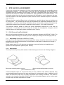
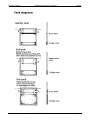
5.1.2 Slope shape
The shape of the slope may either assist or hinder drainage as shown in the following diagrams
Best water-shedding shape (convex)
Worst water-shedding shape (concave)
(Source AS/NZS1547, 2000)
Concave-shaped slopes are much more likely to have problems with effluent dispersal than
convex-shaped slopes because of the way groundwater is concentrated in them. Additional cut-off
drains and diversion bunds may be used to ameliorate poor drainage conditions. The reader is
referred to the Australian Standard (AS1547, 2000) for more detailed diagrams of the various types
of slope shape and their implications for OSMS.
Design Guidelines for On-Site Sewage Management for Single Households
Page 8
Byron Shire Council
Doc #491166
It is strongly recommended that the site be surveyed to aid landform and slope assessment. A
minimum distance of 20 meters will be required to measure and determine the degree of slope,
and variations in slope around relevant parts of the property should be marked on the plan.
5.1.3 Aspect
Use a compass to ascertain the dominant direction that the proposed irrigation area faces. North
and northeast-facing slopes are preferred due to greater exposure to sunlight, hence higher evapotranspiration rates. Refer to AS/NZS1547 (2000) for further advice.
5.1.4 Exposure
High exposure to sunlight and prevailing winds greatly aids the uptake of water vapour through
transpiration and evaporation processes. It is worth noting that meteorological stations are
invariably located in positions fully exposed to sun and wind. The daily water balance model
recommended in these Design Guidelines (Appendix C and OSMS Design Model), which are
based on Alstonville climate records, would not be representative of a damp shaded area. Any
such areas should be marked on the site plan and avoided in the selection of the land application
area. Refer to AS/NZS1547 (2000) for further advice.
5.1.5 Boulders/Floaters/Rock Outcrops
Boulders/floaters or rock outcrops may reduce the effectiveness of effluent “polishing” mechanisms
in the soil. Rocks make installation more difficult and may also restrict infiltration and allow sewage
to short-circuit the dispersal field and more rapidly enter waterways. (Refer also AS/NZS1547,
2000)
Proposed application areas should be traversed on foot and the presence of any boulders/floaters
or rock outcrops should be recorded in the site plan. Note: The definition of a boulder is a rock
whose middle dimension is at least 600mm (see Glossary).
Shallow bedrock is a significant constraint because it greatly limits the natural assimilation
capacities which might otherwise be provided by clay soils, and may provide a much faster and
much more poorly filtered conduit to groundwater resources. Where investigations indicate that
the C-horizon (weathered bedrock) lies within 1.5m of the soil surface, the depth to bedrock should
be entered into LAA calculations (e.g. in cell B14 in Byron OSMS Design Model) and amelioration
measures should be considered to compensate for the constraint (refer Table 6).
5.1.6 Buffer Distances
Accurate distances to certain critical features must be recorded as described below. Appropriate
setback distances are determined by the E&HP Guidelines (1998) or the Beavers and Gardner
method, described in their published paper (Beavers and Gardner, 1993). It is likely that there will
be difficulties in obtaining the necessary parameters (i.e. accurate estimations of soil permeability)
to use the Beavers and Gardner method however, in which case the default setback distances set
out below should be used.
Byron Council accepts that the following buffer distances cannot always be met. Where it is
necessary, or for some reason highly desirable, to reduce the one or more of the buffer
requirements, greater attention shall be paid to improving quality of the effluent or expanding the
size of the land application area (Refer Table 6). Where it is proposed to place the treatment
system or land application area within the following buffer distances, the designer must provide a
written evaluation of the potential risks for the transfer of pathogens from the OSMS to residents or
neighbours (refer Section 4.2.2) and proposed amelioration measures to be taken to reduce health
and environmental risks in the reduced buffers:
1.
minimum buffer distance of one hundred (100) metres from the nearest edge of permanent
watercourses including rivers, creeks, wetlands, dams or lakes.
Design Guidelines for On-Site Sewage Management for Single Households
Page 9
Byron Shire Council
Doc #491166
2.
minimum buffer of forty (40) metres from the centre-line of ephemeral water courses (e.g.
intermittent waterways, drainage channels and dry gullies).
3.
minimum buffer of 250 metres to downstream or cross-gradient domestic groundwater well,
and at least 50 m from upstream groundwater well.
4.
minimum buffer distances between the treatment and/or land application area (LAA) other
than ETA beds and a building or property boundary are as follows:
(i)
for sites with slopes less than 10% (5.7 degrees):
a)
three (3) meters when the building or boundary is up-gradient of the LAA; and
b)
six (6) meters when the building or boundary is down-gradient from the LAA; and
c)
1.5 meters between adjoining subsurface application systems (e.g. ETA beds); and
d)
six (6) meters from a swimming pool, driveway, building or property boundary;
5.
minimum buffer distances between the treatment and/or land application area (LAA) for ETA
beds should be double those listed above (e.g. 6 m if building or property boundary is upgradient of the LAA, and 12 m if it is down-gradient from the LAA)
6.
effluent dispersal fields/distribution networks (i.e. pipes, gravel, etc.) should be located a
minimum of 1200 millimeters above the top of the natural ground water table. This depth may
need to be increased to account for highly permeable soils, low-quality effluent and/or potential
sensitive environmental impacts;
6.
areas of high water table (i.e. less than 1.2 m below ground surface), groundwater recharge,
highly permeable soils and/or containing rock outcrops, shallow bedrock, acid sulfate, sodic or
saline soils are considered major limitations to onsite effluent dispersal.
7.
treatment and application systems should be kept at least 100 m from Cattle Tick Dip Sites or
other known contaminated sites, unless detailed soil sampling confirms that there are no
contaminated soils in the treatment or application areas.
5.1.7 Run-on and Upslope Seepage
Any known run-on or upslope seepage which might affect the application areas must be recorded
on the site plan (refer AS/NZS1547, 2000). The presence of flood debris and silt deposits may
assist in identifying run-on flowpaths. If stormwater cannot be reliably controlled by the construction
of a catch drain, a diversionary swale or an interception trench above the dispersal field, then an
alternative location must be chosen.
5.1.8 Flooding Potential
The flooding potential of the site must be determined, especially for low-lying areas and flood
plains. All land application areas should be above the 1 in 20 year flood height, and treatment
systems should be above the 1 in 100 year flood level. Council or the NSW Department of Public
Works may be able to supply flood height records in some areas.
5.1.9 Site Drainage
The frequency and duration of seasonal shallow waterlogging should be noted. Signs of poor
drainage include hard packed soils, vegetation growth characteristic of damp sites, and pooling of
water. It is not recommended that land application areas be installed within sites with poor
drainage. The location of channeled (concentrated) runoff on site, as well as any runoff likely to
move onto neighboring properties, should be noted on the site plan (refer also AS/NZS1547, 2000)
and avoided in the siting of the Land Application Area.
5.1.10 Vegetation Indicating Waterlogging
While wetland species such as bulrushes etc are obvious signs of frequent waterlogging, other less
obvious species such as sedges and buffalo grass can, in this region, indicate seasonal
Design Guidelines for On-Site Sewage Management for Single Households
Page 10
Byron Shire Council
Doc #491166
waterlogging. The presence of these or other moisture-loving species should be noted in the site
plan.
5.1.11 Surface Condition
Note cracks, hardness, previous compaction patterns, dampness and the location of seepage
areas (refer also AS/NZS1547, 2000).
5.1.12 Fill
The location, depth and type of any fill should be noted on the site plan, as shown in AS/NZS1547
(2000). Clean fill consisting of soil, which has settled and is on a stable site, may be used for
effluent application. However other types of fill with coarse fragments and located on steep sites,
are unsuitable for land application of effluent.
5.1.13 Erosion/Mass Movement
The location and details of existing mass movement and erosion, such as gullies, slips and rills
should be recorded on the site plan (refer AS/NZS1547, 2000). To protect against future erosion,
adequate drainage controls must be undertaken to ensure that effluent is not concentrated within
one location, and upslope runoff is diverted around the land application area.
Particular attention should be paid to ensuring that on-site systems in steep areas will not lead to
slumping on slopes. If in doubt, seek suitably qualified advice.
5.2. SOIL EVALUATION
The relevant soil properties of each proposed land application area should be investigated and
assessed in accordance with AS1547 and these Design Guidelines by a suitably skilled and
qualified, independent practitioner. The assessment must contain an accurate estimation of the
soil and sub-soil characteristics. The three key tests to be performed are
• the manual bolus or ribbon test to determine soil texture
• the visual test to determine soil structure
• the modified Emerson Aggregate test to determine soil dispersiveness
Soil evaluation needs to be focused on the proposed land application area as recommended in
AS1547 (2000). At least two soil profiles should be examined in each land application area, either
by boring or trenching. If significant differences are found in the first two profiles, more sampling
should be undertaken in order to establish the approximate boundaries of the various soil types.
Soil profiles should be examined to a depth of at least 1.2 m, or deeper if changes in soil colour or
texture are still being noted at the base of the hole. Unless there are less permeable layers found
during the profiling, samples from around 0.4 m depth and around 1.0 m should be collected for
detailed textural assessment, either by an independent geotechnical laboratory or by a skilled
practitioner. A single sample from around 0.8 m depth in the centre of the proposed land
application area may be acceptable in deep krasnozems, sands or particularly evenly graded soils.
Soil texture and structure determine the soil's ability to accept effluent, which in turn determines the
appropriate effluent loading rate. For example, highly dispersive soils are problematic due to the
damaging effect that excessive sodium can have in destroying the soil structure, leading to a
decrease in soil permeability, and very low effluent loading rates are therefore recommended for
highly dispersive soils (refer Section 8). Designers should also be aware that, even though they
are not classified as highly dispersive, krasnozem and many other volcanic-derived soils in this
area are prone to exhibiting reduced permeability after prolonged contact with highly sodic sewage
effluents (Patterson, 1998).
An indication of the broad soil category of a site can be obtained from Soil Landscapes of the
Lismore-Ballina or Tweed 1:100,000 Sheet Morand (1994). However, soil parameter values within
any one soil type can be highly variable. As part of the initial desk top study the soil unit from this
Design Guidelines for On-Site Sewage Management for Single Households
Page 11
Byron Shire Council
Doc #491166
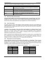
text should be ascertained in order to identify likely site and soil limitations as well as indicate likely
phosphorous sorption rates. Table 2 will assist in this process.
Table 2: Soil Landscapes in Byron Shire (showing likely limitations for effluent dispersal, and
phosphorous sorption. Sources: Morand (1994), P-sorption analyses by EAL, Southern Cross University 1998.
Soil Unit
Code
(Morand
(Morand, 1994) 1994)
Broad Soil Type
Bagotville
Bangalow
Ba
Bg
Sandy Duplex
Red Basaltic
Billinudgel
Bi
Black Rock
Coolamon
Br
Co
Yellow and red
podzols
Sandy podzol
Red Basaltic / Dark
Basaltic
Alluvial (highly
reactive)
Red Basaltic
Disputed Plain Dp
Eltham
el
Ewingsdale
ew
Mount Burrel
mb
Minyon
mi
Mullumbimby
mu
Myocum
North Casino
nc
Nightcap
ni
Nimbin Rocks
Nr
Rosebank
Ro
Terania
te
Tuckean
Tyagarah
tu
ty
Wollongbar
wo
Likely limitations
Asterisk (*) indicates comments from Morand
(1994)
Flood prone footslopes*.
Steep, shallow*. May need benching and/or
SDI on slopes.
Acidic, hardsetting soils, mod. CEC
Waterlogging, high watertables, low CEC*.
Steep, shallow, stony soils, mass movement*.
Waterlogged, impermeable soils, high
watertables*.
Locally waterlogged, flood hazard, proximity to
streams. *
Red Basaltic
High permeability, but mass movement hazard
near drainage lines, waterlogging on lower
slopes.*
Red Basaltic / Dark Steep slopes, mass movement*. May need
Basaltic
benching and/or SDI on slopes.
Sandy / Clayey
Steep slopes, rockiness, seasonal
Duplex
waterlogging and shallow soils (all localised)*
Alluvial clays
Flood hazard, seasonal waterlogging, high
watertables. May need mounds.
Alluvial clays
Flood hazard, seasonal waterlogging, high
watertables. May need mounds.
Alluvial (highly
Shrink-swell soils, localised waterlogging and
reactive)
high watertables*.
Varied: includes Red Steep slopes, mass movement, rockiness*
Basaltic, Clayey
Duplex
Steep thin volcanic
Severe limitations for development on cliffsoils
footslopes. Not suitable for OSMS.
Red Basaltic
Steep slopes, mass movement*. May need
benching and/or SDI on slopes.
Alluvial (varied, not Close to watercourse, flooding, stream-bank
highly reactive, and erosion, slumping*.
doesn’t easily fit
Great Soil Group or
profile categories)
Humic Gley
Unsuitable for effluent dispersal.
Alluvial /Sandy
Waterlogging, high watertables, low CEC*.
Podzolic
Red Basaltic
High permeability*.
P-sorption
kg/ha/m
(Morand,
1994)
8,000
10,000
10,000
1,000
10,000
10,000
10,000
10,000
10,000
8,000
10,000
10,000
10,000
8,000
--10,000
10,000
1,000
10,000
5.2.1 Soil Texture Classification
Soil texture may be measured by the behavior of a small amount of soil, incrementally moistened
and kneaded into a small ball (bolus), then manipulated between the thumb and forefinger to form
a ribbon. The soil is then categorised from the behavior of the moistened bolus and the length the
squeezed ribbon achieves before shearing or failing
There are six broad texture categories which are used to classify the likely permeability of soil, as
set out in Table 3. Each texture group and any change in texture group within the soil profile
Design Guidelines for On-Site Sewage Management for Single Households
Page 12
Byron Shire Council
Doc #491166
should be recorded. The following table is provided to assist in determining the soil texture
category.
Table 3: Soil Texture Grades. Source: Northcote (1979) and AS/NZS1547(2000).
Soil Category
(Texture Group)
Grade of Soil
Texture
Sand
1 - Gravels &
sands
Loamy sand
Clayey sand
Sandy loam
2 - Sandy loams
Fine sandy loam
Light sandy clay
loam
Loam
Loam, fine sandy
3 - Loams
Silt loam
Sandy clay loam
Clay loam
4 - Clay loams
Silty clay loam
Fine sandy clay
loam
Sandy clay
Silty clay
5 - Light clays
Light clay
Light medium clay
Medium clay
6 - Medium to
heavy clays
Heavy clay
Behavior of moist bolus
nil to very slight coherence, won’t mould,
single grains adhere to fingers
slight coherence
slight coherence, sticky when wet, many
sand grains stick to fingers, discolours
fingers with clay stain
bolus just coherent, v.sandy to touch,
dominant sand grains readily visible
bolus coherent; fine sand can be felt and
heard when manipulated (clearly seen
under hand lens)
strongly coherent bolus, sandy touch, med.
size sand grains easily visible
bolus coherent, spongy, smooth (not sandy
/ silky) feel when manipulated
bolus coherent and slightly spongy, fine
sand can be felt and heard when
manipulated
coherent bolus; very smooth to silky when
manipulated
strongly coherent bolus, sandy touch, med.
size sand grains in finer matrix
coherent plastic bolus, smooth
coherent smooth bolus, plastic and silky to
touch
coherent bolus, fine sand can be felt and
heard when manipulated
plastic bolus; fine to med. sands seen, felt
or heard in clayey matrix
plastic bolus; smooth and silky to
manipulate
plastic bolus; smooth to touch; slight
resistance to shearing between thumb and
forefinger
plastic bolus; smooth to touch; slightly
greater resistance to shearing between
thumb and forefinger.
plastic bolus; like plasticine & can be
moulded into rods without fracture; some
resistance to ribboning shear.
Smooth plastic bolus; like stiff plasticine;
can be moulded into rods without fracture;
firm resistance to ribboning shear.
Indicative
ribbon
length before
failure (mm)
Less than 5
≤ ~6.35
6.35-13
13-25
13-25
20-25
~ 25
~ 25
~ 25
25-38
38-50
38-50
38-50
50-75
50-75
50-75
~ 75
≥ 75
≥ 75
5.2.2 Soil Structure
The soil structure is to be determined from visual assessment of the site and from borehole testing,
through the examination of exposed soil surfaces. Table 4 summarises the common soil
structures.
Design Guidelines for On-Site Sewage Management for Single Households
Page 13
Byron Shire Council
Doc #491166
Table 4: Soil structure according to degree of pedality. Source (AS/NZS1547, 2000)
Degree of Pedality
Massive
Single grained
Weak
Moderate
Strong
Appearance
Coherent, with any partings both vertically and horizontally spaced at
greater than 100 mm. Pieces do not break along planes of weakness but
break according to stress loads
Loose incohesive, structureless e.g. sands
Peds indistinct and barely observable on pit face. When disturbed
approximately 30% consist of peds smaller than 100mm
Peds well formed and evident.. but not distinct in undisturbed soil. When
disturbed 30% - 60% consists of peds smaller than 100mm
Peds quite distinct in undisturbed soil. When disturbed >60% consists of
peds smaller than 100mm
5.2.3 Soil Permeability Determination
Accurate soil permeability assessment is encouraged but is often quite problematic. A preferred
method for field evaluation using a constant-head permeameter is provided in Appendix 4.1 F of
AS/NZS1547 (2000). Alternatively, AS 1547 (2000) provides indicative permeabilities based on
textural and structural soil characteristics (refer Appendix 4.2 of AS1547 cited above).
5.2.4 Colour Description
The colour of a soil is often a good indicator of state of saturation of the soil, in turn reflecting the
oxygen availability in the soil. For example, red or brown colours generally indicate well aerated
soils lying above the standing water table, while grey or white soils are often found in saturated or
periodically saturated soils.
A detailed colour description of the soil profile should therefore be conducted during the soil
assessment. The soils should be described in the moist condition by the following colours: black,
white, grey, red, brown, orange, yellow, green or blue. The classification can be modified as
required by the words pale, dark or mottled. Transitional colours may be described as a
combination of these colours (e.g. red-brown).
When a soil horizon has a predominant colour with mottles of another colour, it is described in the
form: (predominant colour) mottled (secondary colour), e.g. grey mottled red-brown. Where two
colours are present in roughly equal proportions, the colour description is described in the form:
mottled (first colour) and (second colour), e.g. mottled brown and red-brown.
5.2.5 Assessment of Coarse Fragments
Coarse fragments include hard rock material and nodules or segregations. These may be
separated from the fine earth component of a soil sample by using a 2 mm sieve. This is a difficult
process when a soil is moist and heavy, in which case a field estimate using abundance charts is
acceptable. A visual estimate of abundance should be recorded, along with the size range of rock
fragments and their corresponding amounts, using Table 5a and 5b.
Table 5. Abundance (a) and Size (b) of Coarse fragments
Class
Very few
Few
Common
Many
Abundant
Profuse
% of coarse
fragments
<2
2-10
10-20
20-50
50-90
>90
Type of rock
Fine gravel
Medium gravel
Coarse gravel
Cobbles
Stones
Boulders
Source: (AS/NZS1547, 2000)
Size of coarse
fragments mm
2-6
6-20
20-60
60-200
200-600
>600
Design Guidelines for On-Site Sewage Management for Single Households
Page 14
Byron Shire Council
Doc #491166
Where coarse fragments occupy more than 20% of soil volume and larger pores correspondingly
accompany these coarse fragments, the flow of water is not expected to be impeded. Where
coarse fragments occupy more than 20% of the soil volume but large pores accompanying the
larger fragments are not present, the water flow is expected to be impeded and the Soil Category
should be increased by one class e.g. a Clay Loam should be classed as a Light Clay for
permeability estimation purposes.
Where there are more than 20% cobbles, stones and boulders, this can impede surface
preparation and excavation and contribute to trench collapse.
5.2.6 Field pH
The pH of a soil can alter the availability of nutrient elements for plant uptake and can cause metal
toxicities if pH is too low or too high. Acid soils tend to be leached of major plant nutrients e.g.
calcium, magnesium, nitrogen and possibly molybdenum, while phosphorus may not be present in
plant-available form. Alkaline soils are often deficient in iron, manganese, copper or zinc (Morand,
1994). A field pH test, using a calibrated field instrument or colour-test-strips, should be undertaken
to determine the acidity/alkalinity of the soils. Soil pH of between 6.5 to 8 is ideal for plant uptake
of phosphorous, potassium and nitrogen.
5.2.7 Dispersive Class (Modified Emerson Aggregate test)
The Modified Emerson Aggregate test provides a simple field assessment of a soil’s aggregate
stability. It is carried out using effluent or a prepared solution with similar qualities as the effluent to
be applied to the soil being tested (for septic tank effluent this is equivalent to a solution with
Sodium Absorption Ratio (SAR) of 5 and EC around 1000 µS/cm) (Patterson, 1998).
The test involves placing about three 5mm diameter undisturbed soil aggregates from the soil
profile into a beaker of the above solution, and leaving undisturbed for 24 hours. The behavior of
the aggregates is then recorded from the following:
Class 1: Material disperses completely.
Class 2: Aggregates disperse (clouds solution appreciably)
Class 3: Aggregates slake - smaller aggregates/particles fall off the original aggregate
Class 4: No change to aggregate, therefore non-dispersive.
If any of the replicates are in Classes 3 or 4 then the soil shall be considered dispersive and the
Soil Category should be considered Grade 6, as though for a Texture Grade of Medium to Heavy
Clays (refer Table 3 above and AS/NZS1547, 2000 for further information). In such cases, gypsum
will need to be worked into the land application area at a predetermined rate in order to prevent soil
structure degradation. Further ameliorative measures, such as the expansion of the land
application area or provision of a larger reserve field, is also likely to be required to compensate for
the likely long-term reduction in permeability in the land application area.
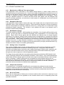
5.3. SITE CONSTRAINTS AND POSSIBLE SOLUTIONS
The information in preceding sections should be used to make an assessment of the proposed
land application area(s), and to identify any constraints for treatment or dispersal of effluent.
Should any site or soil limitations be found, applicants or their consultants must clearly report them
in the assessment report, highlighting all limitations and detailing the appropriate mitigation
measures intended to be taken to address these limitations. Tables 6 and 7 show some common
site and soil constraints, and the measures which might be employed to overcome them or
ameliorate their effects.
Design Guidelines for On-Site Sewage Management for Single Households
Page 15
Byron Shire Council
Doc #491166
Table 6: Limiting Site Conditions for Land Application Areas and Suggested Solutions
Site Feature
Examples of limiting conditions
Slope
For steeper ground use
narrow ETA beds or SSI
Slopes >15%
Landform
Convergent (drainage-concentrating)
land shape
Exposure
Good aspect and exposure
to sun enhances
evapotranspiration rates
Land application area faces SW or SE
quadrants, and/or trees sheltering from
sun-wind
Distance to Water Body
and man-made features
Potential for polluting
downstream waters or
neighbouring properties
Run-off/seepage from
upstream lands
Flooding Potential
<100m to permanent surface water
OR
<250m to domestic groundwater wells
OR
<40m to other waters (e.g. farm dams,
intermittent waterways, dry gullies and
drainage channels)
OR
<6m if up-gradient and <3m if downgradient of property boundaries,
swimming pools, driveways and
buildings
(In the case of ETA beds:
<12m if up-gradient and
<6m if down-gradient of property
boundaries, but 6m/3m as above for
pools etc)
Run-on periodically saturates Land
Application Area.
Land application area below 1 in 20
year flood contour
OR
Treatment system below 1 in 100 year
flood contour
Site Drainage
Signs of surface dampness
Vegetation indicating
waterlogging
Presence of sedges etc that indicate
waterlogged soil
Surface Condition
Bare ground or cracking
Fill
Land application area contains fill
Erosion/Mass Movement
Rills, slips
Suggested solutions
to limitations
Enhanced treatment, sub-surface
irrigation over larger area. Irrigation
with wider spaced SDI emitters
along contour for very steep or
highly constrained sites.
Stormwater diversion bunds above
concentrating areas, larger
application area.
Shade plants trimmed often,
expand land application area or
improve effluent.
Enhanced treatment of effluent,
expand land application area,
ensure that drainage is diverted
around land application area.
Swales, diversion drains,
subsurface drainage.
Pump and electrical components
must be out of 1:100 year flood
zone, consider SDI with wetweather storage or raised
application area (e.g. mounds).
If due to shading, trim trees or find
alternative area. If due to
stormwater, adjust surface drainage
Swales or diversion drains to
control drainage, improve
treatment, expand application area
or use raised mounds.
Add or amend surface soils,
improve treatment.
Attempt to find alternative area, or
replace fill with stable, compacted
mixture of sand and clay soil.
Ensure geotechnical stability will
not be compromised by effluent
Promote vegetation growth,
improve drainage, get geotechnical
advice.
The following table provides a summary of common soil problems which may be encountered in
Byron Shire, with an indication of when the soil characteristic may limit on-site effluent dispersal,
and possible amelioration measures for constrained land application areas.
Design Guidelines for On-Site Sewage Management for Single Households
Page 16
Byron Shire Council
Doc #491166
Table 7: Soil limitations and suggested solutions
Soil Feature
Dispersive or swelling
Soils using modified
Emerson Aggregate test
Coarse Fragments(Coarse
fragments, rocks, boulders
impede absorption)
Field pH
Soils in proposed land application area
found to be dispersive (i.e. Class 3 or 4
in Table 4.1.1 of AS1547:2000),
sodic or prone to shrink-swell
characteristics.
Rock fragments occupy >20% of soil
volume
pH < 5.5 or >8
pH extremes inhibit plant
growth
Suggested solutions
to limitations
Examples of limiting conditions
Add gypsum or otherwise amend
soil. Improve or increase secondstage treatment, and/or increase
application areas.
Increase size of land application
area proportionally.
Improve or increase second-stage
treatment. Conditioning with lime
may assist if pH<5.5
Design Guidelines for On-Site Sewage Management for Single Households
Page 17
Byron Shire Council
6.
Doc #491166
CHOOSING A TREATMENT SYSTEM
This section provides information to assist in selecting the most suitable treatment system that will
satisfy the needs of the given homeowner and adequately deal with any site constraints (such as
close proximity to waterway or small block size). For each treatment system, general information
is given regarding its function and form, and important information relevant to the operation and
maintenance of each system is provided.
More detailed information for use in the design and sizing of each treatment system is provided in
Appendix A. Designers are also strongly encouraged to do further reading and research (e.g.
Crites & Tchobanoglous,1998; Metcalf & Eddy, 2002) to ensure that they understand all relevant
aspects of all treatment systems under consideration. Applications based on innovative designs or
emerging technologies are encouraged, provided sufficient technical justification can be provided
to support their stated performance expectations.
Designers and prospective owners should be aware that each system will require some monitoring
and maintenance, specified by Byron Shire Council in the Approval to Operate for that sewage
management system (refer Appendix G). Highly mechanised systems such as aerated
wastewater treatment systems and sub-surface irrigation fields generally have quarterly
maintenance requirements, whilst most other systems need to be checked and maintained by a
suitably skilled service-provider at least once a year. Designers and prospective owners should
ensure that they are aware of the monitoring and maintenance requirements and consider their
costs when choosing the system.
6.1. SOURCE CONTROL
6.1.1 Water-Saving Devices
The size and cost of treatment and land application systems are directly related to the volume of
effluent that must be dealt with. Thus, activities or devices that minimise the generation of effluent
at the source can often bring about a significant reduction in the cost and size of the OSMS.
Careful consideration should therefore be given to the water consuming appliances used in the
household (e.g. washing machines, flush toilets, shower heads, leaking plumbing).
Installing water efficient fittings and appliances in the household to minimise wastewater
generation rates can achieve significant reductions in the size and cost of treatment and land
application components of OSMS. Installing composting toilets rather than flushing toilets can
achieve the greatest single reduction.
The designer is then required to refer to AS1547 (2000) to determine appropriate wastewater
generation rates, based on what the household water source will be (e.g. tank water or reticulated
supply) and whether water-saving devices are installed. Note that Council will need to confirm that
any water-saving devices claimed in the design are installed when it inspects the OSMS (refer
Section 10). The daily volume of household effluent that the OSMS will need to cater for is then
estimated by multiplying the number of persons expected to reside there (see above) with the
expected effluent generation rate from AS1547 (2000). These calculations are performed within a
subroutine of the Byron OSMS Design Model (refer Appendix C).
6.1.2 Waterless Compost Toilets
Compost toilets significantly reduce the amount of treatment required for sewage by eliminating
faeces and urine from the wastewater stream at the source. By eliminating the need for toilet
flushing, they also reduce household water usage by as much as 30%. Consequently, the size
and complexity of the treatment component of the OSMS can be significantly reduced, as only
greywater is generated by the household. Nevertheless, it should be noted that compost toilets still
Design Guidelines for On-Site Sewage Management for Single Households
Page 18
Byron Shire Council
Doc #491166
generate a small amount of leachate that will need to be directed to the greywater management
system or a small trench.
Details regarding the design and functioning of composting toilets are provided in Appendix A5.
Operation and Maintenance advice is provided in Appendix G. All compost toilet installations shall
be strictly in accordance with the requirements of the Local Government Act 1993.
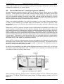
6.2. PRIMARY TREATMENT
Primary treatment refers to the physical removal of solids and organic matter through settling and
sedimentation. Collection tanks (i.e. septic and greywater tanks) for raw effluent provide significant
primary treatment through settlement and anaerobic digestion of organic solids by microbes.
Primary treatment results in an effluent that is lower in suspended solids and biochemical oxygen
demand (organic matter), but does not significantly reduce nutrient levels. The level of primary
treatment depends on the residence time of the sewage in the tank, which in turn depends on the
size of the tank, the volume occupied by scum and sludge layers and the volume of water used in
the house.
6.2.1 Septic Tanks
The septic tank operates as a small anaerobic digester. Septic tank effluent is much lower in
settled solids than the raw influent, but is still concentrated in nutrients and biochemical oxygen
demand and generally requires some level of secondary treatment before it is suitable for land
application (refer Section 6.3).
Additional information regarding the function, sizing and
management of septic tanks is provided in Appendix A. Operation and maintenance advice is
provided in Appendix G.
6.2.2 Greywater Treatment
“Greywater” (or sullage) is the term used for all household wastewater excluding toilet wastes, for
example the wastewater generated in a house with only composting toilets. Greywater generally
contains lower nutrients but can still contain significant levels of pathogens, e.g. from showering
and nappy washing. NSW Health requires that greywater be disposed of below ground level
unless it has been adequately disinfected.
Greywater must be collected in an in-ground sullage tank (sized in accordance with NSW Health
requirements, refer Appendix A), where primary treatment can occur, before being dispersed into
the soil. Where the site is unconstrained, it can be piped directly from the sullage tanks into a
suitably sized sub-surface land application system (refer Appendices B and C), but it should be
understood that this is likely to reduce the operational life of the land application system. Byron
Council therefore recommends that effluent from the sullage tank be further filtered and/or treated
before land application (e.g. in a reed-bed or sandfilter).
The size of the application area required to safely disperse of greywater depends on effluent
volumes and household inputs, and may be calculated using Byron Shire Council’s OSMS Design
Model (refer Appendix C). The minimum allowable size for a greywater dispersal bed must be
calculated based on the nutrient uptake and hydraulic capacity of the land application system, but
in no cases shall it be smaller than 10 m2 per person in the household. This minimum figure is
based on hydraulic dispersion capabilities of most soils, and would only be considered appropriate
for at least partial-secondary treated greywater (refer Section 6.3).
6.2.3 Effluent Filters
An effluent filter is a coarse screen filter that fits into the outlet of a primary treatment tank. Effluent
filters reduce Total Suspended Solids (TSS) carry over and thereby extend the operational life of
land application components. Effluent filters are required to be fitted on the outlets of both septic
and greywater tanks. Homeowners shall be made aware of the frequency and mode of cleaning
before a particular filter is selected (refer Appendix G).
Design Guidelines for On-Site Sewage Management for Single Households
Page 19
Byron Shire Council
Doc #491166
6.3. SECONDARY & PARTIAL-SECONDARY TREATMENT
For the purposes of these Design Guidelines, the term “secondary treatment” applies to systems
which produce effluents containing less than:
• 20mg/L BOD
• 30mg/L Total Suspended Solids
• 30 mg/L Nitrogen
• 10 mg/L Phosphorus
(Source: Dept Natural Resources, Interim Code of Practice for On-site Sewerage Facilities, 1999)
It is noted that the above performance standard is from Queensland, and that the equivalent
design standard in NSW does not provide criteria for nutrients, but the above criteria is
nonetheless offered in these Design Guidelines for additional guidance.
Council acknowledges that there are smaller treatment system options (e.g. smaller scale reedbeds), which will significantly improve the quality of effluent, but wouldn’t necessarily reach the
“secondary” performance standards listed above. For the purpose of these Design Guidelines,
these options are termed “partial-secondary” treatment systems (refer Glossary for definitions).
The minimum standard of treatment generally accepted for blackwater-inclusive OSMSs in
Byron Shire is to a partial-secondary standard which achieves a 20% reduction in total
nitrogen.
The choice of a treatment system to achieve secondary or partial-secondary effluent quality at any
given property will involve balancing the strengths and weaknesses of the available treatment
options, summarised in Table 8 and discussed in more detail in Appendix A. Constrained land
application areas, e.g. within stated buffer distances (Section 5.1.1) or on poor soils or steep
slopes, will generally require higher levels of treatment or larger land application areas to ensure
that pollution of waterways is avoided.
By reducing the concentration of nutrients and suspended materials, the level of effluent treatment
has a proportional impact on the size of the land application area required (as calculated by the
OSMS Design Model, see Appendix C). Homeowners and system designers have the option to
choose better quality (e.g. secondary) treatment and small land application areas, or lesser quality
(partial-secondary) treatment combined with larger application areas, provided that the partialsecondary treatment option achieves at least a 20% reduction in total nitrogen for blackwaterinclusive systems.
Design Guidelines for On-Site Sewage Management for Single Households
Page 20
Byron Shire Council
Doc #491166
Table 8. Strengths and weaknesses of secondary treatment systems. Source: Davison (2003)
Reed bed
Single pass
Recirculating
Performance criterion
AWTS
(horizontal
sand filter
sand filter
flow wetland)
Yes
Pump needed on Yes
No
Power required?
flat ground
Any
1m fall if no
Any
Flat to
Fall of site
pump
moderate
slope
Small
~ 4m2 /person
<3m2 /person
4-6m2 /person
Surface area
High –
Owner can do
Owner can do
Owner can do
Maintenance
quarterly
checks, annual
checks, annual checks, annual
contactor
contractor to
contractor to
contractor to
required
service
service
service
High
High
High
Moderate
Construction cost
Good
Good
Good
Poor to
Nitrification
moderate
Low
Low
Good
Moderate to
Nitrogen removal
good
No
Yes
Yes
No
Intermittent dosing
needed?
Low
Low
Moderate
Very good
Tolerance to peak
loads
Low
OK
OK
OK
Tolerance to low loads
(holidays)
Low unless
Can be hidden
Can be hidden Moderate, can
Visual impact
above ground
be landscaped
Awareness? Does the
No
No
No
Yes
device invite user
participation & hence
awareness/
commitment?
6.3.1 Aerated Wastewater Treatment Systems (AWTS)
Aerated wastewater treatment systems (AWTS) have become popular in recent years, and a range
of proprietary systems is available on the market. AWTS’s are small-scale package treatment
plants that are conceptually similar to large-scale sewage treatment facilities. They typically
produce an effluent which, with sufficient filtering, can be distributed straight into a subsurface
dispersal system (i.e. partial secondary effluent quality with 20% nitrogen reduction).
AWTS’s depend on steady-state microbiological conditions, reliable electrical supply and regular
maintenance of mechanical and electronic components to sustain reliable treatment. Failure or a
sustained interruption in any part of the system, e.g. as a result of power interruptions or when a
tourist dwelling is unoccupied during the off-season, can lead to a definite health and
environmental risk until sufficient microorganisms are once again restored to adequately treat the
effluent. Furthermore, AWTS’s require regular (quarterly) maintenance to ensure that adequate
disinfection (via chlorination) is maintained if this is required by their NSW Health Accreditation.
This is why Byron Shire Council will usually only approve sub-surface irrigation as the land
application method connected to an AWTS.
The sometimes high up-front and quarterly monitoring and maintenance costs associated with
AWTS must also be considered when choosing an AWTS. Maintenance requirements for AWTSs
are detailed in Appendix G.
Design Guidelines for On-Site Sewage Management for Single Households
Page 21
Byron Shire Council
Doc #491166
6.3.2 Sand Filters
Sand filters (or derivations using other media) are an alternative type of secondary treatment
device popular in the Europe and North America. Sand filters are generally of two types: singlepass and recirculating. Sand filters work best when the effluent is spread in even, pulsed doses
over the top of the sand-bed. This can be achieved under gravity using a dosing siphon if sufficient
static head (fall) is available, or more commonly by electric pump. Adequate primary treatment and
good filtering must be maintained to prevent too much carry over of suspended solids and
consequent clogging of the upper layers of sand media.
A disadvantage of some single pass sand-filters is their poor nitrogen-removing performance
(though good nitrifying capacity). This can be remedied either by deepening the filter to ensure an
anaerobic zone or by recirculating a proportion of the highly nitrified sand-filter effluent back over
the sand filter or into the carbon-rich septic tank for rapid denitrification (USEPA, 2003).
Recirculating sand filters usually provide better N-removing capability and better overall treatment
performance than single-pass sand filters. However they are more expensive and complicated to
construct, and require additional pump power.
More detail on the design and performance of sand filters is provided in Appendix A. Operation
and maintenance requirements for sand filters are provided in Appendix G.
6.3.3 Subsurface Flow Reed Beds (Constructed Wetlands)
Constructed wetlands, or reed-beds, comprise a constructed impermeable basin in which water or
effluent is kept slightly below the surface of a gravel substrate which supports the growth of
wetland plants (usually reeds but can also be shrubs or trees). The effluent is biologically treated
as it moves slowly through the root zone of the wetland plants.
Reed-beds are an increasingly popular type of secondary treatment device due to their aesthetic
appeal, their reliable treatment performance capacities once the reeds are fully established, and
their somewhat lower construction costs and maintenance requirements compared to other
options. They are also passive devices not necessarily reliant upon power or pumps, and therefore
economical to operate in the long term.
Details of reed-bed design requirements are provided in Appendix A. Sizing options for secondary
and partial-secondary quality effluents is incorporated into the OSMS Design Model. Operation
and maintenance requirements for sand filters are provided in Appendix G
6.4. TERTIARY TREATMENT
In domestic on-site sewage management, tertiary treatment is generally taken to mean disinfection
of secondary-treated effluent, but it may also include additional secondary treatment, filtration,
and/or nutrient removal.
6.4.1 Disinfection
There are a number of options for effective long-term disinfection for on-site systems. Chlorination
is commonly used with AWTS’s. Some systems use bromine, UV light or ozone to disinfect. For
surface spray or dripper-under-mulch irrigation systems, the effluent must be disinfected after
partial-secondary treatment. Subsurface irrigation requires partial-secondary or secondary
treatment, but does not require disinfection. NSW Health regulations require that disinfection of
AWTS effluent occurs in most cases, even for sub-surface applications.
Design Guidelines for On-Site Sewage Management for Single Households
Page 22
Byron Shire Council
Doc #491166
6.5. OTHER CONSIDERATIONS
6.5.1 Maximisation of Effluent Take-up by Plants
Land application areas calculated by the OSMS Design Model or similar means should be
considered minimum requirements only. Council encourages all applications to maximise re-use of
effluent into the filtering matter of plants, and any alternative applications that achieve a higher reuse than is required to comply with these design Design Guidelines are encouraged. Those
wishing to distribute effluent in a manner that best serves their garden, and still complies with
Council and State guidelines, are welcome to submit plans for consideration by Council that will
better meet this objective.
6.5.2 Phosphorus Removal
Land application areas located on sandy soils may need suitable soils to be imported into the land
application area to aid in phosphorus removal. Filters specifically designed to remove phosphorus
may be incorporated into secondary treatment devices (e.g. through the use of media with a high
phosphorus-sorption capacity). The media in such systems will need to be replaced once it
becomes saturated with phosphorus.
6.5.3 Wet-Weather Storage
The NSW guidelines (E&HPG, 1998) highlight the desirability of not irrigating effluent during wetweather, as this may lead to occasional surcharging and contamination of run-off waters with
effluent. Byron Shire Council agrees with this sentiment but believes that, for single domestic
applications, the expense, difficulty and increased risks to householders of contacting the effluent
often outweigh the potential health and environmental risks of effluent-contaminated run-off during
very wet periods. These Design Guidelines do not therefore mandate that wet-weather effluent
storage must occur in single domestic installations, but designers should consider wet-weather
storage a useful potential tool for improving environmental security on highly constrained sites (e.g.
flood-prone lands or those over shallow groundwaters).
6.5.4 Holding Tanks / Pump Wells
Many modern OSMS systems require pumping effluent to or from various components, and this
generally necessitates either an internal or external pump well. Pump wells, also commonly
referred to as holding tanks or collection wells, enable the storage of effluent until it reaches a preset level in the tank at which time a pump is activated and the accumulated effluent is pumped
through to the next component or the land application system.
The sizing of pump wells shall be in accordance with the advice provided by NSW Health in their
“Septic Tank and Collection Well Accreditation Guideline” (refer Section 1.4 for download address),
and provide sufficient storage space for at least seven days accumulated effluent in case of pump
failure or blockage. Smaller holding tanks are acceptable for dosing siphons which have no
opportunity for mechanical break-down. Audio and/or visual alarms must be installed in a manner
that will alert the homeowner to the presence of a high-level condition in the tank. Backflow
prevention devices must also be installed where appropriate.
6.5.5 Component Overflows
If overflows occur, it is important that effluent is not contacted by residents but also that the
overflow is visible and cannot be readily ignored for sustained periods. Council encourages the
installation of appropriately sized emergency overflow trenches, provided that inlets from the
component are not sub-surface connections.
6.5.6 Pit or Pan Toilets
Due to the risk these types of toilets pose to human health and the environment, simple pit or pan
toilets are now required to be upgraded to more suitable toilets such as composting toilets with
greywater treatment.
Design Guidelines for On-Site Sewage Management for Single Households
Page 23
Byron Shire Council
7.
Doc #491166
CHOOSING A LAND APPLICATION SYSTEM
Effluent quality plus site and soil-specific parameters largely determine the appropriate land
application system for any given situation, but cost and maintenance requirements are also clearly
relevant in making the necessary choices. The strengths and weaknesses of various land
application systems are summarised in Tables 4.2B1 and 4.2B2 of AS/NZS1547 (2000), whilst a
brief description of each option is provided in the following sections. Greater detail of each land
application system may be found in Appendix B, and maintenance requirements are
provided in Appendix G.
The sizing of the land application area may be calculated using the OSMS Design Model, as
outlined in Appendix C. Reserve application areas, with equivalent characteristics to the primary
field, shall be designated and set aside in all new applications. The reserve field may be required if
the primary application field fails over time due to, for example, reductions in permeability caused
by interactions with sodic effluent or the soil’s capacity to absorb phosphorus becomes supersaturated.
7.1. ABSORPTION TRENCHES
The traditional absorption trench is the archetypal “disposal-only” system. Because there is little
opportunity for reuse or treatment through plant uptake and because it is difficult to distribute
effluent evenly in a way that does not pollute in the long-term, traditional trenches are discouraged
in new OSMS installations. Systems which rely on soil absorption as the principal mechanism, e.g.
absorption trenches, generally do not comply with the requirements of these Design Guidelines or
the NSW EHP Guidelines 1998 (p119).
On some highly constrained lots where insufficient space is available for any other form of land
application, absorption trenches may be the only viable option for effluent dispersal. In these
cases, Byron Shire Council would generally expect that absorption trenches be preceded by at
least secondary treatment, and that all necessary efforts would be made to disperse effluent evenly
over the entire length of the trenches (e.g. by pumping or intermittently dosing).
On highly permeable soils which are located a sufficient distance above the standing water table
beneath, it may sometimes be acceptable to use a “discharge control trench”, in which the trench
beneath the distribution pipe is deepened and filled with washed sand (refer AS/NZS1547, 2000 for
design details).
On other types of highly constrained site (e.g. where only very small land application area is
available), it is sometimes appropriate to distribute effluent in “micro-trenches”. These microtrenches comprise narrow, shallow, gravel-filled trenches in which sub-surface irrigation pipes are
installed. The advantages of micro-trenches is that by shallowly laying them along the contour and
pumping the effluent into them, they can distribute effluent reliably, evenly and intermittently.
Assuming that stormwater is adequately diverted, micro-trenches provide a good opportunity for
reuse by plants and only a low risk of effluent surcharging during wet periods.
7.2. EVAPOTRANSPIRATION/ABSORPTION (ETA) BEDS
EvapoTranspiration (ET) and EvapoTranspiration/Absorption (ETA) beds are wider and shallower
than traditional absorption trenches, thereby providing a much greater opportunity for uptake by
plants and reduced dependence on infiltration and soil assimilation capacities to treat the effluent.
ET and ETA beds have a number of limitations, discussed in some detail in Appendix B3. Due to
these limitations and their relatively high expense, ET and ETA beds are not encouraged in Byron
Shire. If they are required to be installed, a great deal of care is required in their design and
installation to ensure that effluent is spread evenly over the entire bed space.
Design Guidelines for On-Site Sewage Management for Single Households
Page 24
Byron Shire Council
Doc #491166
Owners of ETA beds should maintain appropriate vegetation on the beds. Mowed grass is the
preferred vegetation cover, although shrubs and trees can be planted suitable distances away from
the edge of ETA beds (see Appendix B3 for details).
7.3. SUB-SURFACE DRIP IRRIGATION (SDI)
Sub-surface drip irrigation (SDI), also commonly referred to as sub-surface irrigation (SSI), is a
good means of distributing treated effluent because it can distribute small, measured doses to
evenly spaced centres in relatively undisturbed soil. This ensures a very reliable distribution
available for rapid root uptake, and minimises the risk of the irrigation field becoming saturated
during extended rainfall. Sub-surface irrigation is particularly appropriate where there are site or
soil limitations or limitations, such as steep slopes, on heavy impermeable (often termed “puggy”)
soils, and can even be used with care on highly permeable sandy soils.
Sub-surface irrigation systems must be designed and installed by suitably qualified persons, and
must be flushed to remove sediment/slime at least once per year, and preferably quarterly, by a
qualified professional as part of the maintenance requirements. Suitably located pressure-release
valves and flush pits must be provided to allow this regular flushing maintenance without causing
pollution.
There are a number of different types of proprietary SDI systems on the market. Council requires
that all new installations use pressure-compensated emitters, and strongly prefers the use of nondrain varieties. Additional details regarding design and operation of subsurface irrigation systems
is provided in Appendix B4, and operation and maintenance requirements are provided in
Appendix G.
7.4. SPRAY IRRIGATION
Above-ground spray irrigation requires prior tertiary disinfection of sewage (NSW Health). Within
the Byron Shire, spray irrigation of effluent is not favored due to public health risks from aerosoltransmitted pathogens and the particular need to add toxic substances (such as chlorine) to
disinfect the effluent before above-ground release. There may be some circumstances (e.g. on
larger agricultural holdings in which the proposed land application area is a considerable distance
from any houses, where spray irrigation may be accepted.
Refer Appendix G for maintenance requirements.
7.5. SURFACE DRIPPER-UNDER-MULCH IRRIGATION
Byron Shire includes productive farming area where effluent reuse can be particularly beneficial. The
irrigation of effluent by above-ground drippers in plantations may be appropriate in some rural and
reafforestation applications. Surface dripper-under-mulch options may be considered for domestic
situations in Byron Shire, but higher maintenance and monitoring conditions will be required to ensure
that the mulch remains in place over the drippers and that casual access by children, vehicles and
livestock is restricted by a vegetative border, fence or similar device. Disinfection of effluent is
generally required. Refer Appendix G for other maintenance requirements.
7.6. SPECIAL COMPONENTS USED IN LAND APPLICATION AREAS
Besides the components described above and in Appendix B, there are a number of important
auxiliary components which are generally found in land application systems:
7.6.1 Indexing Valves
Indexing valves allow for up to six (6) separate land application areas (beds or irrigation areas), to
be used. The indexing valve will apply a set volume of effluent to the first application area after
Design Guidelines for On-Site Sewage Management for Single Households
Page 25
Byron Shire Council
Doc #491166
which the pump turns off and the valve automatically switches to the next application area where
the process is repeated.
7.6.2 Dosing Siphons
Gravity-driven dosing siphons are becoming more popular in the North Coast region. These are
unpowered devices that ensure effluent reaches the treatment or dispersal system in a periodic
“slug” rather than a constant dribble, thus providing more even distribution and more successful
treatment and/or dispersal of effluent. Siphons are generally located after the collection tank (grey
or blackwater) and may be used to deliver effluent to sand-filters and/or ETA beds. They are
recommended in sloping sites where a fall of over at least two meters exists between system
elements (refer to product literature for more detailed advice).
Design Guidelines for On-Site Sewage Management for Single Households
Page 26
Byron Shire Council
8.
Doc #491166
CALCULATING THE LAND APPLICATION AREA
Once the site and soil assessment has been completed and an assessment made on what effluent
treatment and dispersal options are available, the next step is to calculate the size of land application
area that would be required for each option. This is often an iterative process, as greater treatment
will enable the installation of a smaller application field and vice versa. Consultation with your plumber
or other professionals may also assist in determining the most sustainable and cost-effective solution
for your situation. In accordance with recommendations in EPHG (1998), reserve application fields
are required for new systems.
A computer model is available from Byron Shire Council to calculate the area required for the land
application area and to test the relative benefits of the various treatment systems, referred to herein as
the Byron OSMS Design Model or more simply as the Design Model. Designers are welcome to
submit designs based on any other model or rationale, provided that the calculations and parameters
are sufficiently justified and are consistent with the principles and requirements set out in these Design
Guidelines. The OSMS Design Model, which comprises a 3 megabyte file in a Microsoft Excel
Workbook (in 3 spreadsheets) is available for free download on Council’s website –
www.byron.nsw.gov.au, or for a cost-recovery fee on CD-Rom from Council’s offices in Mullumbimby.
The model’s theory and operation are described in Appendix C - User Manual for Byron OSMS Design
Model. Designers will also soon be able to apply to Council for a copy of a more comprehensive
document which describes how the Design Model works and how default parameters have been
derived.
In essence, Byron Shire Council’s philosophy for land applications areas is to make them big enough
to ensure that the treated effluent will have sufficient opportunity for plants within the area to take up
all of the water and all of the nutrients applied. Council’s OSMS Design Model deliberately includes
some risk-based allowances for nitrogen, for example increasing the required land area where
systems are built close to creeks and reducing the required land area where systems are built on very
large blocks in which the vegetated areas around the land application area can be safely assumed to
take up any excess nitrogen before it reaches the property boundary (refer Appendix C). Phosphorus
tends to be adsorbed to clay particles and is therefore much less mobile, and so the philosophy with
this nutrient is to calculate the capacity of the soils with the land application area to adsorb
phosphorus over 50 years, minus that expected to be taken up by plants (refer Appendix C).
The land application areas calculated using these Design Guidelines and the Byron OSMS Design
model assume that the site is not significantly constrained (refer Section 5). Where OSMSs are to be
installed on blocks which are constrained by one or more factors(refer Section 5), ameliorative actions
such as providing additional treatment or larger land application areas are likely to be required (refer
Tables 6 and 7).
Note that very high treatment levels can in some circumstances enable the OSMS Design model to
allow very small land application areas. To ensure that enough area is allocated to safely disperse the
treated effluent without leading to periodic super-saturation, a minimum area of 15 m2/bedroom (10
m2/person) must be allocated for greywater–only systems and 22.5 m2/bedroom (15 m2/person) must
be allocated for systems treating combined effluents including blackwater. Note that these minimum
land application areas are based on the assumption that the site has suitable soils (light clays), that
the black-water effluents are treated to at least partial-secondary standard, and that no constraints
apply to the site. If these conditions are not met, a larger land application area will be required to
provide an equivalent level of environmental security.
If using Council’s Design Model, the input worksheet, output (Council Report) worksheet and the
Design Model worksheet must all be submitted with the application. The model’s input parameters
Design Guidelines for On-Site Sewage Management for Single Households
Page 27
Byron Shire Council
Doc #491166
should all be determined from the evaluation carried out by the designer for that specific application,
and should all be justified in the accompanying report.
The OSMS Design Model will not allow operation for Soil Category 6 (Medium to Heavy Clays, or
dispersive or shrink-swell soils). To calculate the effluent dispersal area in this situation it will generally
be necessary to provide secondary treatment of effluent and to ameliorate soil conditions if they are
dispersive, then to apply the computer model as though the site had a weakly structured Light Clay
soil with DLR value of 5mm/day.
OSMS designers must be aware that computers models will not do all the thinking for the them;
professional judgment must be used at all times. For example, a system designer needs to think
whether the quality of the effluent is suitable for a given land application system, regardless of the
area which the model calculates to be suitable.
Design Guidelines for On-Site Sewage Management for Single Households
Page 28
Byron Shire Council
9.
Doc #491166
DETAILS REQUIRED IN OSMS DESIGN REPORTS
Once all of the necessary investigations, site/soil assessments, and design calculations have been
completed, the information must be compiled into a detailed OSMS Design Report. Two (2) copies of
the report to must be submitted to Council as part of the Application to Install or Alter a Sewage
Management Facility. The report will need to be submitted with a “Section 68” form available from
Byron Shire Council. Assessment and inspection fees will be payable for new or previously
unassessed systems, but fee exemptions currently apply where an upgrade is being proposed to an
existing, approved OSMS without being tied to an upgrade or extension to the house.
The details required in all consultants OSMS reports supporting an application to Council are as
follows:
Proposed system: A summary of the proposed system components is to be presented in the report
on or near the first page so that the type and size of system to be installed is clear to Council
officers, owners and installers.
Number of residents: This is calculated to be the number of bedrooms times 1.5, unless the actual
number of people residing in the dwelling is greater, in which case the number of expected
residents should be used (refer Section 2.3).
Site Specific Information: Reports are to be specific, succinct and with information relevant to the
site under review. Justification of the type and sizing of system nominated is to be clearly set out in
the report. Reports must state the date/s that site inspections were conducted and who conducted
them (with qualifications if relevant).
Site Limitations: Reports are to accurately indicate the distances of dry gullies, watercourses or
any other environmental features in relation to the land application area. Should a proposed
system need to be located within the relevant buffer distance (Section 5.1.1;) or should a site be
determined to possess environmental limitations, upfront acknowledgement of the limitation and
explanation of how it is proposed for the limitation to be managed is to be reported (e.g. by
maximising the distance from waterways, improving treatment such as with a reed bed, sand filter,
AWTS, etc, or increasing the size of the proposed application area). It is unacceptable for
important relevant issues to be dealt with implicitly or to not be commented upon.
Owner’s Acknowledgement: Effluent management reports are to include a statement by the owner
that they are aware of the type of system being nominated in the report and of the maintenance
schedule required to be carried out for the nominated system. Reports without acknowledgement
by the owner that they understand what is being proposed and are willing to commit to the
recommended maintenance schedule will be rejected.
Irrigation Design Reports:
−
Irrigation design is a specialised field. Should subsurface irrigation be nominated as the
proposed land application system it may be appropriate to have the detailed irrigation design
performed by a specialist other than the one performing the soil and site evaluation. For this
reason, it is permissible to provide a conceptual plan of the application field, clearly stating the
size, type and approximate layout of the proposed irrigation system, with the Design Report. If
Council approves the proposed system, a detailed irrigation design in accordance with the
relevant Approved Drawing will need to be submitted for approval prior to application for a
Permit to begin the installation. Alternately, the detailed irrigation design may be submitted
with the Design Report to save processing time.
−
All detailed irrigation designs are to be produced by a person with suitable experience in
irrigation design.
−
Irrigation designs submitted to Council are to include the information set out in the Irrigation
Design Check List (Appendix F).
Design Guidelines for On-Site Sewage Management for Single Households
Page 29
Byron Shire Council
Doc #491166
Site Plans: All reports are to include two site plans as follows:
1)
a small scale contoured location plan extending to surrounding areas; and
2)
a larger scaled plan showing the location of the following components;
o
the proposed sewage treatment components
o
pegged out effluent application areas including soil analysis bore locations;
o
water supply wells and bores;
o
driveways, buildings and facilities;
o
environmentally sensitive areas including permanent or seasonal waterways;
o
major landforms around the site, including steep and flat areas, built and natural bunds,
berms, drains or gullies that might divert run-off onto or around effluent application
areas;
o
buffers surrounding the effluent application areas.
Layout of land application area: This may be either a detailed plan or, if stated in the application, a
conceptual diagram with a detailed design to be provided and approved before installation
commences.
Full specifications and engineering details of proposed Treatment System(s):
Details of the chosen systems along with justification for the choice and proposed sizings of
system components. Where relevant, calculations used in the design shall be submitted to allow
Council to assess all individual components of the sewage management system including
construction, installation, operation and maintenance.
Printout of all calculations and input parameters used to calculate land application area and OSMS
component sizings. If using Council’s OSMS Design Model, the input worksheet, output (Council
Report) worksheet and the Design Model worksheet must all be submitted with the application.
Justification must be provided if any non-default values have been used as inputs to the model.
Completed site and soil assessment forms shall be appended.
Plans of management, designed to be extracted from report and kept in a logical location for easy
future reference by the resident/home owner. A pro-forma for household OSMS management
plans is provided as Appendix G. Council recommends that this pro-forma be used as a basis by
the system designer to prepare an individualised management plan for each system.
Management plans shall include operation, maintenance and service requirements of all
components of the proposed sewage management system. This information must be specific to
the particular system proposed, and provide all necessary instructions for the occupier/owner or
service personnel to manage the system properly, including an emergency action plan in the event
of a breakdown. Generic reports irrelevant to the site or type of system installed will be rejected.
A clear maintenance schedule shall be included in the Management Plan, stipulating the type of
system and its components including treatment device and land application area the system.
Responsibilities for undertaking inspection and maintenance tasks (i.e. owner or servicing agent),
and specific time frames or conditions for servicing the various components must be provided.
Where possible, component manufacturers and the service agents who will be responsible for
maintenance of the system must also be nominated, along with contact details.
It will be a condition of approval that the completed management plan shall be stored and/or
displayed in an appropriate place for the benefit of current and future occupiers, owners and
service personnel. A final inspection will not be granted unless the service schedule is displayed,
and applications which do not provide management plans will be rejected.
Design Guidelines for On-Site Sewage Management for Single Households
Page 30
Byron Shire Council
Doc #491166
10. INSTALLERS REQUIREMENTS
Once Council Approval for the system design has been granted, licensed installers shall ensure that
they have been provided with both the Council-stamped design plans and a copy of Council’s
Conditions of Approval, and then follow the procedure set out below to begin the installation process.
Installers of irrigation systems are required to have a current trade certificate in plumbing, drainage or
related trade or discipline.
Drainage Permit: All plumbers are required to obtain a drainage permit from Council prior to
commencement of work on site. Inspections will not be carried out unless the plumber has
obtained a drainage permit from Council. In order for a drainage permit to be issued by Council,
an approval to install the system must have been finalised with Council and a detailed irrigation
design will need to have already been submitted and approved.
Irrigation Installations: Irrigation systems are to be installed by a qualified tradesman or a
professional with suitable experience in irrigation installation.
Maintenance Reports: All on-site sewage management systems require regular maintenance by
the home-owner and periodically also by service providers in order to ensure that the system
operates reliably. Most AWTSs and sub-surface drip irrigation systems require quarterly
maintenance by appropriately experienced service providers, and most other systems require an
annual service by a similar provider (refer to Council’s Conditions of Approval for detailed
requirements).
It will be a requirement of all Approvals to Operate that a form similar to those provided in
Appendices E (for Treatment System Service Form) and/or F (Irrigation System Service Form) is
to be submitted to Council within 7 days of servicing the system or component.
Inspections: Land application areas are to be planted out in accordance with the approval and/or
effluent report prior to occupation of the dwelling (suitable plants for effluent application fields are
provided as Appendix D). Permission to occupy will be generally refused should the nominated
land application area and planting schedule not be completed.
Inspections of external drainage lines and the whole effluent dispersal system can only be carried
out by Council Officers. Private certifiers or designers do not have authority to inspect any aspect
of on-site sewage installations or drainage.
It is a requirement that the installer contacts Council prior to back-filling any sub-surface
installation so that the system can be inspected and tested.
It is necessary to provide a minimum of 48 hours’ notice for a Council inspection.
Consultant’s reports and Council Approvals indicating that land application areas on a specific site
are to include the application of lime, loam, gypsum, sand dosing or similar are to be complied
with. Certification of such activities shall be provided by the plumber/installer and submitted to
Council. Final inspection will not be approved until such certification is submitted to Council.
Failure to obtain an inspection in accordance with an Approval by Council is an Offence under the
Local Government Act 1993. Persons breaching this legislation are liable to prosecution or
infringement notices which will result in a monetary penalty.
Variations: Council expects systems to be installed in strict accordance with the plans which it has
approved. If it becomes necessary for any reason to substantially alter the design or configuration
Design Guidelines for On-Site Sewage Management for Single Households
Page 31
Byron Shire Council
Doc #491166
of the treatment and/or land application systems, a s96 (for systems approved as part of the D.A.)
or s106 (for systems approved under s68 of Local Government Act) application will need to be
sought and approved before proceeding with the amended installation. Where the necessary
amendments are of a very small or insubstantial nature (check with Council if unsure), it is
permissible to install the altered system provided that a “Works as Executed” diagram is provided
within two weeks of the installation. The Works as Executed diagram must clearly show the size of
all OSMS components and their position relative to major features (e.g. house, driveway and/or
waterways).
Design Guidelines for On-Site Sewage Management for Single Households
Page 32
Byron Shire Council
Doc #491166
11. GLOSSARY AND ACRONYMS
Absorption: absorption and/or uptake of effluent into soil by gravity and capillary action.
Absorption area/trench/bed: a land application system which uses soil absorption and gravity to
distribute and dispose of effluent.
Adsorption: physical or chemical attachment of substances to the surface of soil particles.
Aerobic/Anaerobic: In the presence/absence of oxygen. Biological break-down occurs by different
micro-organisms adapted to the aerobic or anaerobic conditions.
Aerated Wastewater Treatment System (AWTS): an oxygenated sewage treatment process
typically involving: settling of solids and flotation of scum; oxidation and consumption of organic
matter through aeration; clarification - secondary settling of solids, and disinfection of wastewater
before irrigation.
Batch System: a composting toilet system involving two or more alternating chambers, and in which
compost is produced in batches.
Bedroom:: In Byron Shire, the calculations for number of persons for which an OSMS is expected to
cater for is 1.5 per bedroom. For the purposes of these Design Guidelines, a “bedroom” is a room
in a house which is specified on the Council-approved plans as being one built for the purposes of
sleeping within it.
Best Management Practice: practices currently employed and recommended by government and
industry as preferred and affordable approaches. In domestic on-site sewage management,
current best management practice generally includes partial-secondary treatment and broadly
dispersed application of effluent to soils in the root zone.
Biochemical Oxygen Demand (BOD):
the amount of oxygen required for the biological
decomposition of organic matter, usually measured over a period of 5 days (BOD5).
Blackwater: human excreta and water grossly contaminated with human excreta, for example toilet
wastewater.
Boulder: a rock with middle dimension greater than 600mm.
Compost Toilet: a treatment unit which breaks down faeces and organic material into a compost like
material through the action of micro-organisms and invertebrates. See AS/NZS1547, 2000.
Constructed wetland: also known as Reed Beds, these comprise a constructed basin in which water
or effluent is kept at or near the surface of the gravel substrate. The effluent is treated as it
moves slowly through the root zone of densely planted water-plants (usually reeds).
Crop factor: a value utilised in water balance modeling to estimate variations in evapotranspiration
due to crop type, seasonal conditions and age of crop.
Design Loading Rate: the rate at which effluent is to be applied, based on the Long Term
Acceptance Rate (LTAR) (see definition below), reduced by a factor of safety.
Design Guidelines for On-Site Sewage Management for Single Households
Page 33
Byron Shire Council
Doc #491166
Dispersive soil: a soil that tends to disperse and erode, especially in presence of high-sodicity
effluent.
Durable aggregate: aggregate, metal or stones which are graded to AS 2758.1 for single size coarse
aggregate for nominal sizes, usually ranging from 20mm to 50mm,
Effluent filter: a device placed in the outlet of septic or greywater tanks to prevent or reduce solids
entering the effluent dispersal area or next treatment step. Effluent filters are not considered
“partial-secondary treatment” and do not provide secondary treatment (defined below).
Effluent: Liquid which has passed through a treatment system.
Evaporation: the transfer of water from a liquid to a gas
Evapotranspiration: natural process transfers water from soil by evaporation and from plants by
transpiration
Evapotranspiration/absorption (ETA) bed: a specially prepared bed or area which promotes
evaporation, transpiration and absorption of effluent.
Faecal Coliforms: a type of bacteria that live only in the gut of warm-blooded animals. Can be
detected in the general environment if that environment is contaminated with mammalian excreta,
and therefore can act as an indicator of recent faecal contamination, possibly by humans.
Geotextile: a water-permeable fabric used mainly to retain and stabilise soils. Care must be taken to
ensure that suitable geotextile spacing sizes and thickness are selected for the particular task.
Greywater: the component of domestic sewage which excludes toilet and urinal wastes.
Groundwater: the body of water held in the soil and rock pores; includes water above (unsaturated
conditions) and below (saturated conditions) the water table and seepage from springs etc.
Indexing Valve: a device (also called a K-rain valve) which allows for up to 6 separate land
application areas to irrigated in sequence.
Irrigation Systems: pressurised effluent dispersal systems, such as proprietary Wasteflow or
Netafim, which deliver treated effluent to the sub-surface (typically 100 mm depth) of the
application area via valves, pipes and emitters.
Infiltration: the downward passage of water into the soil.
Land Application Area: the land area over which treated sewage is applied
Long Term Acceptance Rate (LTAR): the average sustainable rate effluent can be absorbed over
the long term into a particular soil, expressed in litres per square metre per day. This rate is
influenced by effluent water quality, method of dosing, the soil permeability and by the slime layer
which builds up at the interface with the receiving soil.
Nutrients: chemical elements that are essential for sustained plant or animal growth. The major
nutrients essential for plant growth are nitrogen, phosphorus and potassium; in excess, nitrogen
and phosphorus are potentially serious pollutants encouraging nuisance growths of algae and
aquatic plants in waters and (in the case of nitrate) posing a direct human health risk.
Design Guidelines for On-Site Sewage Management for Single Households
Page 34
Byron Shire Council
Doc #491166
On-site sewage management system (OSMS): includes all types of human waste storage and
treatment facilities, e.g. septic tanks, cesspits, compost toilets, urinals. Also includes the
wastewater application (dispersal) area, e.g. absorption trenches, irrigation fields.
OSMS Design Model: a computer model based on a Microsoft Excel workbook which can be used to
estimate appropriate sizings for land application areas and reed-beds.
Pan Evaporation: the loss of water by evaporation measured in a “Class A” pan.
weather station collecting Pan Evaporation data is at Alstonville.
The nearest
Partial-Secondary Treatment: Post-primary treatment not necessarily designed to achieve
secondary treatment quality (see below) is more generally referred to in these Design Guidelines
as partial-secondary treatment. In Byron Shire, partial-secondary treatment methods must be
able to demonstrate that they can reduce contained nitrogen by at least 20% to be acceptable for
blackwater-inclusive systems. Designers should also note that an ability to provide partialsecondary treatment does not necessarily mean that these effluents will be suitable for all forms
of irrigation without further filtration, and an irrigation specialist should be consulted.
Pathogens: micro-organisms that may potentially cause disease or sickness. These include, but are
not limited to bacteria, protozoa and viruses.
Percolation: a general term describing the downward rate of water movement through a soil or
through a biological mat within an effluent dispersal system.
Permeability: a calculated value derived from the rate at which a head of liquid is absorbed into soil,
usually measured in m/d as Saturated Hydraulic Conductivity (Ksat).
Primary Treatment: In on-site sewage management, primary treatment is taken to mean the initial
reduction of suspended solids and organic matter from the household by means of settlement,
anaerobic digestion and/or floatation in septic tanks or the primary settling chambers of AWTS.
Reed-beds: see Constructed Wetlands
Run-on: surface water flowing on to an irrigation area because of run-off occurring higher up the
slope.
Scum: the floating material which accumulates above the more liquid layer in a septic tank or other
primary treatment device. Scum-forming material includes oils, grease, soaps and plastics.
Secondary Treatment: For the purposes of these Design Guidelines, the term “secondary treatment”
applies to systems which can produce effluents containing no more than:
•
20mg/L BOD
•
30mg/L Total Suspended Solids
•
30 mg/L Nitrogen
•
10 mg/L Phosphorus
Septage: The semi-liquid material that is pumped out of septic (or interceptor) tanks, consisting of
liquid, scum, and sludge.
Septic Tank: effluent storage container in which primary treatment of household effluent occurs under
anaerobic conditions. Septic-tank treatment process comprise sedimentation of settleable solids,
flotation of oils and fats and anaerobic digestion of sludge.
Sewage: Untreated or partially treated human wastes generated from toilets, baths, sinks, lavatories,
laundries, and other plumbing fixtures in places of human habitation, employment, or recreation.
Design Guidelines for On-Site Sewage Management for Single Households
Page 35
Byron Shire Council
Doc #491166
Sewage management facility: a human waste storage facility, or a waste treatment device intended
to process sewage, including a drain connected to such a facility or device.
Sewerage: The network of collection drains carrying domestic wastewater or effluent away from
properties for off-site treatment.
Sewerage work: for the purposes of Council approvals, sewerage works include the construction,
alteration, extension, disconnection, removal, ventilation, flushing or cleansing of any sewerage
service pipes or fittings or fixtures communicating or intended to communicate, directly or
indirectly, with Council’s sewerage system
Single Households: these Design Guidelines apply to single households, which is defined here as
the domestic residence of a single family or small group of people (<10 persons).
Sludge: mainly organic semi-solid product produced by wastewater treatment processes
Sub-surface Irrigation: pressurised effluent dispersal system. Irrigation lines are buried 100mm
below the ground surface and effluent is emitted slowly and widely.
Sullage: another term for greywater (see definition above)
Tertiary treatment:. For the purpose of these Design Guidelines, tertiary treatment involves
disinfection of secondary treated effluent, but may also include further post-secondary treatment,
filtration, and nutrient removal.
Transpiration: the transfer of water to the atmosphere through plants.
Design Guidelines for On-Site Sewage Management for Single Households
Page 36
Byron Shire Council
Doc #491166
12. REFERENCES
AS/NZS1547 2000. Australian/New Zealand Standard: On-site domestic-wastewater management.
Standards Australia & Standards New Zealand, Strathfield NSW 2135 & Wellington NZ 6020.
Beavers, PD, and Gardner, EA 1993. Prediction of virus transport through soils. In AWWA 15th
Annual Convention Proceedings, Gold Coast.
BSC, 2003. Home Owners’ Guide to On-site Sewage Management, including Self-Assessment
Guidelines and Minimum OSMS Component Specifications. Byron Shire Council, Mullumbimby.
Crites, R, and Tchobanoglous, G, 1998. Small and Decentralised Wastewater Management Systems.
McGraw-Hill
Davison, L., Bayley, M., Kohlenberg, T. and Craven, J. 2002. Performance of Reed Beds and Single
Pass Sand Filters with Characterisation of Domestic Effluent: NSW North Coast. NSW
Department of Local Government's Septic Safe Scheme, Lismore City Council, Lismore Water,
Lismore NSW.
E&HP Guidelines 1998. On-Site Sewage Management for Single Households. Dept. of Local Govt,
Environmental Protection Authority NSW, NSW Health, Dept. Land and Water Conservation,
Dept. of Urban Affairs and Planning.
Emerson, W.W. 1967. A classification of soil aggregates based on their coherence in water.
Aust.J.Soil Res. 5: 47-57.
Gersberg, R.M., Elkins, B.V., Lyons, R., Goldman, C.R., 1986. Role of aquatic plants in wastewater
treatment by artificial wetlands. Water Research 20, pp. 363-367.
Grant, N. and Griggs, J. 2001 Reed beds for the treatment of domestic wastewater, CRC, London.
Headley, T, 2003. Design models for the removal of BOD and Total Nitrogen in Reed Beds.
Proceedings, On-site ’03 Conference, University of New England, Australia. Edited by Robert A.
Patterson and Malcolm J. Jones.
Metcalf and Eddy, 2002. Wastewater Engineering: Treatment and Reuse, 4th Edition, McGraw-Hill
publishers.
Morand, D.T. 1994. Soil Landscapes of the Lismore-Ballina 1:100000 Sheet. DCLM, Sydney.
Morand, D.T. 1994. Soil Landscapes of the Tweed 1:100000 Sheet. DCLM, Sydney.
NDLG 2000. The Easy Septic Guide. Developed by Social Change Media for the NSW Department of
Local Government
Northcote, K.H. 1979. A Factual Key for the Recognition of Australian Soils. Rellim Technical
Publications, PO Box 1619 Coffs Harbour, NSW 2450.
Patterson, R. 1998. Soil Capabilities for On-Site Wastewater Treatment and Disposal. Lanfax
Laboratories, Armidale NSW.
Reed, S.C., Crites, R.W. and Middlebrooks, E.J. 1995 Natural Systems for Waste Management and
Treatment, McGraw Hill, New York.
United States Environmental Protection Agency, 1999. Wastewater Technology Fact Sheet –
Intermittent Sand Filters. EPA Office of Water, Washington, D.C. EPA 832/F-99-067.
Design Guidelines for On-Site Sewage Management for Single Households
Page 37
Byron Shire Council
OSMS Design Guidelines – Appendix A
# 487879
Design Guidelines for On-site Sewage Management
for Single Households
APPENDIX A
OSMS Treatment Systems
Byron Shire Council
OSMS Design Guidelines – Appendix A
#487879
Appendix A – Treatment Systems
There are a number of different treatment systems available in the North Coast area and the
performance of these can vary due to climatic conditions, population characteristics, loading
cycles, human dietary habits, and influent quality. Only the main options are discussed in the
following sections, but designers are encouraged to monitor and take advantage of innovative
technologies as they emerge.
The following design constants are applicable to all treatment systems:
• Adequate access must be kept available to safely maintain the system.
•
•
A1.
A means of monitoring the vital elements of each treatment component must be
provided.
If overflow occurs from any component, the predicted overflow points must be
visible and in as safe a position as possible to reduce or eliminate casual contact.
Septic & Sullage (Greywater) Tanks
The septic tank used for single houses is a small anaerobic settlement and digestion plant, which
reduces suspended solids from the wastewater and breaks them down to smaller particles. The
resultant effluent is lower in settled solids but still high in biological oxygen demand (BOD),
nutrients and pathogens. Septic tank effluent requires further biological treatment before release
to the environment. Modern septic tanks have been greatly improved by the installation of at least
one internal buffer to reduce solids carry-over (Figure A1), by ensuring that the tanks are large
enough to provide sufficient opportunity for settlement of solids, and making the tanks water-tight.
Figure A1: Cross-section of a typical septic tank
When the effluent from the house reaches the septic tank, most solids settle to the bottom
(commonly termed “sludge”) whilst most fats, oils and greases float to form a crust at the top, and
the middle zone is occupied by effluent which has a chance to settle before overflowing to the
secondary treatment system.
The addition of enzymes or other proprietary additives may sometimes have short-term benefits in
reducing smells and blockages, but are not strongly encouraged because they can increase solids
carry-over and should not be relied on to maintain functionality of the tank. On the other hand, the
addition of proprietary bacteria supplements is permitted and encouraged. These proprietary
bacteria can assist by reducing the amount of sludge build-up and therefore increasing the time
between the pumping out of the tank, and by reducing the smell of the tank.
Appendix A to Design Guidelines – Treatment Systems
Page A2
Byron Shire Council
OSMS Design Guidelines – Appendix A
#487879
Induct vents are no longer considered desirable on septic tanks due to these structures allowing
flies and mosquitoes to breed in the tank (E&HP Guidelines, 1998). For larger septic tank size
(>3000L), grease traps are no longer required. Smaller grease traps are not recommended as
they need to be maintained often and have sometimes been found to be too small to trap grease
effectively. Kitchen wastewaters can be connected directly into an appropriately sized septic tank
with a baffle installed (E&HP Guidelines, 1998). Where it is absolutely necessary for some reason
to use a smaller septic tank, consideration should be given to installation of a suitably sized grease
trap.
The Australian Standard for septic tanks is AS1546 (1998). All septic tanks need to be
manufactured in accordance with this standard, and have an appropriate AS Standards Mark.
While alternate tank shapes are mentioned in the standard, in the Tweed-Richmond region the
only types widely available “off the shelf” are cylindrical tanks. Cast-in-situ tanks are specified in
Section 7 of AS1546. The NSW Health Department Register certifies manufacturers of the septic
tanks and collection wells.
The sizing of pump wells shall be in accordance with the advice provided by NSW Health in their
“Septic Tank and Collection Well Accreditation Guideline” (refer Section 1.4 of Design Guidelines
for download address). Septic tank sizes are nominated for domestic flows of up to 14,000 L per
week or daily flows of 2000 L. The serviceable life of the tank is stated as 15 years. The
suggested minimum tank sizes (unless NSW Health Guidelines mandate larger tank) are set
out in Table A1. If the correct size of tank is not available locally, Byron Council requires that the
next largest available tank be installed.
Table A1: Conventional Septic Tank Capacities (Litres)
Type of Wastewater
All wastewater
Greywater only
Blackwater only
1-3 Bedrooms
3,000
1,800
1,500
4 Bedrooms
3,500
2,100
1,800
5 Bedrooms
4,000
2,400
2,100
6 Bedrooms
4,500
2,700
2,500
Source AS1547 (2000) Appendix 4.3A
The location of the septic tank must be at a greater distance than 1.5m from any building, and the
base of the tank must not be within 450 (angle of repose) from the base of any footing or
foundation. Allowances must also be made for easy access to the tank in order for the pumping
contractor to get a truck near the septic tank so that the contents of the tank can be periodically
pumped out (desludging the tank).
Septic tanks do not substantially reduce nitrogen, and the Byron OSMS Design Model does not
therefore allocate any nitrogen reduction in its calculations for septic–only systems. In all but
greywater-only systems, partial-secondary treatment will usually be required after primary
treatment in septic tanks.
Advice on care and maintenance of septic and sullage tanks is provided in Appendix G.
A1.1
Effluent Filters
An effluent filter is a simple plastic filter which is fitted into the outlet of the septic tank. Effluent
filters are used to reduce the potential “carry over” of suspended solids. This will improve the
efficiency and longevity of the land application system or secondary treatment device. It should be
noted that an effluent filter does not provide partial-secondary treatment of the effluent.
Types of effluent filter successfully used in the Byron area include Biotube, Taylex, Zoeller and
Zabel filters. It is recommended that the effluent filter should be of a robust type and preferably
fitted to the outside of the tank so that owners do not have to place their hands in the tank, and for
ease of maintenance. One means of doing this is by fitting a “U” trap on the outlet, another is to
Appendix A to Design Guidelines – Treatment Systems
Page A3
Byron Shire Council
OSMS Design Guidelines – Appendix A
#487879
install a type of filter that can be cleaned by jetting water through it whilst still in place using a
suitable hose attachment (i.e. a hose “wand”).
A2.
Aerated Wastewater Treatment Systems (AWTSs)
Aerated wastewater treatment systems (AWTSs) provide a relatively simple solution to OSMS
selection. These systems are scaled-down sewage treatment plants, and usually include both
anaerobic and aerobic zones and a number of pumps. AWTSs typically settle solids and float
scum in an anaerobic chamber, much like a septic tank, and then aerate the effluent in a second
chamber (Figure A2). The aerobic process usually consists of injecting compressed air into the
effluent to promote the growth of aerobic bacteria for treatment.
Failure or a sustained interruption in any part of the system, e.g. as a result of power interruptions
or when a tourist dwelling is unoccupied during the off-season, can lead to a period of poor
treatment performance until sufficient micro-organisms are once again restored to adequately treat
the effluent.
Disinfection in AWTS is generally required as part of NSW Health’s accreditation procedures, and
usually consists of chlorination in the final collection chamber. Byron Shire Council is aware that
some people choose not to disinfect their effluent in subsurface applications, and agree that this is
largely a matter of choice and warranty obligations. Homeowners should be aware that subsurface emitters may tend to get blocked if high nutrient loads cause a build-up of biomat in the soil
pores surrounding the emitters, and that at least periodic dosing of chlorine should be considered
in these cases. Other ways to avoid this problem is to use non-drain emitters or emitters which
release miniscule doses of poison to prevent root intrusion and reduce biomass production in the
immediate vicinity of the emitter (e.g. Wasteflow, Netafim).
Some AWTSs include an activated sludge process that enables the breakdown of sludge and a
theoretically better effluent quality without the need for periodic de-sludging. The aerated section of
the AWTS oxidises the wastewater and organic matter is consumed. A clarification process is
carried out through secondary settling of solids.
All AWTSs are accredited by the NSW Health Department pursuant to Clause 43(1) of the Local
Government (Approvals) Regulations 1999. The AWTS must be installed in accordance with their
accreditation conditions issued by NSW Health.
Figure A2: Cross Section of an AWTS
When functioning correctly, AWTS provide a significantly higher level of treatment than simple
septic tanks. The Byron OSMS Design model assigns a nitrogen reduction capacity of 20% to
AWTS’s.
Appendix A to Design Guidelines – Treatment Systems
Page A4
Byron Shire Council
A3.
OSMS Design Guidelines – Appendix A
#487879
Sand Filters
Sand filtration systems typically consist of one or more layers of sand or fine gravel contained
within an impermeable structure, although a number of systems using media other than sand (e.g.
styrofoam balls) are available on the market. Wastewater is applied to the surface of the sand or
similar bacterial-growth media, through which it percolates vertically to a collection system at the
base of the filter (Figure A3). Micro-organisms attach themselves as a “biomat” around each grain,
and biological treatment happens as the effluent contacts the biomats whilst trickling downwards
through the media.
Figure A3: Schematic of a typical sand filter installation
There are two types of sand filter, (1) single pass or (2) recirculating.
Single-pass sand filters are those in which the effluent passes through the sand media only once
before collection for dispersal. Single pass sand filters may be designed with the effluent entering
the sand filter passively under gravity (i.e. whenever wastewater is generated in the dwelling) or,
preferably, intermittently applied by a pump or dosing siphon.
Recirculating sand filters are so named because the effluent is collected from the base and
recirculated back through the sand, greatly improving treatment and the opportunity for
denitrification. Recirculating sand filters usually exhibit significantly better N-removing capabilities
and good performance overall. However they are more expensive and complicated to construct
than the single pass sand filter, require more power, and are not yet widely known in our region.
Sand media in recirculating sand filters need to be coarser than that used in single-pass varieties
due to the higher loading rates.
Unless the sand-filter has been designed to ensure that an anaerobic zone will be present,
treatment in single-pass sand filters is likely to be almost exclusively by aerobic treatment.
Aerobic-only sand filters typically produce very good TSS and BOD removal but may achieve little
or no removal of total nitrogen. If an anaerobic zone (or many anaerobic micro-sites) can be
sustained within the sand-filter however, some denitrification can also be reliably achieved.
Denitrification rates in sand filters tend to be limited by having insufficient carbon available in the
effluent for the conversion from nitrate to nitrous gas. One solution to this design issue is to direct
a proportion of 1/4 to 1/3 of the nitrified sand-filter effluent (via an indexing valve for example) back
Appendix A to Design Guidelines – Treatment Systems
Page A5
Byron Shire Council
OSMS Design Guidelines – Appendix A
#487879
to the primary treatment tank, taking care not to disrupt the crust in the tank. The plentiful organic
carbon and anaerobic conditions available in the tank will promote the removal of nitrogen in a
gaseous form through the process of denitrification.
Based on literature reviews, Byron Shire Council expects that a reduction of around 30% nitrogen
can be achieved either by a suitably sized and intermittently dosed, single pass sand-filter with
anaerobic zones or by carefully recirculating between a third and a quarter of the sand-filter
effluent back into the primary treatment tank, or 25% without the return. Fully recirculating sandfilters, in which at least 75% of the treated effluent is recirculated back over the sand, which are
suitably sized and operating correctly can expect to reduce nitrogen by at least 40%. These values
are reflected as defaults in the Byron OSMS Design Model used to size treatment and dispersal
systems in the shire (refer Appendix C), but system designers are encouraged to provide
submissions based on other nitrogen reduction values, if they can justify these values with
independent monitoring results from installed systems.
Domestic sand filters which are available “off the shelf” by retail are required to accredited by NSW
Health.
Two important aspects to understand about sand-filter design is the type and character of media
used, and ensuring that effluent is evenly and intermittently spread to ensure that maximum
contact with all the available sand in the filter is achieved. Passive sand filter designs that dribble
directly from the septic tank into the sand filter are not expected to achieve high levels of treatment
due to the poor distribution of effluent over the filter surface and reduced contact opportunities with
the bacteria-laden sand grains. Therefore, intermittent loading using a dosing siphon or a pump is
generally required for new sand filter installations.
An optimal media in sand filtration systems is one in which abundant surface area for microbial
growth is combined with adequate pore space to facilitate the movement of water and oxygen
through the filter. If the sand filter media is too coarse, wastewater percolates rapidly through the
system without allowing sufficient time for the pollutants to undergo treatment. On the other hand,
if the filter media is too fine, pore spaces between the particles easily clog, reducing hydraulic
conductivity and oxygen transfer rates.
It should be noted that not all of the washed coarse sand available from local suppliers on the
North Coast is suitable for use in sand filters; in some cases it will require additional washing and
grading. Sand media used in filters may be characterised through its effective size (ES) and
uniformity coefficient (UC) (Equations 1 and 2).
ES = d10
(1)
UC = d60/d10
(2)
where: ES = effective size of sand
UC = uniformity coefficient of sand
d10 = screen size through which no more than 10% by weight of the sand
passes
d60 = screen size through which no more than 60% by weight of the sand
passes
US EPA (1999) recommends that media have ES >0.25mm and <0.75mm, and UC <4.0. Lienard
et al. (2000) concur with these specifications for media and add that fines (< 80 µm) should not
exceed 3% by weight.
Containment of the substrate can be achieved using a variety of materials. Byron Council
recommends the use of solid polyethylene troughs for sand-filters. Unreinforced and/or lightweight flexible plastic liner (e.g. builders plastic) will not be accepted due to the high failure rates
Appendix A to Design Guidelines – Treatment Systems
Page A6
Byron Shire Council
OSMS Design Guidelines – Appendix A
#487879
and relatively short life-expectancy commonly experienced with sand filters founded on these types
of liners.
Finally, sand filters are prone to clogging in their upper layers, depending on effluent quality,
dosing rates and the coarseness and “cleanliness” of the sand media. It is essential that sand
filters are able to be accessed for regular maintenance. Byron Council also strongly recommends
that sand filter designs incorporate a means of monitoring the effluent level and quality.
A4.
Reed Beds (Constructed Wetlands)
Constructed wetlands, or reed-beds, comprise a sealed basin containing gravel, in which primary
treated effluent is kept slightly below the surface of the gravel substrate. The effluent is biologically
treated as it moves slowly through the root zone of densely planted wetland plants (usually
reeds/rushes but can also be shrubs or trees) in gravel. In order to minimise the risk of infection
and disease through contacting the effluent, reed-beds should be constructed in a way that keeps
the top of the effluent at least 5 cm below the top of the gravel bed.
The design of reed beds for sewage treatment is a specialised field. Treatment performance is
largely dictated by the time (termed “residence time”) that the primary-treated effluent spends in
the reed bed, as this determines the contact-time with the bacteria-coated gravel and roots in the
bed. Installers and home-owners should be made aware that installation of a reed-bed will
generally necessitate one more Council inspection (with associated fees) than other OSMS
systems due to the delay in establishing the reeds.
The following provides a brief summary of the main aspects of design that need to be considered
when designing and constructing a reed bed for on-site treatment of effluent.
A4.1 Minimum surface areas for Secondary and Partial-secondary Treatment
Due to the detailed level of monitoring data available for reed beds (Davison et al, 2002; Headley,
2003), Council’s OSMS Design Model permits the designer to install reed bed sized to achieve
either “secondary-standard” (refer Section 6.3 of the main report) or “partial-secondary” effluent
quality, with the difference in treatment level related to the size of the reed bed. According to the
approach adopted by Council in the accompanying guidelines, the area required for land
application can be reduced by treating the effluent to a higher quality. Reed-beds which are not
big enough to provide secondary standard effluent can be assigned an expected nitrogen reduction
factor from the OSMS Design Model, starting at a minimum of 20% nitrogen reduction. Larger
application areas are required for lesser-treated effluents in Council’s OSMS Design Model (refer
Appendix C).
Recent studies on the North Coast (Davison et al. 2002) indicate that a reed bed with a 5 day
residence time will provide secondary treatment (i.e. achieving BOD < 20mg/L, TSS < 30 mg/L, N
< 30 mg/L). A reed bed with a 5 day residence time will be also be assumed to remove a default
value of 40% of the total nitrogen loading from applied effluent in Byron Council’s computer model.
Reed bed designers are encouraged to seek higher default nitrogen reduction values for use in
Council’s OSMS Design Model by providing detailed monitoring results from installed systems.
Alternatively, systems designed using the Kadlec and Knight (DLWC Wetlands Manual, 1998)
methods will be accepted.
A reed bed with a 7 day residence time would be considered more appropriate in constrained sites,
e.g. application systems over shallow groundwaters, or within 100 m of a waterway (refer Table 8
Site Limitations).
Appendix A to Design Guidelines – Treatment Systems
Page A7
Byron Shire Council
OSMS Design Guidelines – Appendix A
#487879
A4.2 Reed Bed Construction
There are essentially five functional elements to a reed bed as shown in Figure A5. These are:
• the containment system, also termed liner or skin;
• the substrate or porous medium;
• the macrophytes or aquatic plants;
• the inlet structure; and
• the outlet structure.
This section describes some of the constraints and possibilities in relation to each of these
elements.
macrophytes
inlet
Swivel pipe
level control
Outlet box
substrate
Tank connector
Large stones
Impermeable
inlet & outlet structures
full bed width
Removable
end caps
Figure A5: Elevation and plan views of a simplified reed bed showing major
components
A4.3 Containment Device (Liner)
The purpose of the reed bed liner, also termed skin or under-skin, is to prevent the loss of
wastewater and the penetration of macrophyte roots from the bed while excluding surface water,
groundwater, adjacent soil and weeds. It therefore needs to be impermeable, durable and resistant
to penetration by macrophyte roots. Materials that have been used on the NSW North Coast
include fabricated reinforced concrete slabs, ferro-cement, stainless steel, polyethylene cattle
troughs, fibreglass troughs, sealed concrete blocks laid on concrete slab, and flexible liner
membranes. Of these, problems have been frequently encountered getting good seals in stainless
steel bases and many more problems have been found sealing and maintaining the integrity of
light-weight flexible plastic liners.
Moulded polyethylene troughs are available on the market in a number of sizes, and are
considered highly suitable for reed-bed (and sand-filter) liners due to their robustness and ease of
maintaining a seal on the base and around inlet and outlet fittings. Rectangular troughs are
preferred due to the minimisation of “dead spots” where little effluent circulation occurs, however
they are less stable on steeply sloping sites. Round troughs are stronger and better on steeply
sloping land.
The edge/lip of the reed bed liner needs to be raised and constructed in such a way that upslope
surface runoff is diverted around the bed. A minimum lip height of 100 mm above ground level is
usually required in reed-beds in Byron Shire in order to prevent ingress of runoff. Diversion drains
or swales may also be required. A stronger, higher lip (150 mm) is required for systems installed in
Appendix A to Design Guidelines – Treatment Systems
Page A8
Byron Shire Council
OSMS Design Guidelines – Appendix A
#487879
slopes of >10%. Internally, Council requires a minimum free-board of at least 100 mm from the lip
of the liner to the gravel surface, with effluent remaining a further 50 mm below the gravel surface
to provide emergency storage for wet-weather periods or pump failures.
A4.3.1
Hydrostatic Testing of Liners
Reed-bed systems often fail due to leaks in the liner. In many cases a slow leak is not detected
until household inputs cease for a protracted period, e.g. when the homeowners go on holiday for a
couple of weeks and return to find that their reeds have all died. To avoid this situation, Byron
Shire Council strongly recommends that a 24-hour hydrostatic test is performed before the reeds
are planted, in which the installed liner is filled with water to a specific level and is checked again
24 hours later.
A4.3.2
Flexible Liners
The use of flexible-liner membranes is strongly discouraged in the Byron Shire due to the common
failure to achieve a water-tight seal during installation, indications that the liner will not last 15
years (as required under legislation), and the potential to be easily penetrated by macrophyte
rhizomes if not designed and installed correctly. Pharagmites australis has a particularly
penetrative rhizome and has been known to penetrate flexible plastic liners frequently and even to
penetrate the seals of stainless steel liners.
A4.4 Substrate
The choice of wetland substrate will depend on the type and quality of influent, the desired quality
of effluent and the need to minimise the risk of clogging. Gravel of 10mm diameter is preferred, but
up to 20 mm diameter is acceptable. As a rule, media consisting of larger particles will have higher
hydraulic conductivities and be less prone to clogging, but smaller particles provides more
treatment surfaces and is easier to spread. It is essential to place larger stones/rocks, >50mm,
around the inlet and outlet pipes to allow for ease of checking for root intrusion. However, these
coarser substrates inhibit plant growth and therefore should not be used throughout the entire reed
bed.
A4.5 Macrophytes
Various macrophytes have been used in reed beds throughout the world with species from the
genera Phragmites, Schoenoplectus and Typha being the most commonly used. Macrophytes that
have been successfully used in this region are Schoenoplectus validus (river club rush), Typha
orientalis (bull rush), Phragmites australis (common reed), Bolboschoenus fluviatilis (marsh
clubrush), Lepironia articulata (grey rush), Baumea articulata (jointed twigrush), Lomandra hystrix
(not longifolia), Carex bichenoviana and.
For the reasons discussed above, Phragmites australis should never be planted if flexible plastic or
stainless steel liners are to be used.
Tube stock for most wetland plant species may be purchased from nurseries that specialise in
wetland plants. These plants can also be propagated vegetatively by dividing root clumps obtained
from existing constructed wetlands. An initial planting density of at least 3 plants/m2 is required for
new installations.
A4.6 Inlet structure
The inlet structure for small reed beds, usually trench arch or a slotted 100 mm diameter PVC
spreader pipe, should extend almost the full width of the reed bed and should be placed below the
gravel surface, with large stones placed around it.
Appendix A to Design Guidelines – Treatment Systems
Page A9
Byron Shire Council
OSMS Design Guidelines – Appendix A
#487879
Inlet areas of wetlands are prone to accumulation of sludge, so it is important that the inlet is
accessible and monitorable for maintenance or de-sludging. The rocks (50 – 100 mm) around the
inlet reduce clogging and allow easy access for maintenance and removal of intruding roots.
A4.7 Outlet Structure
A simple outlet structure design incorporates a PVC pipe spanning the reed bed width and drilled
with holes of approximately 15 mm diameter and surrounded by larger stones (up to 100 mm).
Figure A5 shows an outlet structure option consisting of a series of 150 mm diameter, capped,
vertical towers spaced evenly across the width of the bed. Effluent enters the towers via 15-25 mm
diameter holes surrounded by stones > 50 mm diameter. Access to the towers is available should
clogging of the holes occur. The reed bed is connected to an outlet box containing a device such
as a swivel pipe, which can be used to adjust the water level in the reed bed. A series of variable
length stand pipes can achieve the same result. In this way the wetland can be temporarily flooded
to help control terrestrial weeds during establishment. If doing so, extreme care should be taken to
avoid contact with the effluent by people and pets.
Controlled water level lowering can encourage downward root penetration, promoting oxygenation
of the lower level of the bed and thereby enhancing treatment at that level. Being able to lower the
water level may therefore be useful for maintenance or repair work if required in the future.
A4.8 Baffles
Baffles can improve reed-bed designs by lengthening flow-paths and demarcating inlet and outlet
structures, limiting the clogging growth of reed roots into the structures.
A4.9 Reed bed shape
Having determined the total area of the bed or beds (using Table A2 or the OSMS Design Model)
the next step is to decide on its actual shape. Rectangular plans, while not always the most
aesthetically pleasing, will be more hydraulically efficient (less likely to have dead zones) than
curved configurations. Aspect ratios (length to width) for rectangular beds of 3:1 down to 1:1 (i.e.
square) are generally favoured in the literature. The wider the bed, the less likely it is to clog. On
sloping ground a long thin bed may be desirable for structural reasons. In such cases a longer
section of large stones should be installed at the front end of the bed.
Where multiple tubs are to be used to provide sufficient reed-bed size, designers have a choice to
place the tubs in parallel or series. Parallel options are generally preferred but require a reliable
means of distributing effluent evenly, e.g. with tipping buckets. Placing one tub after another in
series may be an acceptable alternative, but designers must include hydraulic calculations to
confirm that the hydraulic loads can be handled by the first tank, noting that this same first tank is
liable to clog due to the higher sedimentation and nutrient loads that it is likely to accept.
A5.
Waterless Compost Toilets
Dry composting toilets may be either constructed individually on-site (owner built) following a
specific design plan, or commercial units such as the Clivus Multrum, Nature Loo and the Rota Loo
purchased “off the shelf”. All compost toilets in NSW must meet the NSW Health Department
Waterless Composting Toilet Approval Guideline 1997. There are two basic types: batch and
continuous-flow systems. A diagram of a continuous-flow type compost toilet is given in Figure A6.
Appendix A to Design Guidelines – Treatment Systems
Page A10
Byron Shire Council
OSMS Design Guidelines – Appendix A
#487879
Figure A6: Cross-section schematic of a continuous–flow type compost toilet
Dry composting toilets require a carbon-rich bulking agent such as wood shavings, shredded
leaves, shredded paper, or preferably a mixture of these, which needs to be applied after each use
of the toilet. This bulking agent also covers the faecal material and aids in reducing any odours
from the compost. The toilets must be vented and some have mechanical ventilation to ensure
good air flow around the compost heap. After a period of time faecal and bulking material is
decomposed into a friable humus-like compost material, which is removed from a door at the base
of the toilet.
The use of a compost toilet will remove the toilet component from the wastewater flow of a dwelling
or development. However, the household greywaters and the liquid wastes from the composting
toilet will still need to be collected and treated in an appropriate manner. The reduced flow rates
are incorporated into Councils OSMS Design Model. Greywater can be treated in conventional
septic tanks, AWTSs, reed beds, or in systems specifically designed and approved for greywater.
Leachate from the compost toilet must be directed to the greywater tank or its own designated
trench. This can actually help the biological process in the greywater tank by adding valuable
bacteria. If a reedbed is used the nutrients in the leachate help promote reed growth. Leachate
management must be included in any treatment design that involves the use of a compost toilet.
It is important to ensure that flies and rodents are excluded from the interior of the toilet. Thus,
stainless steel fly-wire should be placed over any exposed ventilation openings and the toilet lid
kept closed when not in use. It is also important to minimise the introduction of excessive moisture
to the heap by hosing or cleaning.
Care and maintenance requirements for composting toilets are provided in Attachment G.
A6.
Greywater Systems
Greywater is the wastewater produced from sinks, washing machines, showers and dishwashers
while blackwater is that produced from a flush toilet. Currently there are no treatment systems
approved by NSW Public Health solely for greywater treatment. The basic greywater system
expected to accompany composting toilets involves the greywater being collected in a collection
tank (minimum size 1800 Litres) before being dispersed in a sub-surface evapoAppendix A to Design Guidelines – Treatment Systems
Page A11
Byron Shire Council
OSMS Design Guidelines – Appendix A
#487879
transpiration/absorption (ETA) bed. The size of the greywater land application area will vary
depending on wastewater loading and treatment level, and is to be calculated using Council’s
OSMS Design Model. In general the size of land application area required for greywater will be
less than that required for combined blackwater and greywater systems due to the lower nutrient
and hydraulic loadings of greywater alone (this can be adjusted as an input in the OSMS Design
Model).
A7.
Separate Systems versus Combined Systems
There are differing views on the desirability of separate or combined on-site wastewater treatment
and disposal systems. The usual split separates greywater from blackwater. Some experts
advocate an all waste system in preference to separately treated greywater and blackwater,
because of the increased clogging which occurs with greywater alone, due to its higher C/N ratio
generating polysaccharides (Laak, 1986 cited in Patterson, 1994).
The use of compost toilets presupposes a separate greywater system. There are situations where
the design of the structure and the characteristics of the land require two systems which may or
may not be split along strict greywater /black water lines.
A combined system is less costly due to the need to purchase only one tank and install one
disposal field, particularly if an AWTS is used. As the minimum size for a septic tank is 3000L the
separation of treatment is less economic. On the other hand a separate system provides a slightly
longer retention time, hence better treatment, as two separate tanks have a greater combined
capacity than one.
A8.
Disinfection
There are a number of options for effective long-term disinfection for on-site systems, the most
common being chlorination and UV radiation. Disinfection through a UV lamp can be fairly cheaply
achieved and is preferred by Council as there is no need to use harsh chemicals. Chlorination
disinfection is used with many AWTS installations. Any form of disinfection generally requires a
well clarified effluent, low in organic matter and suspended solids (i.e. secondary treated) in order
to be effective.
Subsurface irrigation does NOT require disinfection of effluent unless it is a specific requirement of
the manufacturer or NSW Health, but does require at least partial-secondary treatment. For
surface spray or dripper under mulch irrigation systems the effluent must be disinfected as well as
partial-secondary treated (refer Section 6.3 of Design Guidelines).
In designing any OSMS, it is important that the risks to householders and system maintainers from
pathogens in sewage and solid wastes. Care should be taken to ensure that contact with sewage
can be kept to an absolute minimum during routine maintenance and that no residents or
neighbours will be exposed to pathogens during normal operation of the OSMS.
Appendix A to Design Guidelines – Treatment Systems
Page A12
Byron Shire Council
OSMS Design Guidelines – Appendix B
#487903
Design Guidelines for On-site Sewage Management
for Single Households
APPENDIX B
Land Application Systems
Appendix B– Land Application Systems
Page B1
Byron Shire Council
OSMS Design Guidelines – Appendix B
#487903
Appendix B – Land Application Options
The E&HP Guidelines (1998) and AS/NZS1547 (2000) describe the various systems that are
available for land application areas in some detail. The intention of this section is not to reproduce
information that is readily available elsewhere but to expand and highlight points that are
particularly relevant to the Byron Shire. Byron Shire features large variability in micro-climates and
soil conditions and much of it overlies vulnerable groundwater resources (DLWC Groundwater
Vulnerability Map, 1997), and different land application systems will be more appropriate in
different localities.
Subsurface land application systems are preferred as they minimise the potential for human
contact and rapid release to the environment (Stewart et al., 1983). Evapotranspiration
mechanisms are considered the most environmentally means of managing treated effluent
because of the ability of the plants to reduce pollution loads while at the same time enhancing the
beauty of the locality. The subtropical climate allows a large range of plants to be selected for this
purpose compared to other parts of NSW (refer Appendix D).
Land application systems can get overloaded with effluent and fail over time, and an alternate land
application area must be designated and set aside for future use should the primary application
field become less able to accept effluent or its contained nutrients over time. It is recognised that
some existing properties do not have sufficient room for an alternative application area. In these
cases it is important that a higher level of effluent treatment be performed, and preferable to be
able to alternate the available land application areas, thereby allowing each area to “rest” in an
unsaturated state for significant periods each day.
B1.
Absorption Trenches
Absorption trenches rely on infiltration of effluent into the ground beneath. Historically this was the
only wastewater dispersal method used in the region, irrespective of the soil type. Absorption
trenches do not provide for substantial re-use as the effluent is concentrated below the root zone,
forcing most of the water downwards to potentially pollute underlying groundwaters. They are also
prone to failure due to clogging and hydraulic overloading. For these reason traditional absorption
trenches are not generally considered an acceptable or sustainable form of long-term land
application system in Byron Shire.
Because absorption trenches offer almost no opportunity for vegetation to pump-out and reuse
nutrient-rich effluents, comprehensive justification and secondary effluent treatment prior to
dispersal would need to be provided should an absorption system be proposed. Even with
secondary treatment, Council generally views absorption trenches as only a short-term solution to
an existing problem. If trench designs are to be submitted, they should as a minimum be designed
in accordance with AS1547 (2000).
On highly permeable soils which are located a sufficient distance above the standing water table
beneath, it may sometimes be acceptable to use a “discharge control trench”, in which the trench
beneath the distribution pipe is deepened and filled with washed sand. A standardised design for
this type of trench is provided in AS1547 (2000).
B2.
Mound Systems
Mounded systems are effluent dispersal devices constructed above the land-surface from imported
fill material, usually sand capped with soil. These raised beds are used in situations where
drainage of the natural soil is a problem, or where the underlying groundwater seasonally reaches
a height of less than 1.2 m below ground level, or areas where flooding occurs periodically. Water
dispersal is by evapotranspiration and some soil absorption. Denitrification can be achieved within
mounded land-application systems by using intermittent loading.
Appendix B– Land Application Systems
Page B2
Byron Shire Council
OSMS Design Guidelines – Appendix B
#487903
Careful consideration needs to be given to the installation of this type of effluent dispersal system
due to the high rainfall of this region, difficulties in construction and the adverse environmental
consequences of system failure. Poor success rates have been experienced with mounded
dispersal systems in Byron Shire, and for this reason Byron Shire Council does not recommend
their use. If a mounded application bed is proposed, the design and sizing of each mound shall be
in strict accordance with AS/NZS 1547 recommendations.
If they are to be used, mounded beds must be carefully constructed and turfed to prevent erosion
and to maximise shedding of rainfall off the bed. The down-hill side of the mound should not
exceed a slope of 1 in 3 (33%), which can become difficult to achieve even on moderately sloping
sites. To enhance maintenance capabilities and to assess the risk of surcharging or other forms of
failure, Byron Shire Council requires that observation ports (e.g. made from capped and slotted 50
mm PVC riser pipes) are placed in at least 4 positions per mound to enable regular evaluation
during maintenance visits.
B3.
Evapotranspiration/Absorption Beds (ET & ETA beds)
An evapotranspiration (ET) bed disperses effluent somewhat like a sand and gravel sponge with a
large surface area and shallow depth, sealed at the base and sides to prevent absorption into
surrounding soils. Whilst sealing the base is potentially advantageous because it limits pollution of
neighbouring soils and underlying groundwater, the high rainfall and limited evapotranspiration
experienced in the North Coast region means that sealed-base ET beds are prone to becoming
over-filled and periodically surcharging over downstream areas during the wet season.
Evapo-transpiration/absorption (ETA) beds are essentially the same as ET beds but are not sealed
at the base and sides. ETA beds allow effluent to be taken-up by evaporation and transpiration
mechanisms above the bed as well as allowing some of the effluent to percolate through the
permeable base of the bed.
As well as providing treatment and reuse of a proportion of the effluent through evapotranspiration, ETA beds can be quite robust and needing relatively little maintenance when
properly designed and installed. However, ET and ETA beds are relatively expensive and difficult
to install properly, and they consume large volumes of non-renewable, imported resources particularly sand, gravel and transportation energy. In operation, it is extremely difficult to achieve
even distribution of effluent over the full width and length of the bed for maximum uptake by plant
roots, and both ET and ETA beds also suffer from a propensity to fill up with rain-water during wet
periods with consequent risk of periodic over-topping of effluent. For these reasons, ETA beds are
discouraged in Byron Shire.
If ETA beds are to be installed, the following design features are required unless sufficient
justification is provided for alternative designs:
Design and installation must comply with the requirements of AS/NZS1547 (2000).
Distribution of effluent is to be via a minimum of two distribution pipes per 1.5 m-wide bed,
with one extra pipe required for each additional metre in width.
Distribution pipes are NOT to have geotextile socks fitted to them as this may lead to the
pipes clogging.
The beds must be installed completely flat, and checked by means of laser level or supersaturating the ground and adjusting any puddle areas.
Maximum length of each bed shall be 20m, and central-feed systems are preferred.
The distribution system must be designed and installed to ensure even distribution
throughout the beds. Splitter boxes must be accessible and stably installed. Distribution
pipes must be installed absolutely flat and should be drilled on the sides rather than the
bases, so that effluent wells out evenly rather than seeps out the first few holes.
Monitoring ports (e.g. slotted and capped PVC pipe) must be installed in at least 2 locations
per bed,
Appendix B– Land Application Systems
Page B3
Byron Shire Council
OSMS Design Guidelines – Appendix B
#487903
Beds must be mounded and grassed to reduce rainfall penetration and encourage
evapotranspiration.
Shrubs are recommended to be planted no closer than one (1) metre from the sidewall of
the ETA bed or trench and small trees no closer than five (5) metres. Large trees, such as,
eucalypts, figs or mangoes should be planted a minimum of 20 metres from the beds, to
avoid root damage in the distribution system and reduce shading of the ETA beds.
On sloping sites of up to 10%, ETA beds shall be terraced along the slope and reinforced
as required to ensure that they will be stable in the long term. Qualified geotechnical
advice should be sought if beds are to be installed on slopes of greater than 10% or on
unstable soils.
Adequate run-on diversion mounds or trenches must be provided to prevent run-on onto
the beds. On highly sloping or constrained sites, Byron Council further recommends that a
swale be constructed downstream of the beds and planted with vetiver grass or other highnutrient loving plants to assimilate any occasional surcharges from the beds.
Maintenance requirements for ETA beds, including annual maintenance checks, are provided in
Appendix G.
B4.
Irrigation Dispersal Systems
The most dependable and most popular means of dispersing effluent in a way that maximises
uptake by plants within the land application area is by means of pumped irrigation. Appropriate
design of pumped irrigation systems for domestic wastewaters requires a good understanding of
pumps, pipes and emitters. For this reason, sub-surface irrigation (SSI), spray irrigation or
surface-irrigation-under-mulch systems submitted to Council for approval are to be designed by a
person with suitable experience in irrigation design. Byron Shire Council recommends that
designers of pumped irrigation systems should be accredited by holding a “Certified Irrigation
Designer Agriculture/Micro” certificate. Irrigation designs are to include all the information set out
in the Irrigation Design Check List (Appendix E). Sub surface irrigation, spray irrigation or surface
irrigation under mulch designs are to be installed by a suitably qualified person with experience in
irrigation installation.
All effluent dispersal by irrigation including subsurface, surface drip or spray is to be maintained on
a regular basis in accordance with their conditions of approval for the installation. An Irrigation
Maintenance Report (refer Appendix F) is to be submitted by the service-provider to Council within
7 days of servicing the irrigation area.
B4.1 SUB-SURFACE DRIP IRRIGATION (SDI)
Sub-surface drip irrigation (SDI) systems, also commonly referred to as sub-surface irrigation
(SSI), are the preferred means of dispersing effluent in the Byron Shire due to their precise and
even distribution capabilities. Sub-surface drip irrigation is particularly appropriate where there are
site or soil limitations or limitations, such as steep slopes or on heavy impermeable (often termed
“puggy”) soils, and can even be used with care and greater spacing on highly permeable sandy
soils.
The sub-surface drip irrigation dispersal method is discussed in the E&HP Guidelines (1998) and
AS/NZS1547 (2000, Pages 122-126) in some detail.
On some small and highly constrained sites, it is sometimes advantageous to distribute effluent in
carefully laid “micro-trenches”. These micro-trenches comprise narrow, shallow, gravel-filled
trenches in which sub-surface irrigation pipes are installed. The advantages of micro-trenches is
that by shallowly laying them along the contour, they can distribute effluent reliably, evenly and
intermittently using a dosing siphon or pump. Assuming that stormwater is adequately diverted,
micro-trenches provide a good opportunity for reuse by plants and only a low risk of effluent
surcharging during wet periods.
Appendix B– Land Application Systems
Page B4
Byron Shire Council
OSMS Design Guidelines – Appendix B
#487903
Laterals in gravel-filled trenches are to be spaced 600mm apart unless otherwise justified. Subsurface irrigation which is installed without the benefit of distribution trenching will be required to
have a dripper spacing of 300 mm and will typically need to have three times the density of and
linear length of pipework compared to trench-based designs.
Sub-surface irrigation systems must be designed and installed by suitably qualified persons, and
must be flushed to remove sediment/slime at least once per year, and preferably quarterly, by a
qualified professional as part of the maintenance requirements. Suitably located pressure-release
valves and flush pits must be provided to allow this regular flushing maintenance without causing
pollution.
There are a number of different types of proprietary SDI systems on the market. Council requires
that all new installations use pressure-compensated emitters, and strongly prefers the use of “nondrain” varieties. “Non-drain” emitters have the dual advantage of not draining out after the pump
cycle has finished and are also much less prone to root invasion.
The following design features shall be integrated into SDI designs, unless sufficient justification is
provided for alternative designs:
Design and installation must comply with the requirements of AS/NZS1547 (2000).
The maximum size for a single sub-surface irrigation field is 500 m2. If a bigger application
area than this is required to reliably disperse the household effluent, it should be broken up
into smaller fields and the effluent load should be alternated through the fields via an
indexing valve (refer Section 4.6).
Pumps must be sized to match the hydraulic characteristics and requirement of the
irrigation system, including friction losses through pipes and filters.
Flushing velocity in all flush lines shall be between 0.8 m/s and 2 m/s.
Gravel-filled flushing pits should be adequately sized to accept design flush loads and be
located below the bottom point in each field. If return lines are to be provided to the septic
tank, they must be inserted below the crust level so as not to disturb the crust.
Discharge rates from emitters should be matched to the permeability of the soil.
Pump-out volumes shall be sufficient to charge pipe system for durations of between 15
and 30 minutes, twice to four times per day.
Maintenance requirements for SDI systems, including annual maintenance checks, are provided in
Appendix G.
B4.2 SURFACE SPRAY IRRIGATION
Within the Byron Shire the use of surface spray irrigation even of disinfected effluent is
discouraged due to public health risks (NSW Health) and the much higher risks of uncontrolled runoff of effluent or effluent-contaminated rainfall. Consideration for surface spray irrigation will be
given for those on-site systems on large acreage where the dispersal area is a considerable
distance from dwellings. Other possible applications might be for flat sites on heavy clay soils,
provided that sufficient isolation from residents and neighbours can be demonstrated. The system
must be designed in accordance with AS/NZS1547 (2000) recommendations and installed by a
suitably qualified person (refer Appendix G for care and maintenance requirements).
If used, above-ground irrigation should be by heavy droplet sprinklers placed in soil-conditioned
garden beds with appropriate warning signs to keep children and others away. Detailed
stormwater controls must be installed, and effluent will require adequate disinfection before
being sprayed above-ground.
B4.3 SURFACE DRIPPER UNDER MULCH IRRIGATION
Surface dripper-under-mulch options are considered appropriate in some agricultural applications,
for example where dripper lines can be usefully placed under mulch between rows of trees in a
Appendix B– Land Application Systems
Page B5
Byron Shire Council
OSMS Design Guidelines – Appendix B
#487903
location remote from the house and waterways. In these cases, drippers are placed on the ground
surface at the tree base, organic mulch is placed over the dripper lines, and a mound is usually
placed around each tree to keep the water at the roots. In some instances owners have also used
this type of system to regenerate bushland areas. Such situations, even with appropriate warning
signs, are not suitable for children to play in. In plantations, provision should also be made to allow
for disconnecting the irrigation line in times of heavy machinery use on the plantation to minimise
pipe damage.
Surface dripper-under-mulch options may also be considered for rural domestic situations in Byron
Shire. In these cases, higher maintenance and monitoring conditions than sub-surface irrigation
options will be required to ensure that the mulch remains in place over the drippers and that casual
access by children, vehicles and livestock is restricted by a vegetative border, fence or similar
device.
Effluent must be disinfected prior to the dripper system and be designed and installed by a
suitably qualified person in accordance with AS/NZS1547 (2000) recommendations. Care and
maintenance requirements are provided in Appendix G.
Appendix B– Land Application Systems
Page B6
Byron Shire Council
Doc 487794
Design Guidelines for On-site Sewage Management
for Single Households
APPENDIX C
User Manual for the
Byron OSMS Design Computer Model
Appendix C – User Manual for OSMS Design Model
Page C1
Byron Shire Council
C1.
Doc 487794
Introduction
As an adjunct to Byron Council's On-site Sewage System (OSMS) Management Design Guidelines
for Single Households, a computer model has been developed to assist in estimating appropriate
size for effluent application fields based on expected loads, proposed treatment methods and the
local site and soil characteristics. The Byron OSMS Design Model was originally developed for
Lismore City Council by Greg Alderson & Associates and has been reworked for Byron Shire
Council by Antony McCardell and David Bonner.
Byron Council recommends that the OSMS Design Model be used for the estimation of application
field size. Alternatively, the State Government guidelines (E&HP, 1998) offer a more simplistic
monthly water-balance model to determine appropriate size for effluent application fields if
preferred, or any other design will be accepted if sufficient scientific justification is provided for the
proposed system and application area. Whatever method is used to design the OSMS system and
regardless of the model used to calculate the land application area size, the designer remains
responsible for using their knowledge and experience to reject or modify any systems which will
not adequately treat and disperse the effluent over the fifteen year design lifetime of the system.
C1.1 Model Availability & Features
A standard (3Mb) or Zipped (0.7Mb) version of the model can be downloaded from Byron Shire
Council’s website at www.byron.nsw.gov.au. The Design Model sits within a Microsoft Excel
Workbook and comprises three linked spreadsheets; a simple data input worksheet, a data report
worksheet and the model worksheet.
The first worksheet allows users to record relevant site parameters and run the model (including
the print-out from the data report page), without needing to work through the more complex model
spreadsheet. Experienced OSMS Designers can apply to Council for an “unlocked” version of the
model on CD-Rom, which allows more direct manipulation of certain elements of the model. In all
cases, designers can experiment with different treatment methods and land application options to
achieve the desired results. However, deviation from standard parameters (e.g. volumes of
household effluent generation, default nutrient reduction rates for particular technologies) must be
declared by designers (with justification) when the design is considered for approval by Council.
The OSMS Design Model offers common tools and features such as list boxes, check boxes and
buttons from which input values may be chosen. Some of these features are reproduced in this text
and, in many cases, the text of the attached Design Guidelines. We recommend that the examples
(provided in Section C3) be attempted by all users in order to become familiar with the operation of
the model.
C2.
Model Philosophy
The following sections of Appendix C provide a description of the model philosophy as well as
details of model function, including data required for correct model operation. In designing an
OSMS, it is important that the designer understands the approach used to estimate the sustainable
application rates of treated effluent, and the nutrient loads contained in the effluent.
As discussed in Section 1.2 of the attached Design Guidelines, a “core objective” of the National
Water Quality Management Strategy (1997), which all State and Local Government water
management is required to follow, is “to enhance individual and community well-being and welfare
by following a path of economic development that also safeguards the welfare of future
generations”. The Strategy (NWQMS, 1997) further requires that “the need to develop a strong,
growing and diversified economy which can enhance the capacity for environmental protection
should be recognised”. In developing its On-Site Sewage Management Strategy, Byron Council is
making a genuine effort to reflect the principles set out in the National Water Quality Management
Appendix C – User Manual for OSMS Design Model
Page C2
Byron Shire Council
Doc 487794
Strategy within the OSMS Design Model, balancing environmental, public health and economic
imperatives.
Council recognises that many waterways with Byron Shire are stressed by higher-than-natural
nutrient levels and that there is a need to reduce current pollution loads from many sources,
including on-site sewage, agricultural inputs and centralised sewerage outfalls. Council also
recognises that safely treating and dispersing household effluent tends to be an expensive but
vitally important process; the risks posed by each system in a catchment must be weighed against
the economic costs of sewage treatment and dispersal of household sewage for that system, as
well as cumulative pollution loads in that catchment. Although ensuring that good treatment and
dispersal of on-site wastewaters is achieved, the proximity of individual sewage systems to
waterways and to adjacent systems also plays a part in the cumulative risk posed by that OSMS.
Systems close together and close to waterways pose more risks to the environment and public
health because there is less opportunity for “polishing” of the effluent by natural processes on and
in the soil.
BSC in their OSMS Design Guidelines (and model) provide incentives (i.e. a smaller requirement
for land application areas) for improved treatment. Conversely, the guidelines (and model)
responds to higher development density by increasing the land application area requirements. In
effect, the guidelines and model reflect the reduced environmental risk on larger allotments, and it
is therefore not as important to provide highly treated effluent on larger blocks. There may be
other reasons why high quality treatment is required in a particular situation, e.g. public health risk,
but this is beyond the scope of the model and unusual circumstance need to be assessed on a
case-by-case basis.
BSC acknowledges that this notion deviates somewhat from the principle of maximum re-use
espoused by the State Government guidelines (E&HP, 1998). However, BSC believes that the
higher reliance on effluent polishing mechanisms in the soils surrounding the actual effluent
dispersal area on suitable (i.e. well buffered) blocks is acceptable in view of the greatly reduced
risks these applications pose to the environment.
The size of the Land Application Area allowed by the OSMS Design model should be seen as a
“minimum” size for otherwise unconstrained sites, and designers are encouraged to expand the
size of the land application area or improve the effluent quality if:
a. site constraints will reduce the overall environmental or public health security of the OSMS
b. they believe that the land application system will not be able to operate for a minimum
design life of 15 years; and/or
c. the owners prefer to follow a philosophy of total reuse and sustainability and the designer
believes that the land application area is not sufficient to provide this.
A separate document is being prepared by Byron Shire Council to provide a detailed explanation of
how the Design Model works. In the meantime, it is suggested that most users will find sufficient
information in the following description and worked examples to understand how to apply the
model to proposed applications.
C3.
Model Function/ Description
The model calculates the minimum land application area required based on:
−
−
−
Hydraulic loading.
Total Phosphorous (TP) loading,
Total Nitrogen (TN) loading,
The largest of these areas is selected as the minimum sustainable area in which the soil/ crop will
continue to 'polish' and re-use water & nutrients in the effluent. The model considers the treatment/
disposal process in a series of 'compartments' or sub-models. This can be described as shown in
Figure C1:
Appendix C – User Manual for OSMS Design Model
Page C3
Byron Shire Council
Doc 487794
Primary
Treatment e.g.
Septic or sullage
tank, AWTS
Source
=
Household
hydraulic &
nutrient output
Secondary
Treatment e.g.
Tertiary
Treatment e.g.
UV disinfection
Disposal/
re-use area
e.g.
- ETA beds
- SDI fields
AWTS,
Sand-filter,
Reed-bed.
Figure C1: Schematic of typical On-site Sewage Management System components
C1.2 Hydraulic Calculation
The model performs a daily soil water moisture calculation to provide a baseline for the soil's
capacity to absorb the next day's water input. The calculation is based on rainfall infiltration,
hydraulic load from the household, crop evapotranspiration (from grass in this case), and deep
percolation (drainage). Rainfall and Class A Pan Evaporation Data, for the 21yr period to 2003,
was accessed from the Alstonville Agricultural Research Station, and is considered to be
representative of rainfall patterns likely to occur in this region.
Soil texture and structure, both assessed in the field, determine the permeability of the soil.
Predicted soil percolation values have been taken from AS/NZS 1547:2000 and applied in the
model where soil type is identified and selected. The required land application area, for the
hydraulic load, is the land area (in m2) which will accept the volume of applied effluent for 95% of
the time (i.e. the 95th percentile for the 21yr data-base). Of the 5% of days that fall outside the soil
capacity to accept this volume of water, effluent-contaminated runoff might theoretically occur. It is
assumed however that, during these unusually high rainfall periods when some “daylighting” of
effluent might occur, almost all of the runoff would consist of rain water and that actual
contamination would be so low and diluted that the overall effects would be negligible.
C1.3 Phosphorus Calculation
The model calculates an annual total phosphorus budget based on TP input, soil adsorption
potential, and crop uptake. Default values for TP input and crop phosphorus uptake is
0.6kg/person/yr and 20/kg/ha/yr respectively. The adsorptive capacity of the soil is considered to
be finite, and is based on predicted soil adsorption capacity for soil type (default values for known
soil types are listed in the model data-base). The soil adsorptive capacity is reduced by both depth
(to rock or water-table) minus a default 0.5m water-table buffer. The design life of the land
application area is restricted to 50yrs in the case of the phosphorus calculation. The model
considers the treatment/ disposal process in a series of 'compartments' or sub-models, which can
be described as:
Appendix C – User Manual for OSMS Design Model
Page C4
Byron Shire Council
Source
=
Household
phosphorus
output
Doc 487794
P loss
in
disposal/ re-use area
P loss during
Treatment
1.
2.
3.
Soil Adsorption
Crop Uptake
Loss To Drainage
(accepted as zero
unless sandy soil)
Figure C2: Phosphorus balance sub-model within OSMS Design Model
The equation for the phosphorus application area is:
Area (m2)
= (10,000 x Pload)/ [(Psorp (W-B))/T+Pcrop]...........................................................Eqn. 1
Area
10,000
Pload
Psorp
B
T
Pcrop
- land application area required for soil/ plant P removal
- conversion factor from hectares to m2
- dwelling P output less any removal during treatment (kg/yr)
- soil P adsorption capacity (kg/ha/m depth)
- buffer to water-table (default 0.5m)
- time to max soil adsorption limit (default 50yrs)
- annual crop P uptake capacity (kg/ha). Default in model is set at 10 kg/ha/year.
Where:
C1.4 Nitrogen Calculation
As with the phosphorus calculation the model calculates the land application area size for nitrogen
based on an annual nitrogen budget for the site. Unlike the phosphorus cycle, the nitrogen cycle
has an additional 'gas' phase that helps reduce the TN load to the terrestrial environment. Again
the model considers the treatment/ disposal process in a series of 'compartments' or sub-models
which can be described as:
Source
=
Household
nitrogen output
N loss during
Treatment
N loss
in
disposal/ re-use area
1.
2.
3.
Soil Denitrification
Crop Uptake
Loss To Drainage
Figure C3: Nitrogen balance sub-model within OSMS Design Model
Model assumptions for the nitrogen calculations are:
1. 20% of the TN arriving at the land application area will rapidly cycle through to the
gaseous N phase and vent to the atmosphere,
2. The default value for TN production is 4.2kg/person/yr,
3. Plant N uptake is 200 kg/yr (unless otherwise justified)
Appendix C – User Manual for OSMS Design Model
Page C5
Byron Shire Council
Doc 487794
The basic model function for the nitrogen calculation is described by the equation:
Area (m2)
= ((Nload - Ndenit)/Ncrop) x 10,000..........................................................................Eqn. 2
Area
10,000
Ntreat
Ndenit
Ncrop
- land application area required for soil/ plant N removal
- conversion factor from Ha to m2
- dwelling N output minus any removal during treatment (kg/yr)
- soil N denitrification capacity (default = 20% of TN after treatment)
- annual crop N uptake capacity (kg/ha)
Where:
Byron Shire Council (BSC) has followed the example of Lismore Shire Council (LSC) and
acknowledged that using the above equation produces large, and therefore costly, land application
areas. To reduce the requirement for these large areas BSC accepts that domestic OSMSs in rural
areas of low development density present much lower risks to the broader environment because of
the additional assimilative (effluent polishing) capacity of the lands surrounding the land application
area. Consequently, the equation has been re-arranged to reflect a relaxation of minimum disposal
area sizes in low density, well-buffered developments, to include a nitrogen 'release to the
environment factor'. This factor, currently set at a maximum of 10 kg TN/yr in the Byron OSMS
Design Model, based conservatively on work done by Hornsby Shire Council (HSC, 1994), is
calculated and applied according to block size.
The equation for the 'nitrogen release factor' is:
Nlim
= Nmax [1-exp(-kB)]..........................................................................................................Eqn. 3
Nlim
Nmax
k
B
-
Where;
the allowable TN release/ export for the system (kg/yr),
the maximum annual allowable TN release per household (currently 10kg/yr),
curve to the line,
block size
Equations 2 & 3 are re-arranged within the nitrogen sub-model to calculate land application thus;
Area (m2)
= (1- Nlim /(Ntreat - Ndenit)) x ((Ntreat - Ndenit)/Ncrop)) x 10,000................................Eqn. 4
Nitrogen Calculation & Creek Buffers
Reductions from the recommended minimum buffer distances to waterways restricts the nitrogen
calculation by reducing the allowable nitrogen 'release to the environment'. The nitrogen submodel does this as a simple linear reduction i.e. if the buffer distance between the proposed land
application area is 50m (where the guidelines require 100m), then the effective block size is
reduced by 50%. Essentially, the model increases land application areas by reapportioning the
entered block size value.
C1.5 Conclusion
Land application areas must be able to accommodate all three processes in order to protect
surface and ground water, human health and ecosystems. Designers should understand that
neither guidelines nor computer models can replace professional knowledge and experience. In
some cases the current draft OSMS model may suggest impractical options that may not be
technically feasible (e.g. sub-surface irrigation may be of a computed size but irrigation will only
work if the effluent is sufficiently filtered to not clog the emitters) or environmentally desirable. As
Appendix C – User Manual for OSMS Design Model
Page C6
Byron Shire Council
Doc 487794
well as using the guidelines and model, designers are expected to use their skills and knowledge
to reject or modify designs that will not work over the required minimum fifteen year design lifetime
of the system.
C4.
Using The Model – Case Study Examples
Once the workbook file has been downloaded from the web, the model is ready to use within a
Microsoft Excel environment. The model opens to the default ‘Data Input’ worksheet, identified by
the green worksheet tab at the bottom-left of the page. Users will see two further worksheets listed
by colour tabs in the lower left corner of the screen.; the Council Report Page (red tab), and the
Designer Model (blue tab). It is anticipated that most designers will find it easiest to use only the
Data Input and Council Report pages.
One peculiarity of the Excel spreadsheet should be highlighted up-front; each input value must be
entered by entering the value and hitting the Enter button on the keyboard, otherwise the Calculate
function and list boxes will remain inoperable. Should a dialogue box appear offering to “debug”
the model, users are advised to hit “No” or “Cancel” and proceeding on.
C5.
Examples Using the Data Input Worksheet of Design Model
The Designer Input Sheet is an easy to use 14 step process that will compute the minimum land
application area required for your on-site wastewater system. Before running the model, some
preparation and data gathering is required. You will need to find out what type of soil exists in the
proposed dispersal area, how deep the soil is and how the soil changes at depth. You will also
need to measure the distance the proposed dispersal area is from permanent or intermittent
waterways and any nearby springs or bores. In addition, you will need to consider what type of
system will be selected as a treatment option, as well as which of the domestic water using
facilities are to be connected to the treatment system. Property size and potential locations for
wastewater treatment and land application areas also need to be measured so that the options can
be considered in the model.
This simplified application of the model is designed to provide guidance in estimating minimum
land application area sizing for commonly occurring site characteristics. The main benefit of the
simplified model is that it allows the user to experiment with a range of water usage patterns in
combination with various treatment and land application options to arrive at a site suitable sewage
management system.
Example 1.
The following example applies the model to a situation which might typically be encountered in
Byron Shire.
A family of five wish to build a four bedroom home on their north facing one hectare (10,000m2)
property, located on rolling hills fifteen kilometres West of Byron Bay. The owners will capture rainwater as their preferred water supply but will supplement this with tanker deliveries. All domestic
water using facilities are to be connected to the treatment system. Reduced water consumption
has been assumed and the dwelling will be fitted with standard water saving devices. Recent soil
sampling revealed a deep, well-structured clay loam and the water-table was not detected during
site investigations despite a sampling bore depth of 3m. The surrounding area is mapped
(Morand/DLWC, 1994) as deep, well-structured red krasnozem soils on basalt parent material. No
permanent or intermittent waterways lie within 100m, and there are no licensed bores within 250m
of the proposed dispersal area. Wastewater treatment is to be AWTS, and subsurface irrigation is
to be installed to distribute the treated effluent to a small banana planting on the property.
Appendix C – User Manual for OSMS Design Model
Page C7
Byron Shire Council
Doc 487794
Method
Starting at the top of the ‘Designer Input Sheet ' the above details are entered in the appropriate
cell reference or selected from list boxes in a series of clearly identified steps (see Figures 1-4):
Step 1
Enter the ‘number of bedrooms’ (4) at cell ref. M3.
Step 2
Enter the ‘property size’ (10,000) at cell ref. M4.
Step 3
Do not change ‘waterway buffer type’ in select box because, in this instance, there is no nearby
waterway.
Step 4
Leave ‘enter within buffer distance’ cell ref.M9, at default value (100m) – this value would only be
changed if the distance from a nearby waterway is less than the default value. In this instance
there is no nearby waterway.
Figure 1: Steps 1-4 Designer Input Sheet
Step 5
Select ‘water supply’ from list box – ‘roof water harvesting + std. water saving devices 115L/pp/day’
(115L/pp/day is the predicted water use factor where rain water is harvested, water conservation
devices are fitted and all facilities are connected to the treatment system).
Step 6
Select ‘facilities/water usage’ from list box – tick each of the facilities in the list box in this example.
Step 7
Select ‘treatment method’ from list box – ‘AWTS’.
Appendix C – User Manual for OSMS Design Model
Page C8
Byron Shire Council
Doc 487794
Figure 2: Steps 5-7 Designer Input Sheet
Step 8
Select ‘soil type’ from list box – ‘red basaltic soils’ ('Morand' soil map).
Step 9
Enter ‘depth to water table’ at cell ref. M35 – known to be greater than 3m in this case, therefore
enter ‘3’.
Step 10
Select ‘soil structure below system’ from list box – ‘clay loam, high/mod structure’ (from soil test
information).
Figure 3: Steps 8-10 Designer Input Sheet
Appendix C – User Manual for OSMS Design Model
Page C9
Byron Shire Council
Doc 487794
Step 11
Select ‘dispersal area slope/type’ from list box – ‘level bed with grass’ (this refers to the irrigation
design for the orchard area).
Step 12
Select ‘soil texture in root zone’ from list box – ‘loam, clay loam, silt’ (it is assumed that the
surrounding surface soil will be used).
Step 13
Select ‘land application type’ from list box – ‘SSI’ (subsurface irrigation - of the banana planting).
Step 14
Click on the ‘Calculate’ button. This will transfer the information to the Design Model sheet and,
within a few seconds a ‘minimum land application area’ (490 m2) will appear in the box below the
calculate button.
Step 15
The print button at the bottom of the page allows the full list of parameters that have been entered
into the model to be printed and submitted to Council as part of the on-site system design.
Figure 4: Steps 11-15 Designer Input Sheet
The calculated minimum land application area of 490m2 is based on the chosen input values. The
main factors which affect the land application area size are: the number of people, source inputs
(particularly from the toilet), size of the block, and treatment selected.
Appendix C – User Manual for OSMS Design Model
Page C10
Byron Shire Council
Doc 487794
Significant reductions in land application area can be achieved by reducing source inputs (e.g.
composting toilet), and by improving treatment especially where nitrogen is reduced (e.g. by
adding a reed bed or re-circulating sand filter). By utilising all of the source input reductions listed
above, the model will return a value of 192 m2 as a minimum final land application area. Note
though that in this eventuality your irrigation designer would need to consider whether to disperse
the effluent using an ETA bed rather than SSI, as such a small SSI field might be likely to become
over-saturated.
C6.
Examples Using the Data Design Model Worksheet
Despite its more visually complex layout, the Design Model can be run in the same uncomplicated
mode as the Designer Input Sheet. The easy to use 14-step process described above for the
Designer Input Sheet is, with the exception of the sequential order of steps 1-4, replicated on the
Design Model worksheet. The main difference between the two models is the increased level of
interactivity in the Design Model, resulting from options to overwrite some of the model default
values1, and the option to consider varying sizes of reed-bed treatment available in the Design
Model worksheet. As with the Designer Input Sheet, some preparation and data gathering is
required prior to running the Design Model. Several extra output parameters are included in the
Design Model and these include: The minimum land application area (and the ability to compare
the areas required for phosphorus and nitrogen dispersal); Nitrogen Report; ETA trench
configuration.
C1.6 Design Model Example
The following example applies the model to a second situation which might typically be
encountered in Byron Shire.
A family of four are to build a three bedroom home plus a self-contained single bedroom ‘studio’ to
be leased under permanent occupation. The two hectare (20,000m2) south-easterly facing property
lies in a fertile valley several kilometres south-west of Mullumbimby. The property has a water bore
which yields drinking quality water – supplementary water, if required, will be town-tanker
deliveries. The main home, as well as the studio, will connect all domestic water using facilities to
the treatment system. The property owners regard the plentiful bore water supply as sufficient to
service both the main dwelling and studio at a rate to suit their needs without the installation of
water conservation measures or appliances.
Soil sampling revealed a shallow (0.9m to weathered parent material), stony, red-brown, well
structured clay loam on the upper slopes. Changes in the soil profile are gradual but reveal a
strongly structured light clay ~0.45m below the surface. Sedges growing in down slope ‘pockets’
indicate intermittent water logging. The soil of the surrounding area is shallow and boulder strewn
but well structured red and brown krasnozem on basalt parent material. The soil is classified by
Morand (DLWC. 1994) as soil unit Rosebank (ro). A permanent creek runs along the southeasterly boundary, approximately 75m from a likely wastewater land application area. After
discussing the situation with the client, the consultant’s recommended wastewater treatment is to
be septic + secondary-sized reed bed, followed by subsurface drip irrigation to distribute the final
treated effluent.
Method
Starting at the top of the ‘Design Model’ worksheet [blue tab] the development details are entered
in the appropriate cell reference or selected from list boxes in a series of clearly identified steps:
Preliminary Step
1
Cells highlighted in blue or green may be altered by the user. Blue cells are reserved for data entry of parameters most
likely to vary between designs. Cells highlighted in green are for data entry parameters unlikely to vary between
applications, so-called default parameters. Cells which are not for data entry, but merely display calculation results, are
left un-highlighted in black. Some cells contain red dots, these exact cells being reserved as data-entry boxes to
overwrite the calculation result in the adjacent box. This allows users to perform limited customized calculations.
Appendix C – User Manual for OSMS Design Model
Page C11
Byron Shire Council
Doc 487794
Select the ‘Set Defaults’ button to return all previously entered data to model default values.
Step1
Select ‘bedrooms’ from the persons/bedrooms select box (in this instance we know how many
bedrooms the development will have – 3 bedrooms in main home + 1 bedroom for studio).
Step 2
Enter the number of bedrooms ‘4’ at cell ref. B5 for the main dwelling + studio (do not change
default value at B6).
Step 3
Select ‘buffer to permanent waterway’ in select box because (in this instance there is a permanent
stream nearby). Change buffer distance at cell ref.D6, to ‘75’ (the default value is to be changed
because at this stage of design, the distance of a possible land application area, from a nearby
waterway, is less than the default value of 100m).
Step 4
Enter property size ‘20000’ in cell ref. D5.
Figure 5: Steps 1-4 Design Model
Step 5
Select ‘reticulated supply (bore, spring, creek, 180L/p.day)’ from list (180L/pp/day is the predicted
water use factor for this supply type where no water conservation devices are fitted and all facilities
are connected to the treatment system).
Step 6
Select ‘facilities/water usage’ from list box – tick all four of the facilities in the list box for Group 1.
Step 7
Select ‘treatment method’ from list box – ‘Septic + Reed bed’.
Appendix C – User Manual for OSMS Design Model
Page C12
Byron Shire Council
Doc 487794
Figure 6: Steps 5-7 Design Model
Step 8
Select ‘soil type’ from list box – ‘red basaltic soils’, based on field assessment and DLWC mapping
by Morand, 1994, which classifies the soil as being typical of the Rosebank 'ro' landscape.
Step 9
Select ‘Light Clay – strongly structured’ from ‘soil structure below system’ list (from soil test
information).
Step 10
Enter ‘0.9’ for ‘Water Table/Bedrock Depth’ at cell ref. B14 (from soil test data).
Figure 7: Steps 8-10 Design Model
Appendix C – User Manual for OSMS Design Model
Page C13
Byron Shire Council
Doc 487794
Step 11
Select ‘level bed with grass’ from ‘% effective rainfall’ list box.
Step 12
Select ‘loam, clay loam, silt’ from ‘soil texture in root zone’ list box – (it is assumed that the
surrounding surface soil will be used).
Step 13
Select ‘SSI’ from ‘land application type’ list box.
Step 14
Click on the ‘Calculate’ button. If input correctly, the model should return a required application
area of 443 m2.
Step 15
The print button at the bottom of the page allows the full list of parameters that have been entered
into the model to be printed and submitted to Council as part of the on-site system design.
Figure 8: Steps 11-15 Design Model.
Unlike the previous example (using the Designer Input Sheet), the size of the land application area
here is increased by the high water table which reduces the capacity of the soil to adsorb
phosphorus. In this example there are fewer options to decrease the land application. Although a
high level of treatment is being used in this case, it does little to remove phosphorus. The principal
option in this case would be to remove the black water component by installing a composting toilet.
This option would achieve a reduction from 443m2 to 379m2.
Note also that the implications of various reed-bed sizes on required application areas can be
investigated in the Design Model worksheet by inserting suggested values in the macro box from
H14 to I15.
Appendix C – User Manual for OSMS Design Model
Page C14
Byron Shire Council
OSMS Design Guidelines – Appendix D
# 487906
Design Guidelines for On-site Sewage Management
for Single Households
APPENDIX D
Native (local) plants suitable for
Land Application Areas
Appendix D to Design Guidelines – Plants suitable for land application areas
Page D1
Byron Shire Council
OSMS Design Guidelines – Appendix D
# 487906
Native (local) plants suitable for
Land Application Areas
The following list of plants is a selection of native plants that would be suitable to be grown in or
around the edges of most land application areas in Byron Shire. Council does not require that
plants are selected exclusively from the following list, nor does it require that plants used in OSMS
land application areas must be exclusively natives or native to the region, though for the sake of
maintaining biodiversity in the shire Council does support the use of any local natives which are
able to super-accumulate nitrogen and phosphorus into “luxury growth”. Plants to be specifically
avoided are those which are best grown on sand or sandstone, nutrient-poor soils. If in doubt, ask
your nurseryman or a horticulturalist.
Macrophytes suitable for use in reed-beds are listed in Appendix A4.5.
Scientific name
Height
Common name
Sedges/Rushes/Reeds
Baumea articulata
Baumea rubiginosa
Bolboschoenus fluviatilis
Carex appressa
Carex fasicularis
Carex gaudichaudiana
Cyperus exaltatus
Eleocharis equisetina
Fimbristylus spp.
Gahnia clarkei, G. sieberiana
Juncus polyanthemos, J. usitatus
Juncus krausii
Lepironia articulata
Lomandra hystrix
Lomandra longifolia
Scirpus mucronatus
Schoenoplectrus validus
Typha orientalis
1m
1m
2m
1m
1m
1m
1m
1m
50cm
1.5m
1m
1m
2m
1m
1m
50cm
1m
1.5m
Jointed Twigrush
Rush
Club Rush
Sedges
Tassel Sedge
Sedge
Sedge
Spike Rush
Grasses/Ground covers/climbers
Bacopa monniera
Centella asiatica
Oplismenus ameulus
Oplismenus imbecillis
Paspalum distichum
Pollia crispata
Pseuderanthemum variable
Themeda triandra
Vetiveria filipes
Viola betonicifolia
Viola hederaceae
*Penniselum clandestinum (exotic)
*Setaria spacelata (exotic)
20cm
30cm
30cm
50cm
80cm
50cm
80cm
1m
30cm
30cm
30cm
30cm
Pennywort
Grass
Grass
Water Couch
Pollia
Pastel Flower
Kangaroo Grass
Native Vetiva
Arrow-leaved Violet
Native Violet
Kikuyu
Setaria species
Forbs/Small plants
Alocasia brisbaniensis
Alpinia caerulea
1m
1.5m
Cunjevoi Lily
Native Ginger
Sawsedge
Reed
Salt Rush
Grey Sedge
Creek Mat Rush
Long Leaf Mat Rush
Triangular Club Rush
Bulrush
Appendix D to Design Guidelines – Plants suitable for land application areas
Page D2
Byron Shire Council
OSMS Design Guidelines – Appendix D – Recommended Plants
#487906
Callistemon pachyphyllus
Cordyline rubra, C. petiolaris
Crinum pedunculatum
Enydra fluctuans
Helmholtzia glabbristylis
Melastoma affine
Persicaria spp.
Philydrum lanuginosum
Pipturua argenteus
Tetragonia tetragoniodes
1m
3m
1m
50cm
1m
50cm
50cm
1m
50cm
50cm
Wallum Bottlebrush
Palm Lilies
River Lily
Ferns
Blechnum indicum
Blechnum cartilagineum
Christella dentata
Cyathea australis
Cyclorus interruptus
1m
1m
1m
3-5m
80cm
Bungwall
Gristle Fern
Binung
Tree Fern
Shrubs/ Small trees
Banksia ericifolia
Banksia robur
Callistemon salignus
Callistemon viminalis
Evodiella Muelleri
Ficus coronata
Hibiscus diversifolius
Leptospermum flavescens
Leptospermum liversidgeii
Melaleuca nodosa
Melaleuca stypheloides
Myoporum acuminatum
Omalanthus nutans
3-5m
1-3m
5m
5m
3m
5m
1.5m
3m
1m
3m
5m
3-5m
3-5m
Heath Banksia
Swamp Banksia
White Bottlebrush
Weeping Bottlebrush
Little Evodia
Creek Sandpaper Fig
Swamp Hibscus
Common Ti Tree
Lemon Ti Tree
Paperbark
Prickly-leaved Paperbark
Mangrove Boobialla
Bleeding Heart
Stream Lily
Blue Tongue
Knotweeds
Frogsmouth
White Nettle
Warrigal Greens
Trees
(Note that large trees should not be grown directly on land application areas, and should be set back a
minimum distance of their projected height to avoid shading of the land application area).
Acacia melanoxylon
Acmena smithii
Archontophoenix cunninghamiana
Casuarina glauca
Commersonia bartramia
Glochidion sumatranum
Hibiscus tiliaceus
Livistona australis
Lophostemon suaveolens
Melaleuca quinquenervia
Melicope elleryana
Syzygium australe
Tristaniopsis laurina
Waterhousea floribunda
15-20m
5-10m
10-15m
10-15m
5-10m
5-10m
5-10m
15-20m
5-10m
10-15m
10-15m
5-10m
10-15m
5-10m
Blackwood
Lilly Pilly
Bangalow Palm
Swamp Oak
Brown Kurrajong
Umbrella Cheese Tree
Cottonwood Hibiscus
Cabbage Palm
Swamp Box
Broad-leaved Paperbark
Pink Euodia
Scrub Cherry
Water Gum
Weeping Lilly Pilly
* Exotic grass species. BSC does not particularly promote the use of exotic grasses. However, if these
grasses are already on site then they can be utilised in the land application area.
Doc #486497
Appendix D to Design Guidelines – Plants suitable for land application areas
Page D3
Byron Shire Council
OSMS Design Guidelines – Appendix E Treatment Service Checklist
#422469
APPENDIX E
OSMS Treatment System Service Checklist
On-Site Sewage & Wastewater Management Strategy
E1
Byron Shire Council
OSMS Design Guidelines – Appendix E Treatment Service Checklist
#422469
Appendix E1
OSMS Treatment System Maintenance Reporting Checklist 1 – AWTS Systems
Name and Contact Details of Service Provider
Client Name
Client Address
Client Phone No.
Type of System Installed
Components Installed (AWTS, sand-filter etc)
Date installed / commissioned (if known)
Date of Service
AWTS Service
General
Odours
Access (OK / Restrictions? / Caps fitting)
Electrical
Electrical circuitry
Working?
Signs of wear?
Enclosures adequate?
Plugs and leads OK?
Alarm Systems
Lights and / or buzzer functioning?
Level sensors
Air blower(s)
Pressure in Kpa? (working adequately? / below original pressure setting?)
Overheating? (y/n)
Noisy? (y/n)
Air filters (blocked and cleaned? / functioning / need replacing?)
Vents and valves clear (clear / partially blocked / all blocked)?
Aeration pattern (even / restricted)
Transfer pumps
Sludge return pump (good pressure, low pressure, not functioning)
Irrigation pump (good pressure, low pressure, not functioning)
Pump 3 (good pressure, low pressure, not functioning, n/a)
Bearings OK?
Seals OK?
Septic Chamber
Sludge Accumulation (High, med., low)
Pumpout required?
Inlet junction clear (y/n)
Sludge Return system (working, slightly blocked, blocked)
Odour (none, low, strong)
Activated Sludge Systems
SV30 test (%)
pH
Water clarity (clear, coloured, turbid)
Decanter operating? (yes / no/ comments?)
Disinfection Chamber
Tablets remaining
Tablets added
Free chlorine measured (mg/L)
Problems noted and action taken:
On-Site Sewage & Wastewater Management Strategy
E2
Byron Shire Council
OSMS Design Guidelines – Appendix E Treatment Service Checklist
#422469
Appendix E2
OSMS Treatment System Maintenance Reporting Checklist 2
- Non-AWTS (Septic tanks, sand-filters, reed-beds)
Name and Contact Details of Service Provider
Client Name
Client Address
Client Phone No.
Type of System Installed
Components Installed (AWTS, sand-filter etc)
Date installed / commissioned (if known)
Date of Service
Septic Tank Service
General
Odours
Access (OK / Restrictions?)
Tank condition
Size of tank?
Depth of sludge?
Needs pumping out?
Soundness of tank?
Appearance of crust?
Condition of inlet?
Condition of outlet?
Condition of baffles?
Outlet Filter
Filter fitted and functioning?
Filter cleaned?
Holding Tanks
Soundness of tank?
Alarms working?
Electrical system adequately housed?
Pumps working?
Reed Bed Service
Gravel bed even?
Water level at 50mm below gravel?
Reeds growing well?
Strongly weed infested?
Roots removed from inlet and outlet structures?
Clogging problems noted/fixed?
Condition of baffle (if present)?
Reeds thinned/harvested and removed?
Inspection ports cleaned & functioning?
Electrical system (pumps, alarms etc) OK?
Effluent quality appears OK?
Sand Filter Service
Electrical system (pumps, alarms etc) OK?
Sludge built up on top of bed?
Filter cover OK?
Effluent quality appears OK?
Problems noted and action taken:
On-Site Sewage & Wastewater Management Strategy
E3
Byron Shire Council
OSMS Design Guidelines – Appendix E Treatment Service Checklist
On-Site Sewage & Wastewater Management Strategy
#422469
E4
Byron Shire Council
OSMS Design Guidelines – Appendix F Land Application Service Checklist
#459030
APPENDIX F
Land Application System Service Checklist
On-Site Sewage & Wastewater Management Strategy
F1
Byron Shire Council
OSMS Design Guidelines – Appendix F Land Application Service Checklist
#459030
Appendix F
OSMS Land Application System Maintenance & Reporting Checklist
Name and Contact Details of Service Provider
Client Name
Client Address
Client Phone No.
Type of System Installed
Components Installed (AWTS, sand-filter etc)
Date installed / commissioned (if known)
Date of Service
Absorption Trenches / ETA Beds
Odours
Evidence of surcharging
Fluid levels OK?
Distributor system OK?
Stormwater diversion system functioning?
Irrigation Systems
Pump(s)
Pressure OK?
Bearings OK?
Electrical system OK?
Control System
Enclosures adequate?
Plugs and leads OK?
Level sensors clean and operating well?
Alarm light and/or buzzer OK?
Filters
Cartridges cleaned and/or replaced?
Pressure gauges installed / working?
Filter loss <70 kPA?
Irrigation field
Location of irrigation field accurately known / marked?
Scour valves opened and flushed (>5 minutes)?
Lateral lines open and flushed (>5 minutes)?
Evidence of blockages or surcharging?
Evidence of poor or excessive vegetation growth?
Warning signs in place?
Problems noted and action taken:
On-Site Sewage & Wastewater Management Strategy
F2
Byron Shire Council
OSMS Design Guidelines – Appendix G
# 487883
Design Guidelines for On-site Sewage Management
for Single Households
APPENDIX G
Looking After Your On-Site Sewage System
OSMS Management Plan for
Byron Shire Council
OSMS Design Guidelines – Appendix G
#487883
On-Site System Management Plan
This section is designed to be used as a basis for On-site Sewage Management System (OSMS)
designers to provide a management plan for the homeowner’s permanent use. It is intended that
the OSMS designer will fill in the appropriate sections, remove any irrelevant components, and add
any relevant comments to make the management plan as comprehensive and useful as possible to
the future homeowners. It will be a requirement of consent that a management plan is provided
with each design successfully submitted, and a further condition of the Approval to Operate that s
copy of the Management Plan is stored in an appropriate location within the home
The following information is to be provided at the front of each management plan.
Street address
Lot, Deposited Plan
Council reference no’s (if known)
Author and date of OSMS
design document submitted to
Council
DA or s68 Approval No. and
date(s) approved.
Date installed
Service provider
and contract details
G1. Details of Your Sewage Management System
A domestic on-site sewage management system is made up of various components which - if
properly designed, installed and maintained - allow the treatment and utilisation of wastewater from
a house within the boundaries of the property. Homeowners should acquaint themselves with
what sewage management system is installed at your property and how it works. If in doubt,
consult your service provider or Byron Council.
Your OSMS has been designed to cater for ___ people and ___L/day of effluent, based on the
understanding that the following water-saving devices are installed. If you are aware that more
people are regularly using the system, or if you wish to install extra water-consuming devices (e.g.
additional bathroom or installation of a spa), please consult Council to ensure that your system is
capable of managing the wastewater loads.
The OSMS installed at your property comprise the following elements (designers to add or delete
information to make description relevant and accurate);
System Component
Number
Details (e.g. manufacturer, size, relevant details)
Water-saving devices
Treatment System
Composting toilet
Septic/sullage tank
Outlet filter
Aerated wastewater
treatment system
Sand-filter
Reed bed
Appendix G to Design Guidelines – System Management Plan
Page G2
Byron Shire Council
OSMS Design Guidelines – Appendix G
#487883
Holding tanks
Pumps
Filters
Alarms (light / siren)
Other
Land Application
System
Absorption trenches
Mound system
Evapotranspiration
beds
Sub-surface irrigation
Surface irrigation
Other
A detailed plan and technical details of the various components should be appended to this
report.
G2. Advice for Home-Owners
G2.1 Background Information
Wastewater may be blackwater (toilet waste), or greywater (water from showers, sinks, kitchens
and washing machines), or a combination of both. Greywater (sullage) can have a high percentage
of the same pollutants as blackwater, but composting toilets are strongly encouraged due to the
overall reduction in water used and nutrients which need to be taken up.
Additional information to be added by system designer as appropriate
G2.2 How does my OSMS work?
The components listed above collectively treat and disperse the household wastes within your
property (refer attached plan). The following section provides a brief overview on how the
components work together to achieve this.
An OSMS generally consists of three main parts: the wastewater source, treatment components,
and a land application area for the final reuse or disposal of the treated effluent. These
components are represented graphically in Figure G1.
SOURCE
TREATMENT DEVICES
Collection/
Primary
treatment
LAND APPLICATION AREA
Secondary treatment
(improves effluent
quality prior to land
application)
Reuse
Flush toilet,
Kitchen,
Bathroom,
Laundry
Septic tank,
Greywater
tank, AWTS
Sand filter,
AWTS,
Reed bed
Disposal
Evapo-transpiration
e.g. subsurface
irrigation, ETA beds
Absorption
e.g. absorption
trenches, ETA beds
Figure G1: Major Components of On-Site Sewage Management Systems (OSMSs)
Appendix G to Design Guidelines – System Management Plan
Page G3
Byron Shire Council
OSMS Design Guidelines – Appendix G
#487883
G2.3 Source Reduction of Wastewaters and Nutrients
G2.3.1
Recommendations for saving and managing water
Reducing water usage will lessen the likelihood of problems such as overloading with your septic
system. Overloading may result in wastewater backing up into your house, contamination of your
yard with improperly treated effluent, and effluent from your system contaminating groundwater or
a nearby waterway. On-site systems generally work best when the wastewater load is minimised
and “shock-loads” (e.g. sudden, heavy loads such as when large numbers of people use the
system for a short or uneven periods) are avoided.
Spread heavy water use activities such as laundry over the week.
Replace single flush toilets with dual flush.
Install low-flow shower roses.
Replace internal taps with low-flow designs.
Purchase a front-loading washing machine.
Install a waterless composting toilet.
Do not install spa baths unless this has been specifically accounted for in the OSMS design. If
a spa bath has been installed, use sparingly and release the water slowly.
Additional information to be added by system designer as appropriate
G2.4 What can my OSMS cope with?
G2.4.1
Detergents
The use of detergents low in phosphorus and sodium is recommended for use in households with
on-site systems. Detergents high in sodium can lead to soil degradation in the land application
area, leading to a reduction in permeability, a consequent risk of surcharging sewage and the need
for early replacement of the application area.
Note: Concentrated and liquid detergents often contain much less phosphorus and sodium than
equivalent powder detergent products. Potassium based liquid soaps (eg Castile soap) are also
recommended.
G2.4.2
Food and Cooking Oils
It is anticipated that some food and cooking oils will be washed into wastewater treatment devices,
and all systems discussed in Appendix A of the Design Guidelines are capable of handling a
limited amount of these. However, most systems (other than very large septic tanks) are likely to
become overloaded if large volumes of food and/or cooking oils enter them. For this reason, the
following broad guidelines should be followed to protect your OSMS;
Food and cooking oils should be kept to a reasonable minimum by keeping food-strainers in
kitchen sinks at all times and by tipping larger volumes of oils or fats into garden.
“Insinkerators” or similar types of in-sink macerators should not be installed unless these have
been specifically addressed and accounted for in the OSMS designs.
Where large volumes of oil or grease are likely to be flushed down sink, a grease-trap should
be installed and regularly maintained.
Additional information to be added by system designer as appropriate
Appendix G to Design Guidelines – System Management Plan
Page G4
Byron Shire Council
OSMS Design Guidelines – Appendix G
#487883
G2.5 What should I avoid?
Almost all sewage treatment systems use microorganisms to treat and break down the sewage
components. Regardless of the system type, it is therefore vitally important that the health of the
micro-organisms that perform the treatment be protected. Any materials or fluids which are toxic to
animals (e.g. bleaches, disinfectants, whiteners, nappy soakers and spot removers, fuels etc.) can
be presumed to be toxic to microorganisms. Many medicines, e.g. antibiotics, contraception pills,
can also have harmful effects on the microorganisms in the treatment system or the broader
environment and should not be flushed into the household wastewater system.
Besides not placing poisons in your system, the following should be avoided;
Don't let children or pets play on land application areas.
Don't water root vegetables with effluent, and clean thoroughly any fruit or vegetables which
could have contacted the effluent.
Don't extract untreated groundwater for cooking and drinking.
Don't allow any foreign materials such as nappies, sanitary napkins, condoms and other
hygiene products to enter the system.
Chemicals in cleaning agents, disinfectants, shampoos and bleaches etc. can be detrimental to
treatment systems – minimise or avoid their use. Vinegar, lemon juice, vegetable oil based
soaps and hydrogen peroxide could be considered as alternatives.
Do not empty paint, petrol, pesticides, medications or chemicals down sinks.
Disposable nappies, sanitary napkins, paper towels, plastics etc block treatment systems.
Dispose of these separately.
Additional information should be added by system designer as appropriate
G2.6 Problem solving
All on-site systems need to be regularly maintained in order to function well. If particular problems
are found, such as:
gurgling or unusual toilets;
slow-draining wastewaters;
unusual odours;
unusually noisy pumps or other components;
surcharging effluent from any treatment or land application systems; or
poor vegetation growth in irrigated areas;
these symptoms should be investigated by your service provider as soon as possible.
Many systems include a light and/or sound alarms to alert the homeowner of any overload
problems. If one of these alarms goes off, the householder must contact the relevant service
provider immediately.
Additional information should be added by system designer as appropriate
Appendix G to Design Guidelines – System Management Plan
Page G5
Byron Shire Council
OSMS Design Guidelines – Appendix G
#487883
G3. Maintenance and Care For Your System
G3.1 Treatment Systems
G3.1.1
Septic/Sullage Tanks
A septic (blackwater and greywater) or sullage (greywater only) tank operates as a “stilling pond”
and anaerobic digester. When the wastewaters enter the tank they are allowed time to settle out
solids, which fall downwards to join the sludge on the base of the tank, and oils and greases which
rise up to form part of the crust at the top of the water column. For this to happen, it is vitally
important that sufficient liquid volume is maintained in the tank by pumping it out regularly and that
the microorganisms in the tank are not killed off through inappropriate inputs.
Operation & Maintenance
• The householder should check the depth of the crust and the sludge regularly, at least once or
twice per year (refer attached sheet for instructions).
• The sludge which builds up in the tank must be pumped out when it occupies more than a third
of the tank’s volume, usually every 3 to 5 years.
• Do not flush tampons, condoms or other indigestible inorganic material into a septic tank. Avoid
introducing bleach and chemicals harmful to the anaerobic microorganisms.
• If crust above the fluids becomes thinner than 2-3 cm or thicker than 10-15 cm, investigate
causes (e.g. thin crust could be due to high throughflow of effluent or toxic materials in
influent).
• Do not smoke near the septic tank when undertaking maintenance work due to possible risks
from build up of flammable gases such as methane in confined spaces.
G3.1.2
Effluent Filters
An effluent filter is a coarse screen filter that sits in the outlet of a primary treatment tank. Effluent
filters need to be maintained regularly to ensure that they function effectively. An effluent filter
which is not regularly cleaned will clog and potentially cause the tank to back-up and overflow, or
otherwise might be responsible for high levels of solids being carried over to the next treatment
component.
Effluent filters should be cleaned by the householder every few months, and cleaned and serviced
by a service provider at least once per year (check manufacturer’s recommendations). Care
should be taken when cleaning an effluent filter to avoid contact with the effluent, and to clean
hands and any affected clothes afterwards.
G3.1.3
Aerated Wastewater Treatment Systems (AWTS’s)
In accordance with NSW Health accreditation requirements, most AWTS’s require quarterly
maintenance and servicing by a qualified service contractor (usually the firm that supplied the unit).
A copy of a maintenance report based on the examples shown in Appendices E and F must be
completed by the service-provider and sent to Council within 14 days of the service.
An owner-funded contract should exist between the Council-authorised service provider and the
owner of the AWTS.
G3.1.4
Sand Filters
Sand filters work by dosing an enclosed sand column with effluent. As the effluent moves past the
sand grains, it is treated through contact with the micro-organism which coat the sand grains.
Operation & Maintenance
Service provider to check and service pumps and other mechanical parts every twelve months
Home owner and service provider to check for slime or algae build up in intermittent (single
pass) sand filters, and remove if necessary, every three months.
•
•
Appendix G to Design Guidelines – System Management Plan
Page G6
Byron Shire Council
•
OSMS Design Guidelines – Appendix G
#487883
For most heavily used systems or those working under adverse circumstances, sand may need
to be replaced every decade or so (check manufacturer’s recommendations).
G3.1.5
Reed-beds / Constructed Wetlands
Reed beds comprise tubs filled with gravel, into which reeds (or in some cases shrubs) are
planted. Effluent is biologically treated as it moves slowly through the root zone of the reeds.
Providing reed beds are properly designed and constructed, they require minimal maintenance.
Harvesting of reeds, while not absolutely necessary, does promote fresh green growth and thus
enhance a reed bed’s aesthetic appeal whilst at the same time increasing nutrient removal. This
job is easily performed using a sharp knife, sickle or whipper-snipper. January (after the
spring/summer growth flush) and May (prior to dormancy) are probably the optimum harvest times
from the perspective of both nutrient removal and aesthetics. The reeds are cut back to
approximately 20cm in height. The cut material should be removed from the bed and can be used
as mulch elsewhere.
During macrophyte establishment, weeding of the bed may be necessary. Weeds can be pulled
out very easily from the wet gravel. Strategic flooding may also be periodically used to drown out
terrestrial weeds.
Because substrate blockage is the primary failure mode of reed beds, steps should be taken to
minimize carryover of solids from the primary treatment device. The septic tank should have an
effective outlet filter fitted. This filter should be cleaned regularly, sludge and scum levels checked
and, when necessary, tank pumpout conducted. Where blockage has already occurred, lowering of
the water level can sometimes lead to recovery.
Reed bed Operation & Maintenance
• The person nominated in the Approval to Operate is to check fluid levels are correct and that
inlets/outlets are clear of root blockages every three months. Weeds should be removed
regularly.
• A service contractor should perform a system check every twelve months.
• The reeds should be harvested at least once per year (contractor or owner).
G3.1.6
Composting Toilets
Composting toilets work by encouraging solid human wastes (faeces) to compost in a chamber
beneath the toilet “pedestal”. The subtropical climate of Byron Shire is suitable for compost toilets
all year round. The process is biological and involves micro-organisms digesting the faecal heap
and gradually composting the material to humus. The time taken to reduce the material to humus
is variable, and the operator of a compost toilet must recognise that the compost heap is a living
thing and needs to be cultivated and protected. There are texts available for those wishing to use
a compost toilet and these should be read and understood so that the compost process is
encouraged by the household activities.
Dry composting toilets require a carbon-rich bulking agent such as wood shavings, shredded
leaves, shredded paper, or preferably a mixture of these, which needs to be applied after each use
of the toilet. This bulking agent also covers the faecal material and aids in reducing any odours
from the compost. The toilets must be vented and some have mechanical ventilation to ensure
good air flow around the compost heap. After a period of time faecal and bulking material is
decomposed into a friable humus-like compost material, which is removed from a door at the base
of the toilet.
Operation & Maintenance
• After each visit add some carbonaceous bulking agent (e.g. mixture of paper, straw,
woodchips).
• Poke/flatten the compost pile to reduce height if a large "cone" of material forms.
Appendix G to Design Guidelines – System Management Plan
Page G7
Byron Shire Council
•
•
•
•
•
•
•
OSMS Design Guidelines – Appendix G
#487883
Ensure that urine is able to drain from the compost, it will quickly turn “septic” if the compost is
kept too wet.
Manually clean the pedestal regularly.
Do not use bleach cleansers or dispose of poisonous cleaning agents into the toilet.
Remove compost when it builds up or appears full.
Bury compost for three months before use.
Use compost only on trees etc, and not on vegetable gardens.
Use gloves or wash hands thoroughly after each handling, do not allow small children to have
access
G3.1.7
Pump Wells
Pump wells are in-ground sealed chambers which enable collection of effluent for intermittent
pumping to the land application system or next treatment process.
If installed, pump wells must be checked by the service provider as part of the annual maintenance
check. This annual maintenance should include servicing of pumps and electrical components,
and a check that the float switches are correctly set and operating. The home-owner is also
encouraged to regularly check that the high-level alarm switch is operating and that there are no
significant sludge build-ups or other problems.
Additional information should be added by system designer as appropriate to the above sections.
G3.2 Land Application (Dispersal) Systems
Common to all land application systems are the following maintenance principles to protect land
application areas:
• A suitable service provider, using the maintenance checklist provided as Appendix F as a
guide, must service all land application systems at least once per year.
• Most AWTS (depending on their NSW Health accrediation) must be maintained quarterly by
a suitably qualified and experienced, independent service provider, and all pumped
irrigation systems must be flushed at least once every three
• Maintain stormwater diversion devices (e.g. swales, drains) to ensure that stormwater does
not “run on” to land application area.
• Do not drive over land application areas, except with ride-on mowers.
• Keep stock, e.g. cattle and horses, away from land application areas.
• The corners of each land application area should be clearly demarcated and casual access
by children, vehicles and livestock should be restricted. This may be achieved by means of
low fencing or preferably with low vegetative borders that don’t greatly shade out the area.
• Keep grass short and trim the vegetation when necessary to let sunlight in, promote plant
uptake and remove nutrients from the land application area.
G3.2.1
Absorption Trenches
Besides the above generic maintenance advice, absorption trenches should be regularly checked
to ensure that they are not surcharging.
G3.2.2
Mounds
Raised effluent application systems, such as Wisconsin Mounds, are sometimes used where
natural soils are extremely permeable and/or underlying groundwaters are seasonally close to the
ground surface.
Besides the generic advice above, the edges of mounds should be regularly checked to make sure
that effluent is not “breaking out” of the mound edges rather than through the base. Where the
mound is fitted with observation ports, the levels of effluent within the mound should be regularly
checked to ensure that it is not building up and that the effluent is being evenly distributed within
the mound.
Appendix G to Design Guidelines – System Management Plan
Page G8
Byron Shire Council
OSMS Design Guidelines – Appendix G
#487883
G3.2.3
Evapotranspiration/Absorption (ETA) Beds
Evapotranspiration/absorption (ETA) beds are essentially shallow trenches, which encourage
much better uptake of wastewaters and nutrients by plants grown into the bed.
ETA beds should be regularly harvested and plants replaced if required at regular intervals, e.g. by
mowing or pruning to encourage young growth.
G3.2.4
Sub-surface Drip Irrigation Systems
Sub-surface drip irrigation (SDI) is a form of pressurised effluent dispersal in which the irrigation
lines are buried 100 mm below the ground surface and effluent is emitted through spaced emitters.
SSI systems need to be flushed and maintained at no more than three-monthly intervals, using the
checklist provided in Appendix F as a guide. Annual servicing must include flushing of lines to
remove solids that may block emitters.
G3.2.5
Surface Irrigation Systems
Surface irrigation systems are generally discouraged in domestic situations due to the ease of
contact between effluent and humans (or pets who may contact humans).
Besides the generic maintenance principles outlined above, particular attention must be paid to
ensuring that people, especially children, are not able to contact the effluent. Unless prior
agreements have been specifically made with Council (refer to attached Council Approval), effluent
must be suitably disinfected before above-ground irrigation occurs.
G3.2.6
Surface-Irrigation-Under-Mulch Systems
Surface-irrigation-under-mulch systems are a type of hybrid between the two irrigation systems
described above. These systems are generally only appropriate in agricultural or remote locations
when they are installed under dense tree plantings, including orchards.
Besides the generic maintenance instructions described above, it is important that the mulch
covering the irrigation lines is regularly renewed to reduce the risk of plastic pipes moving or
breaking down under the effect of ultra-violet deterioration. Particular attention must also be paid
to ensuring that people, especially children, are not able to contact the effluent.
G4. Your “Approval to Operate” your OSMS
Council ‘approval to operate’ a system of sewage management is required under Section 68(F10)
of the Local Government Act 1993 and clause 45 of the Local Government (Approvals) Regulation
1999.
Landowners or occupiers must now nominate a designated person to apply to operate the sewage
management system associated with the residence or activity on the land owned or occupied by
them.
An ‘approval to operate’ requires the operator to take all reasonable steps to prevent:
transmission of disease and spread of foul odours;
pollution of water and degradation of land;
any discharge to a watercourse; and
Appendix G to Design Guidelines – System Management Plan
Page G9
Byron Shire Council
OSMS Design Guidelines – Appendix G
#487883
any discharge to land other than the approved effluent application area that may occur as a
result of on-site sewage management activities.
Council ‘approval to operate’ a system of sewage management is personal and does not run with
the land. It is the activity of sewage management, not the facilities, which is the subject of the
approval.
The approval process establishes a relationship between Council and the owner to improve
awareness of environmental and health risks and also the maintenance and operating
requirements for their system.
Over 3,000 on-site systems were registered in 2001-2002, and when affected properties have
changed ownership the new owners have been requested to reapply for an updated Approval to
Operate. Anyone who owns a dwelling which is not connected to a reticulated (town) sewerage
system is required to apply immediately for an Approval to Operate that system. For more
information about approvals contact Byron Shire Council.
G4.1 ATO application fees
Application fees for approvals to operate are spent on the cost of processing applications,
development and implementation of Council’s on-site sewage management strategy, provision of
advice and assistance to owners of existing systems and enforcement of legislative provisions.
Appendix G to Design Guidelines – System Management Plan
Page G10
Byron Shire Council
OSMS Design Guidelines – Appendix G
Appendix G to Design Guidelines – System Management Plan
#487883
Page G11
Byron Shire Council
OSMS Design Guidelines – Appendix G
Appendix G to Design Guidelines – System Management Plan
#487883
Page G12