1
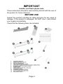
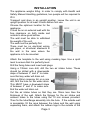
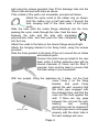
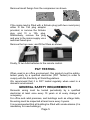
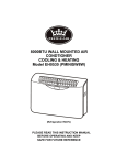
EH0554
Indoor Climate Control
3.2kW heating or cooling capacity
Air conditioning
Dehumidification
Cooling
Efficient heating via air-source heat-pump
Suitable for high- or low-wall installation
No external unit required
Page 1
IMPORTANT
Installer and Users please note:
These instructions should be read carefully and left with the user of
the product for future reference.
BEFORE USE
Inspect the product including its cable and plug for any signs of
damage. If the product is damaged, DO NOT use it, and contact
your supplier immediately.
Check that the following items are included:
Page 2
INSTALLATION
The appliance weighs 42kg. In order to comply with Health and
Safety Manual Handling guidelines, two people will be required to
lift it.
Transport and store in an upright position. Leave the unit in an
upright position for at least 3 hours before first use.
Choose the optimum location for the
appliance:
It must be on an external wall with 2m
free clearance on both inside and
outside to allow good airflow
The wall must be able to withstand
the weight of the unit.
The wall must be perfectly flat.
There must be no electrical wiring,
gas pipes, or structural steelwork in
the wall in the area where the
appliance is to be mounted.
Attach the template to the wall using masking tape. Use a spirit
level to ensure that it is perfectly level.
Drill the fixing holes and insert wall plugs.
Using a 135mm core drill, drill the two air intake holes. These
should be drilled with a downwards
slope of between 3° and 5° to make
sure that any water will drain out.
Using a 30mm masonry bit, or a core
drill, drill the hole for the water drain.
This MUST have a downward slope
of between 3° and 5° to make sure
that the water will drain out.
Cut the air intake tubes so that they are 10mm less then the
thickness of the wall. Attach the flanges for the air intake and
exhaust tubes to the tubes using the 10 mm screws provided.
Then fix the tube/flange assembly into the hole. If the outside wall
is accessible, fill the area between the tubes and the wall using
expanding foam, and attach the rubber rings to the outside of the
Page 3
wall using the screws provided, then fit the drainage tube into the
30mm hole and seal with foam as above.
If the outside of the wall is not accessible, proceed as follows.
Attach the nylon cords to the rubber ring as shown.
Fold the rubber ring in half and pass it through the
hole, keeping hold of the other ends of the nylon
cords.
Slide the tube (with the inside flange attached) into the hole,
passing the nylon cords through the tube. Seal the area
between the tube and the hole with expanding
polyurethane foam, and then push the tube completely
into the hole.
Attach the cords to the tabs on the interior flange and pull tight.
Attach the hanging bracket to the fixing holes, using the screws
provided.
Stick the foam gaskets to the back of the unit, around the air intake
and exhaust ports.
Connect the drain hose provided to the rear
drain outlet. A further extension pipe with an
internal diameter of 16mm can be fitted if
required. Care must be taken to ensure that
the drain always runs downwards.
With two people, lifting the appliance by it sides, not the front
cover, hang it on the fixing
bracket, and push firmly
against the wall, ensuring that
the drain pipe engages with
the drainage hole, and that the
main unit fits flush against the
wall. If there are any gaps
between the unit and the wall,
heating
and
cooling
performance will be impaired.If
the drain pipe does not engage
properly with the drain tube in
the wall, leakage will occur.
Page 4
Remove transit fixings from the compressor as shown.
If the mains lead is fitted with a Schuko plug (with two round pins),
either fit the 13A plug adaptor
provided, or remove the Schuko
plug and fit a 13A plug.
Alternatively, remove the plug
and wire to the mains supply via a
switched fused spur.
Remove the top cover, and fit the filters as shown.
Finally, fit two AAA batteries to the remote control.
PAT TESTING.
When used in an office environment, this product must be safetytested yearly by a qualified electrician (PAT Tested) in order to
comply with the Electricity at Work Regulations.
We recommend that it is PAT tested regularly when used in a
domestic environment.
GENERAL SAFETY REQUIREMENTS
Domestic wiring must be tested periodically by a qualified
electrician at least once every 10 years or at every change of
occupancy.
For office and retail premises, and buildings such as village halls,
the wiring must be inspected at least once every 5 years.
It is recommended that all building be fitted with smoke alarms (it is
mandatory for new buildings).
Page 5
PRODUCT SAFETY
• This appliance is not intended for use by persons (including
children) with reduced physical, sensory or mental capabilities, or
lack of experience and knowledge, unless they have been given
supervision or instruction concerning use of the appliance by a
person responsible for their safety.
• Children should be supervised to ensure that they do not play
with the appliance
• Ensure that there is at least 300mm (1') between the sides
of the appliance and any flammable materials
• Ensure that there is at least 900mm (3') from the top of the
appliance and any flammable materials.
• Do not place on soft surfaces.
• Do not cover. This symbol shown on the casing of the appliance
means that the appliance should not be covered.
• For indoor use only
• Not suitable for use in boats, caravans or similar locations.
• Do not use in bathrooms, or in wet locations.
• Do not place the mains lead beneath a carpet or rug.
• Do not use the appliance in locations where paint, petrol or other
flammable liquids are used or stored.
• Do not use unless correctly installed
• Do no insert any object into the appliance through the grilles.
This may damage the appliance or result in overheating or electric
shock.
• Do not place objects on top of the appliance.
• Do not obstruct the air intakes and exhausts
OPERATION
Plug the mains lead into a 13 Amp mains socket (unless
permanently installed)
If connecting via an extension lead, make sure that the lead is
rated at 13 Amps or more, and that it is fully unwound.
Switch the unit on at the mains socket.
Page 6
Using the remote control press the "ON/OFF" button to start the
unit. There will be a short delay (of about a minute) before the
appliance starts to operate.
Always use the ON/OFF button to start and stop the
appliance. Do not switch off at the mains socket whilst it is
running. This will reduce the life of the compressor.
"MODE" Button: Select the mode by pressing the "MODE" button.
The available modes are:
AUTO = Automatic mode: either heats or cools as required to
maintain the room temperature between 20 °C and 25 °C. The
TEMP+ and TEMP− buttons are inoperative in AUTO mode.
COOL = Cooling mode: cools if the room temperature is above
the selected temperature.Then use the TEMP+ and TEMP−
buttons to select the desired room temperature. When the
temperature reaches the desired temperature, the compressor will
stop, and the fan will continue to run.
DRY = Dehumidifying mode: removes humidity, but does not
affect room temperature. The fan operates at its lowest speed.
FAN = Fan only mode: circulates the air, but does not affect room
temperature or humidity.
HEAT = Heating mode: heats if the room is temperature is below
the selected temperature. Then use the TEMP+ and TEMP−
buttons to select the desired room temperature. When the
temperature reaches the desired temperature, the compressor will
stop, and the fan will continue to run. Heating performance
reduces if the outdoor temperature falls below 7 °C
"SPEED" Button: Set the fan speed using the fan speed control.
In all modes except dehumidifying mode. The fan speed can be
low, medium or high. The fan speed is indicated by the speed of
the segments on the windmill symbol on the LED display.
TEMP+ and TEMP− buttons:
Use the + and − buttons to select the desired room temperature.
The temperature can be set to any temperature from 16 °C to 31
°C. Selecting a lower temperature whilst heating, or a higher
temperature whilst cooling will reduce power consumption.
SLEEP MODE: The SLEEP mode is selected by the SLEEP
button (and is indicated by the "moon" icon). In SLEEP mode, the
Page 7
fan speed is set to its lowest speed.
SWING button: Press the "SWING" button to turn the oscillation of
the louvres on or off.
FAN SPEED: The fan speed can be low, medium, high or
automatic. When set to automatic, the fan speed is determined by
the amount of cooling or heating required to maintain the selected
room temperature. The fan speed is indicated by the number of
segments lit adjacent to the
symbol.
INDICATORS
The indicators on the main unit operate as follows:
The two-digit LED display shows the current room temperature:
The green LED (top left) indicates that the compressor is running
(heating or cooling is taking place)
The yellow LED (top right) indicates that the timer is operating, or if
it is flashing, indicates that the unit is defrosting.
The red LED (bottom right) indicates that the appliance is in standby.
The blue LED (bottom left) indicates that the unit is in "sleep"
mode.
The LED OFF button on the remote control controls the display of
room temperature on the front of the main unit.
USING THE TIMER
To program the time at which the unit will switch off, press TIMER
button until the
icon is displayed. Then set the number of
hours before which the appliance should switch off by pressing the
HOUR button.
To cancel the timer, press TIMER until the
icon
disappears.
To select the time at which the unit will switch on, press ON/OFF
on the remote control to switch the unit off. Then press the TIMER
button until the
icon is displayed. Then set the number of
Page 8
hours before which the appliance should switch on by pressing the
HOUR button.
To cancel the timer, press TIMER until the
icon disappears.
Setting the clock:
To set the clock, first press the CLOCK button. Then adjust the
time using the HOUR and MINUTE buttons. When the time shown
is correct, press the CLOCK button again.
OPERATING COSTS
At time of going to press, the average cost of electricity is £0.11
per unit (kilowatt-hour). The amount you are being charged will be
shown on your electricity bill.
At this cost, the EH0544 will cost £0.12 per hour to run either
cooling or heating.
To minimise the power used (and reduce operating costs):
• Make sure that the filter is kept clean.
• Make sure that the air intakes and exhausts are not obstructed.
• Keep doors and windows closed to prevent conditioned air from
escaping, and to prevent exhaust air from re-entering the room.
• Use blinds to prevent direct sunlight reaching the room.
MAINTENANCE
Before cleaning, turn the unit off using the button on the control
panel (NEVER switch off the power at the mains socket whilst the
unit is running). Wait until the unit stop and then disconnect from
the mains supply. The case may then be cleaned using a damp
cloth with a drop of washing-up liquid to remove any dust or dirt
from the case. Do no use stronger detergents or solvents as these
may damage the plastic.
Using a dry 1" (25mm) paint-brush, remove any dust from the
grilles.
Page 9
Remove the filters from the top of the unit. Clean the active carbon
Dust filter
and catalytic filters using a
vacuum cleaner.
Wash the dust filter in hand-hot
Active
carbon
water to which a drop of washingfilter
up liquid has been added.
Catalytic
Thoroughly dry before replacing
filter
in the unit.
Using the appliance with a
blocked filter will severely reduce
its efficiency, and using without
the filter may lead to a build-up of
a dust on the heat exchangers,
which may constitute a fire hazard.
If the mains lead is damaged, it must be replaced by the
manufacturer or an authorised service centre. If the mains plug
needs to be replaced, proceed as follows:
• Connect the brown wire to the
terminal labelled "L".
• Connect the blue wire to the
terminal labelled "N".
• Connect the green/yellow wire to
the terminal labelled with the earth
symbol or "E".
• Make sure that the cord-grip is
positioned correctly (over the outer sheath of the cable) and it fully
tightened.
DISPOSAL AND RECYCLING
You must not dispose of this appliance with domestic household
waste.
Most local authorities have specific collection system for
appliances and disposal is free of charge to the end-user.
When replacing an existing appliance with a similar new appliance
your retailer may take the old appliance for disposal.
This air conditioner contains R410a refrigerant gas. At the end of
its life the disposal of this product must be in accordance with local
regulations.
Page 10
FAULT-FINDING
If the appliance is not operating, proceed as follows:
Check that the mains plug is firmly in the socket, and that the
socket is switched ON.
When the unit if switched on there will be a delay of about 1 minute
before it starts to operate.
• Unit stops running:
Mains supply is disconnected or has failed
Target temperature has been reached.
Timer has been set.
Water tank is full (E6 will be displayed)
• In cooling mode, no cool air is produced:
Room temperature is lower than set temperature
The unit is defrosting (this will take a few minutes, and afterwards,
it will resume operation)
Filter is blocked
• Cooling is poor on hot days
Too much direct sunshine is heating the room
Windows or doors are open allowing hot air into the room
A lot of people in the room (each person contributes about 75W of
heating)
Electrical equipment in the room producing heat
• Remote control does not work:
Check batteries are correctly installed, and are not exhausted.
Make sure that the remote control is pointed towards the main unit
when being used.
• Water leakage
Drain hole slopes the wrong way
Drain tube not fitted correctly
• Water splashes out of the front of the appliance
Appliance has not been installed level.
FAULT CODES
If any fault codes appear on the display, contact your local service
agent.
E2: Indoor sensor failure
E4: Indoor coil sensor failure
E5: Failure of upper fan motor
Page 11
TECHNICAL SPECIFICATION
Dimensions:
Weight:
Power supply:
Cooling capacity:
Heating capacity:
Power consumption (cooling):
Power consumption (heating):
Operating current:
Air flow
Noise level:
Dehumidification capacity:
Refrigerant gas:
550×930×260 mm
42 kg
230V ~
3200 W
3200 W
1220 W
1090 W
5A
400 m3/hour
38−45 dBA
21.6 litres/day
R410a
SERVICE WARRANTY
Prem-i-Air guarantees the product free from defects in materials and
workmanship for a period of twelve months.
This Elite product is guaranteed for a further twelve months subject to the
enclosed registration card being completed and returned to the address
printed on it, or the registration form being completed on-line at
www.prem-i-air.com
Should this unit be operated under conditions other than those
recommended, at voltages other than the voltage indicated on the unit, or
any attempts made to service or modify the unit
, then the warranty
will be rendered void.
The product you buy may sometimes differ slightly from illustrations. This
warranty is in addition to, and does not affect, your statutory rights.
If you have any problems with this product, please call our Help Desk on
(0845) 459 4816.
Prem-i-Air Appliances Ltd.,
Lancots Lane, Sutton,
St. Helens, Merseyside.
WA9 3EX
website: www.prem-i-air.com
Page 12