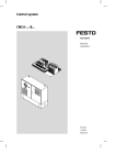
1
PSEN op2H-s-30-XXX/1
Safety light curtains with infrared beams
OPERATION MANUAL
1001421-EN-02
This document is a translation of the original document.
All rights to this documentation are reserved by Pilz GmbH &
Co. KG. Copies may be made for internal purposes.
Suggestions and comments for improving this documentation
will be gratefully received.
Pilz®, PIT®, PMI®, PNOZ®, Primo®, PSEN®, PSS®, PVIS®,
SafetyBUS p®, SafetyEYE®, SafetyNET p®, the spirit of
safety® are registered and protected trademarks of
Pilz GmbH & Co. KG in some countries.
Pilz GmbH & Co. KG
Felix-Wankel-Straße 2
73760 Ostfildern, Germany
Telephone: +49 711 3409-0
Telefax: +49 711 3409-133
E-Mail: [email protected]
www.pilz.com
PSEN op2H-s Series
Instruction Manual
INDEX
1. GENERAL INFORMATION ........................................................................................ 1
1.1. General description of the safety light curtains .................................................. 1
1.1.1. Package contents ................................................................................. 3
1.2. New features compared to the PSEN op2H Series............................................ 3
1.3. How to choose the device ................................................................................. 4
1.3.1. Resolution ............................................................................................ 4
1.3.2. Controlled height................................................................................... 5
1.3.3. Minimum installation distance ............................................................... 6
1.4. Typical applications ........................................................................................... 9
1.5. Safety information ........................................................................................... 11
2. INSTALLATION MODE............................................................................................ 12
2.1. Precautions to be observed for the choice and installation of the device......... 12
2.2. General information on device positioning ....................................................... 13
2.2.1. Minimum installation distance ............................................................. 14
2.2.2. Minimum distance from reflecting surfaces ......................................... 15
2.2.3. Emitter and receiver orientation .......................................................... 17
2.2.4. Installation of several adjacent safety light curtains ............................. 18
2.2.5. Use of deviating mirrors ...................................................................... 19
2.2.6. Controls after first installation .............................................................. 20
3. MECHANICAL MOUNTING ..................................................................................... 22
4. ELECTRICAL CONNECTIONS ................................................................................ 25
4.1. Notes on connections ...................................................................................... 26
4.2. Earth connection ............................................................................................. 29
5. ALIGNMENT PROCEDURE..................................................................................... 30
5.1. Correct alignment procedure ........................................................................... 32
6. FUNCTIONING MODE ............................................................................................. 33
6.1. Reset mode..................................................................................................... 33
6.2. Test function ................................................................................................... 33
6.3. Reset function ................................................................................................. 34
7. DIAGNOSTIC FUNCTIONS ..................................................................................... 35
7.1. User interface.................................................................................................. 35
7.2. Diagnostic messages ...................................................................................... 36
8. PERIODICAL CHECKS ........................................................................................... 38
8.1. General information and useful data ................................................................ 39
9. DEVICE MAINTENANCE ......................................................................................... 40
9.1. Product disposal.............................................................................................. 40
10. TECHNICAL DATA .................................................................................................. 41
11. LIST OF AVAILABLE MODELS .............................................................................. 42
12. OVERALL DIMENSIONS ......................................................................................... 43
13. OUTFIT .................................................................................................................... 44
14. ACCESSORIES ....................................................................................................... 45
14.1 Angled fixing bracket mounting ....................................................................... 46
15. GLOSSARY ............................................................................................................. 50
Instruction Manual
PSEN op2H-s Series
1. GENERAL INFORMATION
1.1. General description of the safety light curtains
The safety light curtains of the PSEN op2H-s series are
optoelectronic multibeam devices that are used to protect working
areas that, in presence of machines, robots, and automatic systems
in general, can become dangerous for operators that can get in
touch, even accidentally, with moving parts.
The light curtains of the PSEN op2H-s series are Type 2 intrinsic
safety systems used as accident-prevention protection devices and
are manufactured in accordance with the international Standards in
force for safety, in particular:
CEI IEC 61496-1: 2004
Safety of machinery: electrosensitive protective equipment. Part
1: General prescriptions and tests.
CEI IEC 61496-2: 2006
Safety of machinery: electrosensitive protective equipment Particular requirements for
equipment using active
optoelectronic protective devices.
The device, consisting of one emitter and one receiver housed inside
strong aluminium profiles, generates infrared beams that detect any
opaque object positioned within the light curtain detection field. The
emitter and the receiver are equipped with the command and control
functions. The connections are made through a M12 connector
located in the lower side of the profile. The synchronisation between
the emitter and the receiver takes place optically, i.e. no electrical
connection between the two units is required. The microprocessor
guarantees the check and the management of the beams that are
sent and received through the units. The microprocessor – through
some LEDs – informs the operator about the general conditions of
the safety light curtain (see section 7 “Diagnostic functions”).
1
PSEN op2H-s Series
Instruction Manual
The device consists in 2 units that, according to the model, are
composed by one or several emitting and receiving modules.
The receiver checks the control operations and safety actions.
During installation, two yellow LEDs facilitate the alignment of both
units (see section 5 “Alignment procedure”).
As soon as an object, a limb or the operator’s body accidentally
interrupts one or some of the infrared beams sent by the emitter, the
receiver immediately opens the OSSD outputs and blocks the MPCE
machine (if correctly connected to the OSSD).
Some parts or sections of this manual containing important
information for the operator are preceded by a note:
Notes and detailed descriptions about particular characteristics of the
safety devices in order to better explain their functioning.
Special instructions regarding the installation process.
The information provided in the paragraphs following this symbol is
very important for safety and may prevent accidents.
Always read this information accurately and carefully follow the
advice to the letter.
This manual contains all the information necessary for the selection
and operation of the safety devices.
However, specialised knowledge not included in this technical
description is required for the planning and implementation of a
safety light curtain on a power-driven machine. As the required
knowledge may not be completely included in this manual, we
suggest the customer to contact Pilz Technical Service for any
necessary information relative to the functioning of the PSEN op2H-s
light curtains and the safety rules that regulate the correct installation
(see section 8 “Periodical checks ”).
2
Instruction Manual
PSEN op2H-s Series
1.1.1. Package contents
Package contains the following objects:
• Receiver (RX)
• Emitter (TX)
• Quick Guide for first installation
• CD with user manual and other documents
• Checklist and periodical maintenance schedule
• 4 angled fixing brackets and specific fasteners
• 2 angled fixing brackets for models with heights included between
1200 and 1800 mm
1.2. New features compared to the PSEN op2H Series
The PSEN op2H-s safety light curtains, compared
PSEN op2H-s series, present the following new features:
to
the
• Increased operating distance
• Range enlargement with 150 to 1800 mm controlled heights
• Reduced response times
• New fastening system with rotating brackets
• New mechanical profile compatible with PSEN op2H-s accessories
• Different positioning of synchronisation optics (the first one from the
reference line)
• Different mechanical mounting
3
PSEN op2H-s Series
Instruction Manual
1.3. How to choose the device
There are at least three different main characteristics that should be
considered when choosing a safety light curtain, after having
evaluated the risk assessment:
1.3.1. Resolution
The resolution of the device is the minimum dimension that an
opaque object must have in order to obscure at least one of the
beams that constitute the sensitive area.
The resolution strictly depends on the part of the body to be
protected.
R = 30 mm
hand protection
Type 2
As shown in Fig.1, the resolution only depends on the geometrical
characteristics of the lenses, diameter and distance between centres,
and is independent from any environmental and operating conditions
of the safety light curtain.
Fig. 1
The resolution value is obtained applying the following formula:
R=I+d
where:
I
d
= Distance between two adjacent optics
= Lens diameter
4
Instruction Manual
PSEN op2H-s Series
1.3.2. Controlled height
The controlled height is the height protected by the safety light
curtain ( Hp )
Fig. 2
The PSEN op2H-s controlled height is delimited by the yellow line
pad-printed on the front glass and by the dimensions listed in the
table:
Model
Hp
Controlled
height Hp
(mm)
PSEN op2H-s-30-015/1
150
PSEN op2H-s-30-030/1
300
PSEN op2H-s-30-045/1
450
PSEN op2H-s-30-060/1
600
PSEN op2H-s-30-075/1
750
PSEN op2H-s-30-090/1
900
PSEN op2H-s-30-105/1
1050
PSEN op2H-s-30-120/1
1200
PSEN op2H-s-30-135/1
1350
PSEN op2H-s-30-150/1
1500
PSEN op2H-s-30-165/1
1650
PSEN op2H-s-30-180/1
1800
Reference
5
PSEN op2H-s Series
Instruction Manual
1.3.3. Minimum installation distance
The safety device must be positioned at a specific safety distance
(Fig. 3). This distance must ensure that the dangerous area cannot
be reached before the dangerous motion of the machine has been
stopped by the AOPD.
The safety distance depends on 4 factors, according to the EN-999
Standard:
• Response time of the AOPD (the time between the effective beam
interruption and the opening of the OSSD contacts).
• Machine stopping time (the time between the effective opening of
the contacts of the AOPD and the real stop of the dangerous
motion of the machine).
• AOPD resolution.
• Approaching speed of the object to be detected.
Fig. 3
The following formula is used for the calculation of the safety
distance:
S = K (t1 + t2) + C
where:
S = Minimum safety distance in mm.
K = Speed of the object, limb or body approaching the
dangerous area in mm/sec.
t1 = Response time of the AOPD in seconds (see section 9
“Technical data”)
t2 = Machine stopping time in seconds.
d = Resolution of the system.
C = Additional distance based on the possibility to insert the body or
one of body parts inside the dangerous area before the protective
device trips.
C = 8 (d -14) for devices with resolution ≤ 40mm
C = 850 mm for devices with resolution > 40mm.
6
Instruction Manual
PSEN op2H-s Series
NOTE: K value is:
2000 mm/s if the calculated value of S is ≤ 500 mm
1600 mm/s if the calculated value of S is > 500 mm
When devices with >40 mm resolution are used, the height of the top
beam has to be ≥ 900 mm (H2) from machine supporting base while
the height of the bottom beam has to be ≤ 300 mm (H1).
If the safety light curtain must be mounted in a horizontal position
(Fig.4), the distance between the dangerous area and the most
distant optical beam must be equal to the value calculated using the
following formula:
S = 1600 mm/s (t1 + t2) + 1200 – 0.4 H
where:
S = Minimum safety distance in mm.
t1 = Response time of the AOPD in seconds
(see section 9 “Technical data”)
t2 = Machine stopping time in seconds.
H = Beam height from ground; this height must always be less than
1,000 mm.
Fig. 4
7
PSEN op2H-s Series
Instruction Manual
Practical examples:
Let's suppose to have a light curtain with height = 600 mm
1) To calculate the distance of the device from the AOPD, in a vertical
position, the following formula is used:
S = K*T + C
where:
T = t1 + t2
t1 = AOPD response time + PNOZsigma relay release time (max 80 ms)
t2 = Machine total stopping time.
C = 8 * (d – 14) for devices with resolution <= 40 mm
C = 850 for devices with resolution > 40 mm
d = Resolution of the system.
In all cases, if K = 2000mm/sec then S will be > 500 mm.
Distance will have then to be recalculated using K = 1600 mm/sec.
T
C
S
PSEN op2H-s-30-060/1
0.398 sec
128 mm
764.8 mm
2) To calculate the distance of the device from the AOPD, in a
horizontal position, the following formula is used:
S = 1600 * T + 1200 – 0.4 * H
where:
H = Beam min. height from ground 15 * (d – 50)
D = resolution
t
H
S
PSEN op2H-s-30-060/1
0.3 Sek.
0 mm
1828.8 mm
WARNING: the reference standard is EN 999 “Machine safety - the
positioning of the protective device based on the approaching speed
of the human body”.
This information is just an indication and a kind of summary.
For safety distance correct calculation, it is compulsory to refer to the
whole EN 999 standard.
8
Instruction Manual
PSEN op2H-s Series
1.4. Typical applications
The safety light curtains of the PSEN op2H-s series are used in all
automation fields where the control and protection of the access to
dangerous areas are necessary.
In particular, they are used to stop the moving of mechanical parts in:
- Automatic machines;
- Machines for packaging, material handling, storing;
- Weaving machines, wood working machines, ceramic working
machines;
- Automatic and semiautomatic assembly lines;
- Automatic warehouses.
In food industry applications, Pilz Technical Service has to
verify the compatibility of the material of the safety light curtain
housing with any chemical agents used in the production
process.
Example 1: Cooling and conditioning systems
Cooling
and
conditioning
systems, as well as automotive
equipment and components are
checked inside a machine, to
detect possible leaks by a
helium mass spectrometer. The
point where these parts are
positioned inside the measuring
chamber requires a Type 2
protection ensuring a certain
space saving and an easy access to the protected area.
Solution: the PSEN op2H-s safety light curtain series represents the
ideal solution if the safety requirements and the application are
considered. When even just one of the light curtain beams is
interrupted, the test machine is immediately stopped.
Advantages: the PSEN op2H-s light curtain meets the customer's
needs when easy access is necessary in presence of machine stops.
Easy installation, configuration and use are other advantages.
9
PSEN op2H-s Series
Instruction Manual
Example 2: Automatic warehouses
Operator protection in automatic warehouses.
Solution: the PSEN op2H-s safety light curtain series represents the
ideal solution if the safety requirements and the application are
considered. When even just one of the light curtain beams is
interrupted, the carousel is immediately stopped.
Advantages: the PSEN op2H-s light curtain meets the customer's
needs when easy access is necessary in presence of machine stops.
Easy installation, configuration and use are other advantages.
10
Instruction Manual
PSEN op2H-s Series
1.5. Safety information
For a correct and safe use of the safety light curtains of the PSEN
op2H-s series, the following points must be observed:
• The stopping system of the machine must be electrically controlled.
• This control system must be able to stop the dangerous movement
of the machine within the total machine stopping time T as per par.
1.1.3, and during all working cycle phases.
• Mounting and connection of the safety light curtain must be carried
out only by qualified personnel, according to the indications
included in the special sections (refer to sections 2; 3; 4; 5) and in
the applicable Standards.
• The safety light curtain must be securely installed in a particular
position so that access to the dangerous zone is not possible
without the interruption of the beams (see section 2 “Installation
mode”).
• The personnel operating in the dangerous area must be well trained
and must have adequate knowledge of all the operating procedures
of the safety light curtain.
• The TEST button must be located outside the protected area
because the operator must check the protected area during all Test
and Reset operations.
Please carefully read the instructions for the correct functioning
before powering the light curtain.
11
PSEN op2H-s Series
Instruction Manual
2. INSTALLATION MODE
2.1. Precautions to be observed for the choice and installation of the
device
Make sure that the protection level assured by the PSEN op2H-s
device (Type 2) is compatible with the real danger level of the
machine to be controlled, according to EN 954-1 and EN 13849.
• The outputs (OSSD) of the AOPD must be used as machine
stopping devices and not as command devices. The machine must
have its own START command.
• The dimension of the smallest object to be detected must be larger
than the resolution level of the device.
• The AOPD must be installed in a room complying with the technical
characteristics indicated in section 10 “Technical data”.
• Do not place the device near intense and/or flashing light sources
and, in particular, close to receiving unit front surface.
• The presence of intense electromagnetic disturbances could affect
device correct operation. This condition shall be carefully assessed
by seeking the advice of Pilz Technical service.
• The operating distance of the device can be reduced in presence of
smog, fog or airborne dust.
• A sudden change in environment temperature, with very low
minimum peaks, can generate a small condensation layer on the
lenses and so jeopardise functioning.
12
Instruction Manual
PSEN op2H-s Series
2.2. General information on device positioning
The safety light curtain should be carefully positioned, in order to
reach a very high protection standard. Access to the dangerous area
must only be possible by passing through the protecting safety light
beams.
Fig.5a shows some examples of possible access to the machine from
the top and the bottom sides. These situations may be very
dangerous and so the installation of the safety light curtain at
sufficient height in order to completely cover the access to the
dangerous area (Fig.5b) becomes necessary.
NO
Fig.5a
YES
Fig.5b
Under standard operating conditions, machine starting must not be
possible while operators are inside the dangerous area.
13
PSEN op2H-s Series
Instruction Manual
When the installation of the safety light curtain very near to the
dangerous area is not possible, a second light curtain must be
mounted in a horizontal position in order to prevent any lateral
access (as shown in Fig.6b).
If the operator is able to enter the dangerous area, an additional
mechanical protection must be mounted to prevent the access.
NO
Fig.6a
YES
Fig.6b
2.2.1. Minimum installation distance
Refer to par.1.3.3. “Minimum installation distance”
14
Instruction Manual
PSEN op2H-s Series
2.2.2. Minimum distance from reflecting surfaces
Reflecting surfaces placed near the light beams of the safety device
(over, under or laterally) can cause passive reflections. These
reflections can compromise the recognition of an object inside the
controlled area.
However, if the RX receiver detects a secondary beam (reflected by
the side-reflecting surface) the object might not be detected, even if
the object interrupts the main beam.
Fig. 7
15
PSEN op2H-s Series
Instruction Manual
It is thus important to position the safety light curtain according to the
minimum distance from reflecting surfaces.
The minimum distance depends on:
• Operating distance between emitter (TX) and receiver (RX);
• Real opening angle of AOPD (EAA); in particular:
for AOPD type 2
EAA = 10° (α = 5°)
Distance from reflecting surface (Dsr)
Diagram of Fig. 8 shows the min. distance from the reflecting surface
(Dsr), based on the operating distance:
AOPD
Type 2
Operating distance
Fig. 8
The formula to get Dsr is the following:
Dsr (m) = 0.27
Dsr (m) = 0,5 operating distance (m) x tg 2α
for oper. distances < 3 m
for oper. distances ≥ 3 m
16
Instruction Manual
PSEN op2H-s Series
2.2.3. Emitter and receiver orientation
The two units shall be installed parallel to each other, with the beams
orthogonal respect to the emitting and receiving directions, with the
connectors positioned in the same manner.
The configurations shown in Fig. 9 must be avoided:
NO
NO
Fig.9
17
PSEN op2H-s Series
Instruction Manual
2.2.4. Installation of several adjacent safety light curtains
When several safety devices must be installed in adjacent areas,
interferences between the emitter of one device and the receiver of
the other must be avoided.
Fig.10 provides an example of possible interferences between
different devices and two pertinent solutions.
NO
YES
RX
TX
YES
Fig.10
18
Instruction Manual
PSEN op2H-s Series
2.2.5. Use of deviating mirrors
The control of any dangerous area, with several but adjacent access
sides, is possible using only one safety device and well-positioned
deviating mirrors.
Fig.11 shows a possible solution to control three different access
sides, using two mirrors placed at 45° with respect to the beams.
Fig. 11
The operator must respect the following precautions when using the
deviating mirrors:
• The alignment of the emitter and the receiver can be a very critical
operation when deviating mirrors are used. Even a very small mirror
displacement is enough to lose alignment. The use of the Pilz laser
pointer accessory is recommended under these conditions.
• The minimum safety distance (S) must be respected for each single
section of the beams.
• The effective operating range decreases by about 15% by using
only one deviating mirror, the percentage further decreases by
using 2 or more mirrors (for more details refer to the technical
specifications of the mirrors used).
The following table shows the operating distances relating to the
number of mirrors used.
number of mirrors
1
2
3
operating distance
16.5 m
13.7 m
11.6 m
• Do not use more than three mirrors for each device.
• The presence of dust or dirt on the reflecting surface of the mirror
causes a drastic reduction in the range.
19
PSEN op2H-s Series
Instruction Manual
2.2.6. Controls after first installation
The control operations to carry-out after the first installation and
before machine start-up are listed hereinafter. The controls must be
carried-out by qualified personnel, either directly or under the strict
supervision of the person in charge of machinery Safety.
Verify that:
AOPD remains blocked (
) intercepting the beams along the
protected area using the specific test piece, following the Fig.12
scheme.
TP30 for light curtains with 30 mm resolution: PSEN op2H-s-30
Fig. 12
• AOPD has to be correctly aligned, press slightly on the product side
in both directions the red LED must not turn on
.
• The activation of the TEST function causes the opening of the
on and controlled machine stop).
OSSD outputs (red LED
• The response time at machine STOP, including the AOPD and
machine response times, must be included in the limits defined in
the calculation of the safety distance (refer to section 2 “Installation
modes”).
• The safety distance between the dangerous parts and AOPD must
comply with the requirements indicated in section 2 “Installation
modes”.
20
Instruction Manual
PSEN op2H-s Series
• A person must not access or remain between AOPD and the
dangerous parts of the machine.
• Access to the dangerous areas of the machine must not be
possible from any unprotected area.
• AOPD must not be disturbed by external light sources, ensuring
that it remains in Normal operating function for at least 10-15
minutes and placing the specific test piece in the protected area in
the SAFE condition for the same period.
• Verify the correspondence of all the accessory functions, activating
them in the different operating conditions.
21
PSEN op2H-s Series
Instruction Manual
3. MECHANICAL MOUNTING
The emitting (TX) and receiving (RX) units must be installed with the
relevant sensitive surfaces facing each other. The connectors must be
positioned on the same side and the distance must be included within
the operating range of the model used (see section 10 “Technical
data”).
The two units must be positioned the most aligned and parallel
possible.
The next step is the fine alignment, as shown in section 5 “Alignment
Procedure”.
Two types of brackets can be used to fix the two units:
Rotating brackets
Rotating fixing brackets are supplied with all models (Fig.13).
They can be used separately from or together with the angled fixing
brackets.
Fig. 13
22
Instruction Manual
PSEN op2H-s Series
Angled fixing brackets
Angled fixing brackets (Fig.14), are supplied with all models.
Fig. 14
In case of applications with particularly strong vibrations, vibration
dampers, together with mounting brackets, are recommended to
reduce the impact of the vibrations.
Fig. 15
The recommended mounting positions according to the light curtain
length are shown in Fig.15 and in the following table.
23
PSEN op2H-s Series
Instruction Manual
L (mm)
A (mm)
B (mm)
C (mm)
PSEN op2H-s-30-015/1
216.3
108
54
-
PSEN op2H-s-30-030/1
366.2
216
75
-
PSEN op2H-s-30-045/1
516.3
316
100
-
PSEN op2H-s-30-060/1
666.2
366
150
-
PSEN op2H-s-30-075/1
816.3
466
175
-
PSEN op2H-s-30-090/1
966.2
566
200
-
PSEN op2H-s-30-105/1
1116.2
666
225
-
PSEN op2H-s-30-120/1
1266.3
966
150
483
PSEN op2H-s-30-135/1
1416.2
1066
175
533
PSEN op2H-s-30-150/1
1566.3
1166
200
583
PSEN op2H-s-30-165/1
1716.3
1266
225
633
PSEN op2H-s-30-180/1
1866.3
1366
250
683
MODELS
kk = Resolution (30mm – 50 mm – 90 mm)
24
Instruction Manual
PSEN op2H-s Series
4. ELECTRICAL CONNECTIONS
All electrical connections to the emitting and receiving units are made
through a male M12 connector, located on the lower part of the two
units. For receiver a M12 5-pole connector is used, while for emitter a
M12 4-pole connector is used.
RECEIVER (RX) *):
OSSD1
2
+24 VDC
1
TEST/RESET
5
4
3
OSSD2
0V
1
2
3
4
5
=
=
=
=
=
brown
white
blue
black
grey
=
=
=
=
=
+24 VDC
OSSD 1
0V
OSSD 2
TEST/RESET
EMITTER (TX) *):
NOT USED
0V
1
2
3
4
=
=
=
=
brown
white
blue
black
=
=
=
=
2
1
3
4
+24 VDC
NOT USED
+24 VDC
NOT USED
0V
NOT USED
*) plugs an pinning compatible to PSEN op4F/H series
25
PSEN op2H-s Series
Instruction Manual
4.1. Notes on connections
For the correct functioning of the PSEN op2H-s safety light curtains,
the following precautions regarding the electrical connections have to
be respected:
• Do not place connection cables in contact with or near high-voltage
cables and/or cable undergoing high current variations (e.g. motor
power supplies, inverters, etc.);
• Do not connect in the same multi-pole cable the OSSD wires of
different light curtains;
• The TEST/RESET wire must be connected through a N.O. button to
the supply voltage of the AOPD.
The TEST/RESET button must be located in such a way that the
operator can check the protected area during any Test and Reset
operation. (see section 6 “Functioning mode”).
• The device is protected internally against overvoltage and
overcurrent. The use of other external components is not
recommended.
26
Instruction Manual
PSEN op2H-s Series
You may use for example a safety relay of the PNOZsigma (PNOZ
s4, PNOZ s5) range as an evaluation device. The wiring is described
in the operating manual of the PNOZsigma unit.
• Do not use varistors, RC circuits or LEDs in parallel at relay inputs
or in series at OSSD outputs.
• The OSSD1 and OSSD2 safety contacts cannot be connected in
series or in parallel, but can be used separately (Fig.16).
If one of these configurations is erroneously used, the device enters
into the output failure condition (see section 7 “Diagnostic
functions”).
27
PSEN op2H-s Series
Instruction Manual
• Connect both OSSDs to the activating device. Failure to connect an
OSSD to the activating device jeopardises the system safety
degree that the light curtain has to control
YES
NO
Fig. 16
NO
Fig. 18
Fig. 17
NO
Fig. 19
28
Instruction Manual
PSEN op2H-s Series
4.2. Earth connection
PSEN op2H-s safety light curtain units are preset for easy ground
connection. A special compartment, positioned onto caps and
marked with the special symbol shown in Figure 20, allows
connection with ground cable by means of an additional screw
coming with the equipment.
Fig. 20
Ground connection configuration is the most common and
guarantees the best immunity against electromagnetic disturbances.
PSEN op2H-s can function even without ground connection.
This condition has to be carefully evaluated according to the EMC
disturbance immunity and necessary insulation class considering the
plant or entire system where the light curtain is installed.
29
PSEN op2H-s Series
Instruction Manual
5. ALIGNMENT PROCEDURE
The alignment between the emitting and the receiving units is
necessary to obtain the correct functioning of the light curtain.
A good alignment prevents outputs instability caused by dust or
vibrations.
The alignment is perfect if the optical axes of the first and the last
emitting unit’s beams coincide with the optical axes of the
corresponding elements of the receiving unit.
The beam used to synchronise the two units is the first after the
connector. SYNC is the optics connected with this beam and LAST is
the optics connected to the last beam after the SYNC unit.
last optics (LAST)
first optics = synchronisation optics (SYNC)
Fig.21
Signals are clearly identified through symbols allowing immediate
reading, independent of bars directions. A short description of the
signalling LEDs is necessary to avoid misunderstandings.
Receiver
Emitter
NORMAL
OP.
LAST
SAFE(BREAK)
SYNC
NORMAL
OP.
ON
Fig. 22
30
Instruction Manual
PSEN op2H-s Series
The standard installation described hereinafter is the one shown in Fig.
22, i.e. with the bar assembled with the connectors pointing down.
LAST,
SYNC) on PSEN op2H-s receiver,
Two yellow LEDs (
facilitates the alignment procedure. During standard operation, the
LEDs indicate the safety light curtain status, as shown in the table.
FUNCTIONING STATUS
LED colour
Symbol
Normal
Status
NORMAL OP.
Yellow
OFF
ON
OFF
OFF
Yellow
OFF
ON
ON
OFF
Red
OFF
ON
ON
ON
Green
ON
OFF
OFF
OFF
- Standard
condition:
- Not
interrupted
beams
31
Stop
Status
SAFE(BREAK)
- Units not
- Bottom side
aligned
not aligned
- Top side
not aligned - Lowest beam
interrupted
- Highest
beam
interrupted
Units aligned,
but at least
one of beams
(the highest
and lowest
excluded) is
interrupted
PSEN op2H-s Series
Instruction Manual
5.1. Correct alignment procedure
The light curtain alignment can be effected only after having completed the
mechanical installation and the electrical connections. The following
procedure has to be followed:
• Check the green LED () and the yellow LED (
the emitter is running correctly;
) on the TX unit. If ON,
• Verify that the sensitive area from the safety light curtain is free;
• Verify that one of the following conditions is present on the RX unit:
STANDARD CONDITION - NORMAL OP.
• Green LED (
) ON and red LED (
( , ) are OFF. Units are aligned.
) OFF. Both yellow LEDs
STOP CONDITION - SAFE (BREAK)
• Green LED (
) OFF and red LED (
• The status of both yellow LEDs (
aligned.
,
) ON.
) does not matter. Units are not
• Continue with the following steps to pass from condition 2 to condition 1:
A Keep the receiver in a steady position and set the emitter until the
yellow LED (
SYNC) is OFF. This condition shows the effective
alignment of the first synchronisation beam.
B Rotate the emitter, pivoting on the lower optics axis, until the yellow
LED (
LAST) is OFF. Under these conditions, the SAFE LED shall
turn ON.
is steady ON.
NOTE: Ensure that the green LED
is steady through some micro
C Delimit the area in which the LED
adjustments - for the first and then for the second unit - then place
both units in the centre of this area.
• Fix the two units firmly using brackets.
•
Verify that the green LED on the RX unit is ON (
) and beams
are not interrupted, then verify that the red LED turns ON if even one
single beam is interrupted (condition where an object has been detected).
• This verification shall be made with the special cylindrical “Test Piece”
having a size suitable to the resolution of the device used.
NOTE: Passing the Test Piece along the whole sensitive area and at any
) shall be always ON
distance from the two units, the red LED (
and never change status.
A daily test is recommended.
32
Instruction Manual
PSEN op2H-s Series
6. FUNCTIONING MODE
6.1. Reset mode
The interruption of a beam due to an opaque object causes the
opening of OSSD outputs and the stop of the safety light curtain
SAFE (BREAK) condition
.
The AOPD will automatically restart its standard operation (NORMAL
OP. condition
) as soon as the object is removed.
WARNING: Carefully assess risk conditions and reset modes.
In applications protecting access to dangerous areas, the automatic
reset mode is potentially unsafe if it allows the operator to pass
completely beyond the sensitive area (see Fig. 6b). In this case, the
reset, using for example the manual reset of the Pilz safety relay,
might be necessary.
6.2. Test function
The TEST function can be activated by keeping a normally open
external contact (TEST push-button), closed for at least 0.5 seconds.
The TEST signal is active high.
33
PSEN op2H-s Series
Instruction Manual
6.3. Reset function
The RX light curtain has a RESET function which is activated after an
internal error. The reset can be made only in case of optical error or
OSSD error (See sect. 7 “Diagnostic Functions”)
The RESET function can be activated by keeping a normally open
external contact (RESET/RESTART push-button), closed for at least
5 seconds.
The RESET signal is active high.
34
Instruction Manual
PSEN op2H-s Series
7. DIAGNOSTIC FUNCTIONS
7.1. User interface
The operator can visualise the operating condition of the light
curtains through the four LEDs positioned on the receiver unit and
two LEDs on the emitter unit.
Fig.23 shows all signalling LEDs modes: OFF, ON and BLINKING.
LED OFF
LED BLINKING
LED ON
Fig. 23
35
PSEN op2H-s Series
Instruction Manual
7.2. Diagnostic messages
The operator is able to check the main causes of the system stop
and failure, using the same LEDs used for visualising the functions.
For Receiver:
Function
Normal operation
Function
Error status
Status
Meaning
TEST
(red ON)
Light curtain being tested, the
OSSD status shall be OFF
Emission
(OSSD ON)
(green ON)
Interruption
(OSSD OFF)
(red ON)
LED
Light curtain working and in
standard operating conditions
Light curtain working and in
safety block conditions.
Type
Check and repair
OSSD error
(yellow and red
BLINKING)
Check OSSD connections;
make sure that they are not in
contact with one another or
with the supply cables, then
Reset. If the failure continues
contact Pilz
Internal error
(red ON, yellow
BLINKING)
Switch OFF and switch ON
the supply circuit; if the failure
continues contact Pilz
Optical error
(red ON, yellow
BLINKING)
Reset. If the failure continues
contact Pilz
No power
supply
(LEDs OFF)
Check connections and input
voltage correct value.
If the failure continues contact
Pilz
LED
36
Instruction Manual
PSEN op2H-s Series
For Emitter:
Function
Status
Meaning
Test
(green ON)
Light curtain being tested, the
OSSD status must be OFF
Emission (green
ON yellow ON)
Light curtain working in
normal operating conditions
Type
Check and repair
LED
Normal operation
Function
Error status
Internal error
(green ON
yellow
BLINKING)
Optic error
(green ON
yellow
BLINKING)
No power supply
(LEDs OFF)
37
Switch OFF and switch ON
the power supply circuit. If the
failure continues contact Pilz
Switch OFF and switch ON
the power supply circuit. If the
failure continues contact Pilz
Check connections and input
voltage value. If the failure
continues contact Pilz
LED
PSEN op2H-s Series
Instruction Manual
8. PERIODICAL CHECKS
The following is a list of recommended check and maintenance
operations that should be periodically carried out by qualified
personnel.
Check that:
• The AOPD stays locked (
) during beam interruption along the
entire protected area, using the suitable “Test Piece”. (*)
• The AOPD is correctly aligned: by slightly pressing product side, in
both directions, the red LED shall not come ON
.
• Enabling the TEST function, the OSSD outputs should open (the
red LED
is ON and the controlled machine stops).
• The response time upon machine STOP (including response time
of the AOPD and of the machine) is within the limits defined for the
calculation of the safety distance (see section 2 “Installation
mode”).
• The safety distance between the dangerous areas and the AOPD
are in accordance with the instructions included in section 2
“Installation mode”.
• Access of a person between AOPD and machine dangerous parts
is not possible nor is it possible for him/her to stay there.
• Access to the dangerous area of the machine from any unprotected
area is not possible.
• The AOPD and the external electrical connections are not
damaged.
The frequency of checks depends on the particular application and
on the operating conditions of the safety light curtain.
(*) according to the Fig.12 scheme
Verify that:
AOPD remains blocked (
) intercepting the beams along the
protected area using the specific test piece, following the Fig.12
scheme.
TP30 for light curtains with 30 mm resolution: PSEN op2H-s-30
38
Instruction Manual
PSEN op2H-s Series
8.1. General information and useful data
Safety MUST be a part of our conscience.
The safety devices fulfil their safety function only if they are correctly
installed, in accordance with the Standards in force.
If you are not certain to have the expertise necessary to install the
device in the correct way, Pilz Customer Service is at your disposal
to carry out the installation.
The device uses fuses that are not self-resetting. Consequently, in
presence of short-circuits causing the cut-off of these fuses, both
units shall be sent to Pilz service department.
A power failure caused by interferences may cause the temporary
opening of the outputs, but the safe functioning of the light curtain will
not be compromised.
39
PSEN op2H-s Series
Instruction Manual
9. DEVICE MAINTENANCE
PSEN op2H-s safety light curtains do not require special maintenance
operations.
To avoid the reduction of the operative distance, optics protective front
surfaces shall be cleaned at regular intervals.
To this end, use soft cotton cloths damped in water; do not apply too
much pressure onto the surface so as not to make it dull.
Please do not use on plastic surfaces or light curtain painted surfaces:
• alcohol or solvents
• wool or synthetic cloths
• paper or other abrasive materials
9.1. Product disposal
Under current Italian and European laws, Pilz is not obliged to take
care of product disposal at the end of its life.
Pilz recommends to dispose of the product in compliance with local
laws or contact authorised waste collection centres.
40
Instruction Manual
PSEN op2H-s Series
10. TECHNICAL DATA
The product technical specifications are given below.
ELECTRICAL DATA
Power supply (Vdd):
Unit current draw (TX):
Unit current draw (RX):
Outputs:
Short-circuit protection:
Output current:
Output voltage – status ON:
Output voltage – status OFF:
Capacitive load
Response times:
Protected height:
Safety category:
Auxiliary functions:
Electrical protection:
Connections:
Cables length (for power supply):
OPTICAL DATA
24 Vdc ± 20%
2 W max
3.5 W max (without load)
2 PNP
1.4 A max
0.5 A max / each output
Vdd –1 V min
0.2 V max
2.2 uF @ 24Vdc max
See table below
150..1800mm
Type 2
Reset / Test
Class I / Class III (see sect.4.2)
M12-4 poles for emitter
M12-5 poles for receiver
50 m. max
Infrared, LED (950 nm)
Emitting light ( λ ) :
Resolution:
30 mm
Operating distance:
0.2…19 m
Ambient light rejection:
IEC-61496-2
MECHANICAL AND ENVIRONMENTAL DATA
Operating temperature:
-10…+ 55 °C
Storage temperature:
-25…+ 70 °C
Humidity:
15…95 % (no condensation)
Mechanical protection:
IP 65 (EN 60529)
Vibrations:
Width 0.35 mm, Frequency 10 … 55 Hz
20 sweep per axis, 1octave/min
(EN 60068-2-6)
Shock resistance:
16 ms (10 G) 1,000 shocks per axis
(EN 60068-2-29)
Housing material:
Painted aluminium (yellow RAL 1003)
Front side material:
PMMA
Caps material:
PC MAKROLON
Weight (single unit):
1.3 kg / linear metre
41
PSEN op2H-s Series
Instruction Manual
11. LIST OF AVAILABLE MODELS
MODEL
Protected
Height
(mm)
No.
Beams
PSEN op2H-s-30-015/1
150
PSEN op2H-s-30-030/1
Response
time
(msec)
Resolution
8
8
30
300
16
9
30
PSEN op2H-s-30-045/1
450
24
11
30
PSEN op2H-s-30-060/1
600
32
12
30
PSEN op2H-s-30-075/1
750
40
14
30
PSEN op2H-s-30-090/1
900
48
15
30
PSEN op2H-s-30-105/1
1050
56
17
30
PSEN op2H-s-30-120/1
1200
64
18
30
PSEN op2H-s-30-135/1
1350
72
20
30
PSEN op2H-s-30-150/1
1500
80
21
30
PSEN op2H-s-30-165/1
1650
88
23
30
PSEN op2H-s-30-180/1
1800
96
24
30
(mm)
42
Instruction Manual
PSEN op2H-s Series
M2 n°3
x2
36.9
Ø16
Ø16
12.5
12. OVERALL DIMENSIONS
M12
32.3
38
14
L2
50.5
L1
MODEL
L1
L2
PSEN op2H-s-30-015/1
233.3
153.3
PSEN op2H-s-30-030/1
383.2
303.2
PSEN op2H-s-30-045/1
533.2
453.3
PSEN op2H-s-30-060/1
683.2
603.2
PSEN op2H-s-30-075/1
833.2
753.3
PSEN op2H-s-30-090/1
983.2
903.2
PSEN op2H-s-30-105/1
1133.2
1053.2
PSEN op2H-s-30-120/1
1283.3
1203.3
PSEN op2H-s-30-135/1
1433.2
1353.2
PSEN op2H-s-30-150/1
1583.3
1503.3
PSEN op2H-s-30-165/1
1733.3
1653.3
PSEN op2H-s-30-180/1
1883.3
1803.3
kk =
43
Resolution (30mm – 50 mm – 90 mm)
PSEN op2H-s Series
Instruction Manual
13. OUTFIT
Rotating fixing bracket
MODEL
PSEN op bracket turnable (kit) (630772)
DESCRIPTION
Rotating fixing bracket (kit 4pz.)
44
Instruction Manual
14. ACCESSORIES
Angled fixing bracket
45
PSEN op2H-s Series
PSEN op2H-s Series
Instruction Manual
14.1 Angled fixing bracket mounting
MOUNTING A
MOUNTING B
Angled fixing bracket
Angled fixing bracket + Adjustable support
Angled fixing bracket + Antivibration support
Angled fixing bracket + Adjustable support + Antivibration support
MODEL
PSEN op bracket kit (630325)
PSEN op bracket kit anti vibration (630327)
PSEN op bracket kit adjustable (630326)
DESCRIPTION
Fixing brackets for angle mounting
(4 pcs kit)
Antivibration support (4 pcs kit)
Adjustable support (4 pcs Kit)
46
Instruction Manual
PSEN op2H-s Series
Deviating mirrors
MODEL
47
DESCRIPTION
L1 (mm)
L2 (mm)
mirror 550 (630335)
Deviating mirror H= 550 mm
554
384
mirror 700 (630336)
Deviating mirror H= 700 mm
704
534
mirror 900 (630337)
Deviating mirror H= 900 mm
904
734
mirror 1000 (630338)
Deviating mirror H= 700 mm
1004
834
mirror 1270 (630339)
Deviating mirror H= 1270 mm
1264
1094
PSEN op2H-s Series
Instruction Manual
Columns and floor stands
MODEL
DESCRIPTION
L (mm)
X
(mm)
Stand 1000 (630331)
Column and floor stand H= 1000 mm
1000
30x30
Stand 1200 (630332)
Column and floor stand H= 1200 mm
1200
30x30
Stand 1500 (630332)
Column and floor stand H= 1500 mm
1500
45x45
Stand 1800 (630333)
Column and floor stand H= 1800 mm
1800
45x45
48
Instruction Manual
PSEN op2H-s Series
Test piece
MODEL
DESCRIPTION
Testpiece F 14mm (630345)
Test piece Ø 14 mm
Testpiece H 30mm (630346)
Test piece Ø 30 mm
Connection cables
49
MODELL
PSEN op cable M12
4-p.
Description
Cabel unshielded, M12,
4 pole
PSEN op cable angle
M12 4-p.
Cabel unshielded, M12,
4 pole, angle
PSEN op cable M12
5-p..
Cabel unshielded, M12,
5 pole
PSEN op cable angle
M12 5-p.
Cabel unshielded, M12,
5 pole, angle
Cable length
3 m (630300)
5 m 630301)
10 m (630302)
30 m (630296)
3 m (630341)
5 m 630342)
10 m (630343)
30 m (630344)
3 m (630310)
5 m 630311)
10 m (630312)
30 m (630297)
3 m (630347)
5 m 630348)
10 m (630349)
30 m (630350)
DESCRIPTION
PSEN op2H-s Series
Instruction Manual
15. GLOSSARY
ACTIVE OPTOELECTRONIC PROTECTIVE DEVICE (AOPD): its
detection function is achieved thanks to the use of optoelectronic
receivers and emitters detecting the optical beams interruptions inside
the device caused by an opaque object present inside the specified
detecting area.
An active optoelectronic protective device (AOPD) can operate both in
emitter-receiver mode and in retro-reflective light curtains.
BLOCK CONDITION (=BREAK): status of the light curtain taking
place when a suitably-sized opaque object (see DETECTING
CAPACITY) interrupts one or several light curtain beams.
Under these conditions, OSSD1 and OSS2 light curtain outputs are
simultaneously switched OFF within the device response time.
CONTROLLED MACHINE: machine having the potentially-dangerous
points protected by the light curtain or by another safety system.
CROSSING HAZARD: situation under which an operator crossing the
area controlled by the safety device and this latter stops and keeps the
machine stopped until the hazard is eliminated, and then enters the
dangerous area. Now the safety device could not be able to prevent or
avoid an unexpected restart of the machine with the operator still
present inside the dangerous area.
DANGEROUS AREA: area representing an immediate or imminent
physical hazard for the operator working inside it or who could get in
contact with it.
DETECTING CAPACITY (= RESOLUTION): limit of the parameter of
the sensor function specified by the supplier, that will enable the
electrosensitive protective equipment (AOPD). In case of an active
optoelectronic protective device (AOPD), with resolution we mean the
minimum dimension, which an opaque object must have in order to
interrupt at least one of the beams that constitute the sensitive area.
ELECTROSENSITIVE
PROTECTIVE
EQUIPMENT
(AOPD):
assembly of devices and/or components working together to activate
the protective disabling function or to detect the presence of something
and including at least: a sensor, command/control devices and output
signal switching devices.
50
Instruction Manual
PSEN op2H-s Series
EMITTER: unit emitting infrared beams, consisting of a set of opticallysynchronised LEDs. The emitting unit, combined with the receiving unit
(installed in the opposite position), generates an optical “curtain”, i.e.
the detecting area.
FINAL SWITCHING DEVICE (FSD): part of the control system
connected to machine safety and breaking the circuit towards machine
primary command element (MPCE) when the output signal switching
device (OSSD) reaches the inactive condition.
MACHINE OPERATOR: qualified person authorised for machine use.
MACHINE PRIMARY COMMAND ELEMENT (MPCE): electricallypowered element having the direct control of machine regular
operation so as to be the last element, in order of time, to operate
when the machine has to be enabled or blocked.
MIN. INSTALLATION DISTANCE: min. distance necessary to allow
machine dangerous moving parts to completely stop before the
operator can reach the nearest dangerous point. This distance shall
be measured from the middle point of the detecting area to the nearest
dangerous point. The factors affecting min. installation distance value
are: machine stop time, safety system overall response time, barrier
resolution.
N.O.: normally opened
N.C.: normally closed
OFF STATUS: status when the output circuit is interrupted and does
not allow current stream.
ON STATUS: status when the output circuit is operational and allows
current stream.
OUTPUT SIGNAL SWITCHING DEVICE (OSSD): part of the
electrosensitive protective equipment (AOPD) connected to machine
control system that, when the sensor is triggered during standard
operating mode, is switched to the inactive status.
PROTECTED AREA: area where a specified test object is detected by
the AOPD.
PROTECTIVE DEVICE: device having the function to protect the
operator against possible risks of injury due to the contact with
machine potentially-dangerous parts.
51
PSEN op2H-s Series
Instruction Manual
QUALIFIED OPERATOR: a person who holds a professional training
certificate or having a wide knowledge and experience and who is
acknowledged as qualified to install and/or use of the product and to
carry out periodical test procedures.
RECEIVER: unit receiving infrared beams, consisting of a set of
optically-synchronised phototransistors. The receiving unit, combined
with the emitting unit (installed in the opposite position), generates an
optical “curtain”, i.e. the detecting area.
RESPONSE TIME: max. time elapsing between the occurrence of the
event leading to sensor activation and the reaching of the inactive
state by the output signal switching device (OSSD).
RESTART INTERLOCK (= RESTART): device preventing machine
automatic restart after sensor activation during a dangerous phase of
machine operating cycle, after a change of machine operating mode,
and after a variation in machine start control devices.
RISK: probability of occurrence of an injury and severity of the injury
itself.
SAFETY LIGHT CURTAIN: it is an active optoelectronic protective
device (AOPD) including an integrated system consisting of one or
several emitting elements and one or several receiving elements
forming a detection area with a detecting capacity specified by the
supplier.
START INTERLOCK (= START): device preventing machine
automatic start when the AOPD is powered, or when the power supply
is cut and then restored.
TEST PIECE: opaque object having a suitable size and used to test
safety light curtain correct operation.
TYPE (OF AOPD): the Electrosensitive Protective Equipment (AOPD)
have different reactions in case of faults or under different
environmental conditions. The classification and definition of the "type"
(ex. type 2, type 4, according to IEC 61496-1) defines the minimum
requirements needed for AOPD design, manufacturing and testing.
WORKING POINT: machine
semifinished product is worked.
position
where
the
material
or
52