1
1
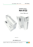
FnIO EtherCAT Network Adaptor NA-9186
FnIO S-Series
EtherCAT Network Adaptor
NA-9186
(EtherCAT)
User Manual
Version 1.02
2013 CREVIS Co.,Ltd
Copyright(C) CREVIS Co.,Ltd
Support +82-31-899-4599
URL : www.crevis.co.kr
2
FnIO EtherCAT Network Adaptor NA-9186
FnIO S-Series
DOCUMENT CHANGE SUMMARY
REV
1.0
1.01
1.02
PAGE
REMARKS
New
Document
DATE
EDITOR
2012/08/20
JE Kang
2012/11/22
JE Kang
10
Add Error LED
25
Add “IO Guide Link Test”
6
Add Certification
2013/2/14
JE Kang
Changed Crevis TEL
2013/4/4
JE KANG
Copyright(C) CREVIS Co.,Ltd
Support +82-31-899-4599
URL : www.crevis.co.kr
3
FnIO EtherCAT Network Adaptor NA-9186
FnIO S-Series
CONTENTS
1.
Important Notes .............................................................................................................................................................................. 5
1.1.
2.
1.1.1.
Symbols ............................................................................................................................................................................ 6
1.1.2.
Safety Notes ................................................................................................................................................................... 6
1.1.3.
Certification ..................................................................................................................................................................... 6
Specification ....................................................................................................................................................................................... 7
2.1.
2.1.1.
2.2.
5.
NA-9186 (EtherCAT) ................................................................................................................................................... 7
Specification ................................................................................................................................................................... 8
General Specification .................................................................................................................................................. 8
2.2.2.
Interface Specification................................................................................................................................................ 9
LED Indicator ................................................................................................................................................................10
2.3.1.
Module Status LED (MOD) ....................................................................................................................................10
2.3.2.
Current Running Status LED (RUN) ...................................................................................................................10
2.3.3.
Error Status LED (ERR) .............................................................................................................................................10
2.3.4.
Expansion Module Status LED (I/O) ..................................................................................................................11
2.3.5.
Field Power Status LED ...........................................................................................................................................11
Dimension .........................................................................................................................................................................................12
3.1.
4.
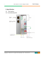
The Interface .................................................................................................................................................................. 7
2.2.1.
2.3.
3.
Safety Instruction ......................................................................................................................................................... 6
NA-9186 .........................................................................................................................................................................12
Mechanical Setup ..........................................................................................................................................................................13
4.1.
Total Expansion ...........................................................................................................................................................13
4.2.
Plugging and Removal of the Components. ................................................................................................13
4.3.
Internal FnBus/Field Power Contacts ................................................................................................................14
MODBUS Electrical Interface ....................................................................................................................................................15
Copyright(C) CREVIS Co.,Ltd
Support +82-31-899-4599
URL : www.crevis.co.kr
4
FnIO EtherCAT Network Adaptor NA-9186
5.1.
FnIO S-Series
FnBus System ...............................................................................................................................................................15
FnBus Pin Description .................................................................................................................................................................16
5.2.
5.2.1.
NA-9186 RJ-45 Socket ............................................................................................................................................17
5.2.2.
I/O Process Image Map ..........................................................................................................................................18
5.3.
7.
Example ..........................................................................................................................................................................19
5.3.1.
Example of Input Process Image(Input Register) Map.............................................................................19
5.3.2.
Example of Output Process Image(Output Register) Map .....................................................................20
5.4.
6.
EtherCAT Electrical Interface .................................................................................................................................17
How to use the NA-9186 .......................................................................................................................................21
5.4.1.
The Procedure of Configuration with Tools ..................................................................................................21
5.4.2.
IO Guide Link Test (Communication with IO Guide) ................................................................................25
ETHERCAT BASICS .........................................................................................................................................................................27
6.1.
EtherCAT Protocol .....................................................................................................................................................27
6.2.
EtherCAT State Machine .........................................................................................................................................27
6.3.
EtherCAT Mailbox ......................................................................................................................................................29
6.4.
CoE Interface – parameter management in the EtherCAT system .....................................................32
6.5.
EtherCAT Reference ..................................................................................................................................................33
Trouble Shooting ...........................................................................................................................................................................34
7.1.
How to diagnose by LED indicator ...................................................................................................................34
APPENDIX A ...............................................................................................................................................................................................36
A.1. Product List ..................................................................................................................................................................................36
A.2. Glossary .........................................................................................................................................................................................38
Copyright(C) CREVIS Co.,Ltd
Support +82-31-899-4599
URL : www.crevis.co.kr
5
FnIO EtherCAT Network Adaptor NA-9186
FnIO S-Series
1. Important Notes
Solid state equipment has operational characteristics differing from those of electromechanical equipment.
Safety Guidelines for the Application, Installation and Maintenance of Solid State Controls describes some important
differences between solid state equipment and hard-wired electromechanical devices.
Because of this difference, and also because of the wide variety of uses for solid state equipment, all persons
responsible for applying this equipment must satisfy themselves that each intended application of this equipment is
acceptable.
In no event will CREVIS be responsible or liable for indirect or consequential damages resulting from the use or
application of this equipment.
The examples and diagrams in this manual are included solely for illustrative purposes. Because of the many variables
and requirements associated with any particular installation, CREVIS cannot assume responsibility or liability for actual
use based on the examples and diagrams.
Warning!
If you don’t follow the directions, it could cause a personal injury, damage to the equipment or explosion
Do not assemble the products and wire with power applied to the system. Else it may cause an electric arc, which
can result into unexpected and potentially dangerous action by field devices. Arching is explosion risk in
hazardous locations. Be sure that the area is non-hazardous or remove system power appropriately before
assembling or wiring the modules.
Do not touch any terminal blocks or IO modules when system is running. Else it may cause the unit to an electric
shock or malfunction.
Keep away from the strange metallic materials not related to the unit and wiring works should be controlled by the
electric expert engineer. Else it may cause the unit to a fire, electric shock or malfunction.
Caution!
If you disobey the instructions, there may be possibility of personal injury, damage to equipment or
explosion. Please follow below Instructions.
Check the rated voltage and terminal array before wiring. Avoid the circumstances over 55℃ of temperature.
Avoid placing it directly in the sunlight.
Avoid the place under circumstances over 85% of humidity.
Do not place Modules near by the inflammable material. Else it may cause a fire.
Do not permit any vibration approaching it directly.
Go through module specification carefully, ensure inputs, output connections are made with the specifications. Use
standard cables for wiring.
Use Product under pollution degree 2 environment.
Copyright(C) CREVIS Co.,Ltd
Support +82-31-899-4599
URL : www.crevis.co.kr
6
FnIO EtherCAT Network Adaptor NA-9186
1.1.
FnIO S-Series
Safety Instruction
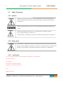
1.1.1. Symbols
Identifies information about practices or circumstances that can cause an explosion in a
hazardous environment, which may lead to personal injury or death property damage or
economic loss.
Identifies information that is critical for successful application and understanding of the
product.
Identifies information about practices or circumstances that can lead to personal
injury, property damage, or economic loss.
Attentions help you to identity a hazard, avoid a hazard, and recognize the consequences.
1.1.2. Safety Notes
The modules are equipped with electronic components that may be destroyed by electrostatic
discharge. When handling the modules, ensure that the environment (persons, workplace and
packing) is well grounded. Avoid touching conductive components, e.g. FnBUS Pin.
1.1.3. Certification
c-UL-us UL Listed Industrial Control Equipment, certified for U.S. and Canada
See UL File E235505
CE Certificate
EN 61000-6-2; Industrial Immunity
EN 61000-6-4; Industrial Emissions
FCC
RoHS (EU, China)
Copyright(C) CREVIS Co.,Ltd
Support +82-31-899-4599
URL : www.crevis.co.kr
7
FnIO EtherCAT Network Adaptor NA-9186
2. Specification
2.1.
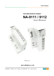
The Interface
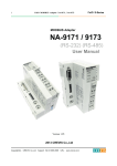
2.1.1. NA-9186 (EtherCAT)
Copyright(C) CREVIS Co.,Ltd
Support +82-31-899-4599
URL : www.crevis.co.kr
FnIO S-Series
8
FnIO EtherCAT Network Adaptor NA-9186
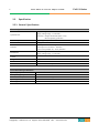
2.2.
Specification
2.2.1. General Specification
General Specification
Supply voltage : 24Vdc nominal
Supply voltage range : 11~28.8Vdc
Protection : Output current limit (Min. 1.5A)
Reverse polarity protection
100mA typical @24Vdc
1.5A @5Vdc
System power to internal logic : Non-isolation
System power to I/O driver : Isolation
System to Physial(RJ-45) : Trans, Isolation
Supply voltage : 24Vdc nominal
Supply voltage range : 11~28.8Vdc
System Power
Power Dissipation
Current for I/O Module
Isolation
Field Power
Max. Current Field Power
Contact
Weight
Module Size
Environment Condition
DC 10A Max.
150g
54mm x 99mm x 70mm
Refer to Environment Specification
Environmental Specifications
Operating Temperature
-20℃ to 55℃
Non-Operating Temperature
-40℃ to 85℃
5%~90% non-condensing
2000m
DIN rail
Relative Humidity
Operating Altitude
Mounting
Copyright(C) CREVIS Co.,Ltd
Support +82-31-899-4599
URL : www.crevis.co.kr
FnIO S-Series
9
FnIO EtherCAT Network Adaptor NA-9186
FnIO S-Series
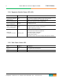
2.2.2. Interface Specification
Interface Specification, NA-9186 (EtherCAT)
Adapter Type
Max. Expansion Module
Max. Input Size
Max. Output Size
Data Baud Rate
Max. Nodes
Interface Connector
Mac Address / IP Address
Indicator
Module Location
Field Power Detection
Configuration Tool
EtherCAT Slave Node
32 slots
252 bytes (2016 points)
252 bytes (2016 points)
100Mbps
65,535
RJ-45 Socket 2ports (ECAT IN→IN, ECAT OUT→OUT)
No need
5 LEDs (Front Window)
- 1 Green/Red, Module Status (MOD)
- 1 Green, Current Running Status (RUN)
- 1 Green/Red, Error Status (ERR)
- 1 Green/Red, Expansion I/O Module Status (I/O)
- 1 Green, Field Power Status
2 LEDs (each RJ-45 Connector)
- 1 Yellow Link, Active
- 1 Green Not used
Starter module – left side of FnIO system
About 11Vdc
IO Guide Pro
Configuration Port
Node
Baud rate
Modbus/RS-232
(fixed)
115200
(fixed)
(fixed)
Data bit
8
Parity bit
No parity (fixed)
Stop bit
1
(fixed)
3M mini Clamp Plug (371 series)
- Modbus RS232 IN
IN RS232 Serial Connector
- Opposite direction
Connector
Cable Type
Copyright(C) CREVIS Co.,Ltd
1
Support +82-31-899-4599
URL : www.crevis.co.kr
10
FnIO EtherCAT Network Adaptor NA-9186
2.3.
FnIO S-Series
LED Indicator
2.3.1. Module Status LED (MOD)
State
LED is :
To indicate :
No Power
Off
No power is supplied to the unit.
Device Operational
Green
The unit is operating in normal condition.
Device in Standby
Flashing Green
Minor Fault
Flashing Red
Unrecoverable Fault
Red
The EEPROM parameter is not initialized yet.
Serial Number is zero value (0x00000000)
The unit has occurred recoverable fault in self-testing.
- EEPROM checksum fault
The unit has occurred unrecoverable fault in self-testing.
- Firmware fault
2.3.2. Current Running Status LED (RUN)
State
LED is :
To indicate :
Init
Off
State of the EtherCAT State Machine: INIT = Initialization
Pre-Operational
Blinking
State of the EtherCAT State Machine: PREOP = Pre-Operational
Safe-Operational
Single Flash
Initialization or
Bootstrap
Operational
Flashes
State of the EtherCAT State Machine: SAFEOP =
Safe-Operational
State of the EtherCAT State Machine: BOOT = Bootstrap (Update
of the coupler firmware)
State of the EtherCAT State Machine: OP = Operational
On
2.3.3. Error Status LED (ERR)
State
LED is :
To indicate :
No Error
Off
No Error
Invalid Configuration
Blinking
Invalid Configuration
Unsolicited State
Change
Application Watchdog
Timeout
Booting Error
Single Flash
Flashes
Booting Error
PDI Watchdog Timeout
On
Application Controller Failure
Double Flash
Copyright(C) CREVIS Co.,Ltd
Local Error
Process Data Watchdog Timeout / EtherCAT Watchdog Timeout
Support +82-31-899-4599
URL : www.crevis.co.kr
11
FnIO EtherCAT Network Adaptor NA-9186
FnIO S-Series
2.3.4. Expansion Module Status LED (I/O)
State
Not Powered
No Expansion Module
FnBus On-line,
Do not Exchanging I/O
FnBus Connection,
Run Exchanging IO
LED is :
To indicate :
Off
Device has no expansion module or may not be powered
Flashing Green
FnBus is normal but does not exchanging I/O data
(Passed the expansion module configuration).
Green
Exchanging I/O data
FnBus connection fault
during exchanging IO
Red
Expansion
Configuration Failed
Flashing Red
One or more expansion module occurred in fault state.
- Changed expansion module configuration.
- FnBus communication failure.
Failed to initialize expansion module
- Detected invalid expansion module ID.
- Overflowed Input / Output Size
- Too many expansion module
- Initial protocol failure
- Mismatch vendor code between adapter and expansion module.
2.3.5. Field Power Status LED
State
Not Supplied Field
Power
Supplied Field Power
LED is :
To indicate :
Off
Not supplied 24V dc field power
Green
Supplied 24V dc field power
Copyright(C) CREVIS Co.,Ltd
Support +82-31-899-4599
URL : www.crevis.co.kr
12
FnIO EtherCAT Network Adaptor NA-9186
FnIO S-Series
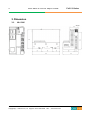
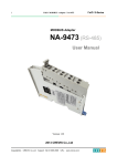
3. Dimension
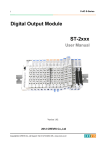
3.1.
NA-9186
(mm)
Copyright(C) CREVIS Co.,Ltd
Support +82-31-899-4599
URL : www.crevis.co.kr
13
FnIO EtherCAT Network Adaptor NA-9186
FnIO S-Series
4. Mechanical Setup
4.1.
Total Expansion
The number of the module assembly that can be connected is 32. So the maximum length is 426mm Exception.
ST-2748 is excepted to calculate maximum length because that is double width module.
4.2.
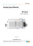
Plugging and Removal of the Components.
Before work is done on the components, the voltage supply must be turned
off.
As above figure in order to safeguard the FnIO module from jamming, it should be fixed onto the DIN rail with locking
level. To do so, fold on the upper of the locking lever.
To pull out the FnIO module, unfold the locking lever as below figure.
Copyright(C) CREVIS Co.,Ltd
Support +82-31-899-4599
URL : www.crevis.co.kr
14
FnIO EtherCAT Network Adaptor NA-9186
4.3.
FnIO S-Series
Internal FnBus/Field Power Contacts
Communication between the NA series and the expansion module as well as system / field power supply of the bus
modules is carried out via the internal bus. It is comprised of 6 data pin and 2 field power pin.
Do not touch data and field power pins in order to avoid soiling and damage
by ESD noise.
Copyright(C) CREVIS Co.,Ltd
Support +82-31-899-4599
URL : www.crevis.co.kr
15
FnIO EtherCAT Network Adaptor NA-9186
FnIO S-Series
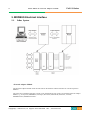
5. MODBUS Electrical Interface
5.1.
FnBus System
• Network Adapter Module
The Network Adapter Module forms the link between the field bus and the field devices with the Expansion
Modules.
The connection to different field bus systems can be established by each of the corresponding Network Adapter
Module, e.g. for SyncNet, PROFIBUS, CANopen, DeviceNet, Ethernet/IP, EtherCAT, CC-Link,
MODBUS/Serial, MODBUS/TCP etc.
Copyright(C) CREVIS Co.,Ltd
Support +82-31-899-4599
URL : www.crevis.co.kr
16
FnIO EtherCAT Network Adaptor NA-9186
• Expansion Module
The Expansion Modules are supported a variety of input and output field devices.
There are digital and analog input/output modules and special function modules.
• Two types of FnBus Message
- Service Messaging
- I/O Messaging
FnBus Pin Description
No.
Name
Description
1
2
3
4
5
6
7
8
Vcc
GND
Token Output
Serial Output
Serial Input
Reserved
Field GND
Field Vcc
System supply voltage (5V dc).
System Ground.
Token output port of Processor module.
Transmitter output port of Processor module.
Receiver input port of Processor module.
Reserved for bypass Token.
Field Ground.
Field supply voltage (24Vdc).
Copyright(C) CREVIS Co.,Ltd
Support +82-31-899-4599
URL : www.crevis.co.kr
FnIO S-Series
17
FnIO S-Series
FnIO EtherCAT Network Adaptor NA-9186
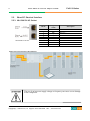
5.2.
EtherCAT Electrical Interface
5.2.1. NA-9186 RJ-45 Socket
RJ-45
Shielded RJ-45 Socket
1
2
3
4
5
6
7
8
Case
Signal
Name
TD+
TDRD+
RDShield
Description
Transmit +
Transmit Receive +
Receive -
EtherCAT Protocol Setup is like following.
The use of an incorrect supply voltage or frequency can cause severe damage
to the component.
Copyright(C) CREVIS Co.,Ltd
Support +82-31-899-4599
URL : www.crevis.co.kr
18
FnIO EtherCAT Network Adaptor NA-9186
FnIO S-Series
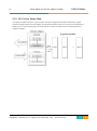
5.2.2. I/O Process Image Map
An expansion module may have 3 types of data as I/O data, configuration parameter and memory register.
The data exchange between network adapter and expansion modules is done via an I/O process image data by
FnBus protocol. The following figure shows the data flow of process image between network adapter and
expansion modules.
Copyright(C) CREVIS Co.,Ltd
Support +82-31-899-4599
URL : www.crevis.co.kr
19
FnIO S-Series
FnIO EtherCAT Network Adaptor NA-9186
5.3.
Example
5.3.1. Example of Input Process Image(Input Register) Map
Input image data depends on slot position and expansion slot data type. Input process image data is only ordered
by expansion slot position.
For example slot configuration
Slot Address
#0
#1
#2
#3
#4
#5
#6
#7
#8
#9
#10
Module Description
EtherCAT Adapter
4-discrete input
8-discrete input
2-analog input
16-discrete input
4-discrete input
8-discrete input
4-discrete input
2-analog input
16-discrete input
4-discrete input
Input Process Image
Byte
Byte #0
Byte #1
Byte #2
Byte #3
Byte #4
Byte #5
Byte #6
Byte #7
Byte #8
Byte #9
Byte #10
Byte #11
Byte #12
Byte #13
Byte #14
Byte #15
Byte #16
Byte #17
Bit 7
Copyright(C) CREVIS Co.,Ltd
Bit 6
Bit 5
Empty, Always 0
Bit 4
Bit 2
Bit 1
Bit 0
Discrete Input 4 pts (Slot#1)
Discrete Input 8 pts (Slot#2)
Analog Input Ch0 low byte (Slot#3)
Analog Input Ch0 high byte (Slot#3)
Analog Input Ch1 low byte (Slot#3)
Analog Input Ch1 high byte (Slot#3)
Discrete Input low 8 pts (Slot#4)
Discrete Input high 8 pts (Slot#4)
Empty, Always 0
Discrete Input 4 pts (Slot#5)
Discrete Input 8 pts (Slot#6)
Empty, Always 0
Discrete Input 4 pts (Slot#7)
Analog Input Ch0 low byte (Slot#8)
Analog Input Ch0 high byte (Slot#8)
Analog Input Ch1 low byte (Slot#8)
Analog Input Ch1 high byte (Slot#8)
Discrete Input low 8 pts (Slot#9)
Discrete Input high 8 pts (Slot#9)
Empty, Always 0
Discrete Input 4 pts (Slot#10)
Support +82-31-899-4599
Bit 3
URL : www.crevis.co.kr
20
FnIO S-Series
FnIO EtherCAT Network Adaptor NA-9186
5.3.2. Example of Output Process Image(Output Register) Map
Output image data depends on slot position and expansion slot data type. Output process image data is only
ordered by expansion slot.
For example slot configuration
Slot Address
#0
#1
#2
#3
#4
#5
#6
#7
#8
#9
#10
#11
Module Description
EtherCAT Adapter
4-discrete output
8-discrete output
2-analog output
16-discrete output
4-discrete output
8-discrete output
2-relay output
2-relay output
2-analog output
16-discrete output
4-discrete output
Output Process Image
Byte
Byte #0
Byte #1
Byte #2
Byte #3
Byte #4
Byte #5
Byte #6
Byte #7
Byte #8
Byte #9
Byte #10
Bit 7
Byte #11
Byte #12
Byte #13
Byte #14
Byte #15
Byte #16
Byte #17
Byte #18
Copyright(C) CREVIS Co.,Ltd
Bit 6
Bit 5
Bit 4
Bit 3
Bit 2
Empty, Don’t care
Bit 1
Bit 0
Discrete Output 4 pts (Slot#1)
Discrete Output 8 pts (Slot#2)
Analog Output Ch0 low byte (Slot#3)
Analog Output Ch0 high byte (Slot#3)
Analog Output Ch1 low byte (Slot#3)
Analog Output Ch1 high byte (Slot#3)
Discrete Output low 8 pts (Slot#4)
Discrete Output high 8 pts (Slot#4)
Empty, Don’t care
Discrete Output 4 pts (Slot#5)
Discrete Input 8 pts (Slot#6)
Discrete Output 2 pts
Empty, Don’t care
(Slot#7)
Discrete Output 2 pts
Empty, Don’t care
(Slot#8)
Analog Output Ch0 low byte (Slot#9)
Analog Output Ch0 high byte (Slot#9)
Analog Output Ch1 low byte (Slot#9)
Analog Output Ch1 high byte (Slot#9)
Discrete Output low 8 pts (Slot#10)
Discrete Output high 8 pts (Slot#10)
Empty, Don’t care
Discrete Output 4 pts (Slot#11)
Support +82-31-899-4599
URL : www.crevis.co.kr
21
FnIO EtherCAT Network Adaptor NA-9186
5.4.
How to use the NA-9186
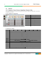
How to connect the master and slave
When you connect multiple nodes, using the IN/OUT port is connected.
IO Size and Node Address is determined sequentially from the closest thing to master.
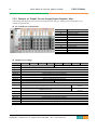
5.4.1. The Procedure of Configuration with Tools
TwinCAT
Setup XML file
“C:\TwinCAT\IO\EtherCAT” : Location of the XML file
Please copy the XML file to that folder.
Copyright(C) CREVIS Co.,Ltd
Support +82-31-899-4599
URL : www.crevis.co.kr
FnIO S-Series
22
FnIO EtherCAT Network Adaptor NA-9186
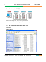
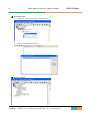
Configuration method
① Program execution
② Setup Ethernet port
A. ‘Options’ → ‘Show Real Time Ethernet Compatible Devices…’
B.
‘Installation of TwinCAT RT-Ethernet Adapter’ window, the LAN card enable.
Copyright(C) CREVIS Co.,Ltd
Support +82-31-899-4599
URL : www.crevis.co.kr
FnIO S-Series
23
FnIO EtherCAT Network Adaptor NA-9186
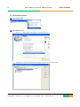
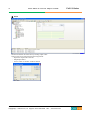
③ IO Configuration
A. IO Devices ‘right click’ and select ‘Scan Devices…’
B.
Select LAN CARD and OK click.
④ Device is created.
Copyright(C) CREVIS Co.,Ltd
Support +82-31-899-4599
URL : www.crevis.co.kr
FnIO S-Series
24
FnIO EtherCAT Network Adaptor NA-9186
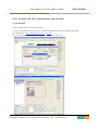
⑤ Finish
Determine whether the connection by sending output value.
Output value can be entered in the following manner.
- Export the output node of the IO
- Output Byte Select
- ‘Write’ button of ‘Online’ window clicked
- Set value
Copyright(C) CREVIS Co.,Ltd
Support +82-31-899-4599
URL : www.crevis.co.kr
FnIO S-Series
25
FnIO EtherCAT Network Adaptor NA-9186
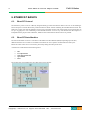
FnIO S-Series
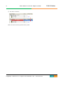
5.4.2. IO Guide Link Test (Communication with IO Guide)
Test method
Verify communication success with IO Guide.
① To use “IO Guide Pro Tool”, It is only available for Modbus 232 connector in EtherCAT Module.
② Create “New”. (File → Project File → New or Ctrl +N)
③ Scan NA-9186 & IO Modules. (Online → Automatic Scan or Shift + S)
Copyright(C) CREVIS Co.,Ltd
Support +82-31-899-4599
URL : www.crevis.co.kr
26
FnIO EtherCAT Network Adaptor NA-9186
④ Set values to ST-2328.
Make sure that the normal operation of the product.
Copyright(C) CREVIS Co.,Ltd
Support +82-31-899-4599
URL : www.crevis.co.kr
FnIO S-Series
27
FnIO EtherCAT Network Adaptor NA-9186
FnIO S-Series
6. ETHERCAT BASICS
6.1.
EtherCAT Protocol
The EtherCAT protocol uses an officially assigned EtherType inside the Ethernet Frame. The use of this EtherType
allows transport of control data directly within the Ethernet frame without redefining the standard Ethernet frame. The
frame may consist of several sub-telegrams, each serving a particular memory area of the logical process images that can
be up to 4 gigabytes in size. Addressing of the Ethernet terminals can be in any order because the data sequence is
independent of the physical order. Broadcast, Multicast and communication between slaves are possible.
6.2.
EtherCAT State Machine
The state of the EtherCAT slave is controlled via the EtherCAT State Machine (ESM). Depending upon the state,
different functions are accessible or executable in the EtherCAT slave. Specific commands must be sent by the
EtherCAT master to the device in each state, particularly during the bootup of the slave.
A distinction is made between the following states:
Init
Pre-Operational
Safe-Operational and
Operational
Boot
The regular state of each EtherCAT slave after bootup is the OP state.
Copyright(C) CREVIS Co.,Ltd
Support +82-31-899-4599
URL : www.crevis.co.kr
28
FnIO EtherCAT Network Adaptor NA-9186
FnIO S-Series
Init
After switch-on the EtherCAT slave in the Init state. No mailbox or process data communication is possible. The
EtherCAT master initializes sync manager channels 0 and 1 for mailbox communication.
Pre-Operational (Pre-Op)
During the transition between Init and Pre-Op the EtherCAT slave checks whether the mailbox was initialized
correctly.
In Pre-Op state mailbox communication is possible, but not process data communication. The EtherCAT master
initializes the sync manager channels for process data (from sync manager channel 2), the FMMU channels and,
if the slave supports configurable mapping, PDO mapping or the sync manager PDO assignment. In this state the
settings for the process data transfer and perhaps terminal-specific parameters that may differ from the default
settings are also transferred.
Safe-Operational (Safe-Op)
During transition between Pre-Op and Safe-Op the EtherCAT slave checks whether the sync manager channels
for process data communication and, if required, the distributed clocks settings are correct. Before it
acknowledges the change of state, the EtherCAT slave copies current input data into the associated DP-RAM
areas of the EtherCAT slave controller (ECSC).
In Safe-Op state mailbox and process data communication is possible, although the slave keeps its outputs in a
safe state, while the input data are updated cyclically.
Operational (Op)
Before the EtherCAT master switches the EtherCAT slave from Safe-Op to Op it must transfer valid output data.
In the Op state the slave copies the output data of the masters to its outputs. Process data and mailbox
communication is possible.
Boot
In the Boot state the slave firmware can be updated. The Boot state can only be reached via the Init state.
In the Boot state mailbox communication via the file access over EtherCAT (FoE) protocol is possible, but no
other mailbox communication and no process data communication.
Copyright(C) CREVIS Co.,Ltd
Support +82-31-899-4599
URL : www.crevis.co.kr
29
FnIO EtherCAT Network Adaptor NA-9186
6.3.
FnIO S-Series
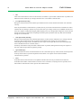
EtherCAT Mailbox
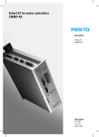
The device profiles describe the application parameters and the functional behavior of the devices including the
device class-specific state machines. For many device classes, fieldbus technology already offers reliable device
profiles, for example for I/O devices, drives or valves. Users are familiar with these profiles and the associated
parameters and tools. No EtherCAT-specific device profiles have therefore been developed for these device classes.
Instead, simple interfaces for existing device profiles are being offered (see Fig. 1).
This greatly assists users and device manufacturers alike during the migration from the existing fieldbus to
EtherCAT. At the same time the EtherCAT specification keeps it simple because all the protocols are optional.
The device manufacturer only has to implement the protocol that the device application needs.
<Fig. 1> Several Device Profiles and Protocols can co-exist side by side
CAN application layer over EtherCAT (CoE)
CANopen® device and application profiles are available for a wide range of device classes and applications,
ranging from I/O components, drives, encoders, proportional valves and hydraulic controllers to application
profiles for plastic or textile machinery, for example. EtherCAT can provide the same communication
mechanisms as the familiar CANopen [1] mechanisms: object dictionary, PDO (process data objects) and SDO
(service data objects) – even the network management is comparable. EtherCAT can thus be implemented with
minimum effort on devices equipped with CANopen. Large parts of the CANopen firmware can be reused.
Objects can optionally be expanded in order to account for the larger bandwidth offered by EtherCAT.
<Refer to 6.4>
Copyright(C) CREVIS Co.,Ltd
Support +82-31-899-4599
URL : www.crevis.co.kr
30
FnIO EtherCAT Network Adaptor NA-9186
FnIO S-Series
Servo drive profile according to IEC 61800-7-204(SERCOS) (SoE)
SERCOS interface™ is acknowledged as a high-performance real-time communication interface, particularly
for motion control applications. The SERCOS profile for servo drives and the communication technology are
covered by the IEC 61800-7-204 standard. The mapping of this profile to EtherCAT (SoE) is specified in part
304 [2]. The service channel, and therefore access to all parameters and functions residing in the drive, is based
on the EtherCAT mailbox.
Here too, the focus is on compatibility with the existing protocol (access to value, attribute, name, units, etc.
of the IDNs) and expandability with regard to data length limitation. The process data, with SERCOS in the
form of AT and MDT data, are transferred using EtherCAT device protocol mechanisms. The mapping is
similar to the SERCOS mapping. The EtherCAT slave state machine can also be mapped easily to the phases of
the SERCOS protocol. EtherCAT provides advanced real-time Ethernet technology for this device profile,
which is particularly widespread in CNC applications. Optionally, the command position, speed or torque can be
transferred. Depending on the implementation, it is even possible to continue using the same configuration tools
for the drives.
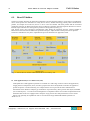
Ethernet over EtherCAT (EoE)
The EtherCAT technology is not only fully Ethernet-compatible, but also characterized by particular openness
“by design”: the protocol tolerates other Ethernet-based services and protocols on the same physical network –
usually even with minimum loss of performance. There is no restriction on the type of Ethernet device that can
be connected within the EtherCAT segment via a switchport.
The Ethernet frames are tunneled via the EtherCAT protocol, which is the standard approach for internet
applications(e.g. VPN, PPPoE (DSL), etc.). The EtherCAT network is fully transparent for the Ethernet device,
and the real-time characteristics are not impaired (see Fig. 2).
The master acts like a layer 2 switch that redirects the frames to the respective devices according to the address
information. All internet technologies can therefore also be used in the EtherCAT environment: integrated web
server, e-mail, FTP transfer, etc.
<Fig. 2> Transparent for all Ethernet Protocols
Copyright(C) CREVIS Co.,Ltd
Support +82-31-899-4599
URL : www.crevis.co.kr
31
FnIO EtherCAT Network Adaptor NA-9186
FnIO S-Series
File Access over EtherCAT (FoE)
any data structure in the device. Standardized firmware upload to devices is therefore possible, irrespective of
whether or not they support TCP/IP.
Literature
[1] EN 50325-4: Industrial communications subsystem based on ISO 11898 (CAN) for controller-device interfaces.
Part 4: CANopen.
[2] IEC 61800-7-301/304, Adjustable speed electrical power drive systems – Part 7-301: Generic interface and use
of profiles for power drive systems – Mapping of profile type 1 to network technologies – Part 7-304: Generic
interface and use of profiles for power drive systems – Mapping of profile type 4 to network technologies
Copyright(C) CREVIS Co.,Ltd
Support +82-31-899-4599
URL : www.crevis.co.kr
32
FnIO EtherCAT Network Adaptor NA-9186
6.4.
FnIO S-Series
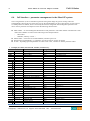
CoE Interface – parameter management in the EtherCAT system
The CiA organization (CAN in Automation) pursues among other things the goal of creating order and
exchangeability between devices of the same type by the standardization of device descriptions. For this purpose
so-called profiles are defined, which conclusively describe the changeable and unchangeable parameters of a
device. Such a parameter encompasses at least the following characteristics:
Index number – for the unambiguous identification of all parameters. The index number is divided into a main
index and a subindex in order to mark and arrange associated parameters.
Main index
Subindex, offset by a colon ‘:’
Official name – in the form of an understandable, self-descriptive text
Specification of changeability, e.g. whether it can only be read or can also be written
A value – depending upon the parameter the value can be a text, a number or another parameter index.
Example) NA-9186 (with ST-1224, ST-2414) CoE directory
Index
Name
Flags
Device type
RO
1000
Error register
RO
1001
Device name
RO
1008
Hardware version
RO
1009
Software version
RO
100A
Identity
RO
1018:0
Vendor ID
RO
┣ 1018:01
Product Code
RO
┣ 1018:02
1018:03
Revision
RO
┣
Serial Number
RO
┣ 1018:04
Release date
RO
┗ 1018:05
Error
Settings
RO
10F1:0
10F1:01
Local
Error
Reaction
RO
┣
Sync Error Counter Limit
RO
┗ 10F1:02
Slot#2, ST-2414, RxPDO
RO
1601:0
SubIndex 001
RO
┗ 1601:01
Slot#1, ST-1224, TxPDO
RO
1A00:0
SubIndex 001
RO
┗ 1A00:01
Slot#2, ST-2414, TxPDO
RO
1A01:0
SubIndex
RO
┗ 1A01:01
Sync manager type
RO
1C00:0
1C00:01
SubIndex
001
RO
┣
SubIndex 002
RO
┣ 1C00:02
SubIndex 003
RO
┣ 1C00:03
1C00:04
SubIndex
004
RO
┗
RxPDO assign
RO
1C12:0
SubIndex 001
RO
┗ 1C12:01
TxPDO assign
RO
1C13:0
1C13:01
SubIndex
001
RO
┣
Copyright(C) CREVIS Co.,Ltd
Support +82-31-899-4599
Value
0x00001389(5001)
0x00 (0)
NA-9186(Crevis)
NA-9186.v1
1.001
>5<
0x0000029D (669)
0x39313836 (959526966)
0x00010001 (65537)
0x00000001 (1)
0x20120625 (538052133)
>2<
0x00000000 (0)
0x00000004 (4)
>1<
0x7010:01, 8
>1<
0x6000:01, 8
>1<
0x6010:01, 8
>4<
0x01 (1)
0x02 (2)
0x03 (3)
0x04 (4)
>0<
0x1601 (5633)
>0<
0x1A00 (6656)
URL : www.crevis.co.kr
33
FnIO EtherCAT Network Adaptor NA-9186
┗
6000:0
┗
6010:0
┗
7010:0
┗
8010:0
┣
┗
F000:0
┣
┗
F010:0
┣
┗
1C13:02
6000:01
6010:01
7010:01
8010:01
8010:02
F000:01
F000:02
F010:01
F010:02
SubIndex 002
ST-1224(Input)
Byte#0
ST-2414(Output)
Byte#0
ST-2414(Output)
Byte#0
ST-2414(Parameter)
Byte#0
Byte#1
Modular device profile
Module index distance
Maximum number of modules
Module list
SubIndex 001
SubIndex 002
RO
RO
RO P
RO
RO P
RO
RO P
RO
RW
RW
RO
RO
RO
RO
RO
RO
FnIO S-Series
0x1A01 (6657)
>1<
0x00 (0)
>1<
0x00 (0)
>1<
0x00 (0)
>2<
0x00 (0)
0x00 (0)
>2<
0x0010 (16)
0x0020 (32)
>2<
0x00001224 (4644)
0x00002414 (9236)
Index Range
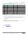
The relevant ranges for EtherCAT fieldbus users are:
x1000 : This is where fixed identity information for the device is stored, including name, manufacturer, serial
number etc., plus information about the current and available process data configurations.
x8000 : This is where the operational and functional parameters for all channels are stored, such as filter settings or
output frequency.
Other important ranges are:
x4000 : In some EtherCAT devices the channel parameters are stored here (as an alternative to the x8000 range).
x6000 : Input PDOs ("input" from the perspective of the EtherCAT master)
x7000 : Output PDOs ("output" from the perspective of the EtherCAT master)
6.5.
EtherCAT Reference
EtherCAT Reference Documents
http://www.ethercat.org
Copyright(C) CREVIS Co.,Ltd
Support +82-31-899-4599
URL : www.crevis.co.kr
34
FnIO EtherCAT Network Adaptor NA-9186
FnIO S-Series
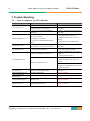
7. Trouble Shooting
7.1.
How to diagnose by LED indicator
LED Status
All LED turns off
MOD LED flashes green
MOD LED flashes red
Cause
- No power
- System power is not supplied.
- Failure of initialization EEPROM
parameter.
- Excess of expansion slot
- Excess of IO size
- Wrong IO composition
- Occurrence of EEPROM checksum
error
- Wrong address ID
- Occurrence critical error in firmware
- Failure of realization expansion Module
- None expansion Module
Action
- Check main power Cable
- Contact Sales team and send module
for repair.
- Contact Sales team and send module
for repair.
- Use expansion slot up to 32.
- Compose that IO total size is not
excess.
- Check composition I/O Module
I/O LED is red
Failure of exchanging I/O data
ERR LED blinking red
ERR LED Double
Flashing red
Invalid Configuration
- Contact Sales team and send module
for repair.
- Check connector status both NA
series and expansion module.
- Check communication cable with
Master
- Check power for master.
- Use expansion slot up to 32.
- Compose that IO total size is not
excess.
NA series notice unidentified
expansion module ID. Check status of
expansion module.
Check status of expansion IO
connection.
Will be updated
Process Data Watchdog Timeout
Will be updated
ERR LED flashing red
Booting error
Will be updated
ERR LED is red
PDI Watchdog Timeout
Will be updated
MOD LED is red
I/O LED turns off
Failure of configuration baud rate
I/O LED flashes red
Failure of initialization I/O
Copyright(C) CREVIS Co.,Ltd
Support +82-31-899-4599
URL : www.crevis.co.kr
35
FnIO EtherCAT Network Adaptor NA-9186
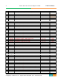
7.2.
FnIO S-Series
How to diagnose when device couldn’t communicate network
Inspection of wrong or omission cable connection.
- Check status of cable connection for each node.
- Check that all color matches between connector and cable.
- Check wire omission.
Terminator resistor
- If terminator resistor is not installed, install terminator resistor
- Check location of terminator resistor
Configuration of Node address
- Check duplication node address.
Configuration of Master
- Check configuration of master
- Check whether to do download or don’t
- Check composition is right
Configuration of communication baud rate
I/O size
Configuration of each node
Ground and environment
- Check ground is contacted
- Check environment factor (temperature, humidity, etc) is in less than regular limit
Copyright(C) CREVIS Co.,Ltd
Support +82-31-899-4599
URL : www.crevis.co.kr
36
FnIO S-Series
FnIO EtherCAT Network Adaptor NA-9186
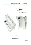
APPENDIX A
A.1. Product List
No.
ST-Number
Description
Production
Status
ID(hex)
Digital Input Module
ST-1114
4 Points, Sink(Positive), 5Vdc,
ST-111F
16 Points, Sink(Positive), 5Vdc,
ST-1124
4 Points, Source(Negative), 5Vdc,
ST-112F
16 Points, Source(Negative), 5Vdc,
ST-1214
4 Points, Sink(Positive), 12V/24Vdc,
ST-1218
8 Points, Sink(Positive), 12V/24Vdc,
ST-121F
16 Points, Sink(Positive), 12V/24Vdc,
ST-1224
4 Points, Source(Negative), 12V/24Vdc,
ST-1228
8 Points, Source(Negative), 12V/24Vdc,
ST-122F
16 Points, Source(Negative), 12V/24Vdc,
ST-1314
4 Points, Sink(Positive), 48Vdc,
ST-131F
16 Points, Sink(Positive), 48Vdc,
ST-1324
4 Points, Source(Negative), 48Vdc,
ST-132F
16 Points, Source(Negative), 48Vdc,
ST-1804
4 Points, 110Vac,
ST-1904
4 Points, 220Vac,
41
41
41
41
41
41
41
41
41
41
41
41
41
41
41
41
00
01
00
01
00
00
01
00
00
01
00
01
00
01
00
00
01
19
02
1A
03
07
13
04
08
14
05
17
06
18
09
0A
Active
Active
Active
Active
Active
Active
Active
Active
Active
Active
Active
Active
Active
Active
Active
Active
Digital Output Module
ST-2114
4 Points TTL Inverting, 5Vdc/20mA,
ST-2124
4 Points TTL Non-Inverting, 5Vdc/20mA,
ST-221F
16 Points Sink(Negative Logic), 24Vdc/0.5A,
ST-222F
16 Points Source(Positive Logic), 24Vdc/0.5A,
ST-2314
4 Points Sink(Negative Logic), 24Vdc/0.5A,
ST-2318
8 Points Sink(Negative Logic), 24Vdc/0.5A,
ST-2324
4 Points Source(Positive Logic), 24Vdc/0.5A,
ST-2328
8 Points Source(Positive Logic), 24Vdc/0.5A,
ST-2414
4 Points Sink(Negative Logic), 24Vdc/0.5A, Diagnostics
4 Points Source(Positive Logic),24Vdc/0.5A, Diagnostics
ST-2424
4 Points Sink(Negative Logic), 24Vdc/2A, Diagnostics
ST-2514
ST-2524
4 Points Source(Positive Logic), 24Vdc/2A, Diagnostics
ST-2614
4 Points Sink(Negative Logic), 24Vdc/2A,
ST-2624
4 Points Source(Positive Logic), 24Vdc/2A,
ST-2742
2 Points, 230Vac/2A, 24Vdc/2A, Relay
ST-2744
4 Points, 230Vac/2A, 24Vdc/2A, Relay
ST-2748
8 Points, 230Vac/2A, 24Vdc/2A, Relay
81
81
81
81
81
81
81
81
81
C1
C1
C1
81
81
81
81
81
00
00
01
01
00
00
00
00
00
00
00
00
00
00
00
00
00
0D
0F
15
16
0E
11
10
12
08
00 38
00 35
00 36
3B
3C
0B
51
50
Active
Active
Active
Active
Active
Active
Active
Active
Active
Active
Active
Active
Active
Active
Active
Active
Active
Copyright(C) CREVIS Co.,Ltd
Support +82-31-899-4599
URL : www.crevis.co.kr
37
FnIO S-Series
FnIO EtherCAT Network Adaptor NA-9186
ST-2792
ST-2852
ST-2924
ST-2944
ST-2734
2 Points, 230Vac/2A, 24Vdc/2A, Relay, Manual/Auto
2 Points, 12~125Vac/0.5A, Triac
4 Points, 24Vac/2A, 24Vdc/2A, 4 Points/4COM
4 Points, 24Vac/2A, 24Vdc/2A, 1 Points/1COM
4 Points, 24~220Vac,dc/0.5A, 1 Points/1COM
C1
81
81
81
81
00
00
00
00
00
01
0C
C0
C1
C2
Analog Input Module
ST-3114
4 Channels, Current, 0~20mA, 12bit
ST-3118
8 Channels, Current, 0~20mA, 12bit
ST-3134
4 Channels, Current, 0~20mA, 14bit
ST-3214
4 Channels, Current, 4~20mA, 12bit
ST-3218
8 Channels, Current, 4~20mA, 12bit
ST-3234
4 Channels, Current, 4~20mA, 14bit
ST-3274
4 Channels, Current, 4~20mA, 12bit, Sensor Connector
ST-3424
4 Channels, Voltage, 0~10Vdc, 12bit
ST-3428
8 Channels, Voltage, 0~10Vdc, 12bit
ST-3444
4 Channels, Voltage, 0~10Vdc, 14bit
ST-3474
4 Channels, Voltage, 0~10Vdc, 12bit, Sensor Connector
ST-3524
4 Channels, Voltage, -10Vdc~10Vdc, 12bit
ST-3544
4 Channels, Voltage, -10Vdc~10Vdc, 14bit
ST-3624
4 Channels, Voltage, 0~5Vdc, 12bit
ST-3644
4 Channels, Voltage, 0~5Vdc, 14bit
ST-3702
2 Channels, RTD, Status
ST-3704
4 Channels, RTD, Status
ST-3708
8 Channels, RTD, Status
ST-3802
2 Channels, TC
ST-3804
4 Channels, TC
ST-3808
8 Channels, TC
41
41
41
41
41
41
41
41
41
41
41
41
41
41
41
41
41
41
41
41
41
43
47
43
43
47
43
43
43
47
43
43
43
43
43
43
41
43
47
41
43
47
1C
82
1E
1D
83
1F
A3
20
22
22
A0
21
23
24
25
28
64
65
2A
66
67
Active
Active
Active
Active
Active
Active
Active
Active
Active
Active
Active
Active
Active
Active
Active
Active
Active
Active
Active
Active
Active
Analog Output Module
ST-4112
2 Channels, Current, 0~20mA, 12bit
ST-4114
4 Channels, Current, 0~20mA, 12bit
ST-4212
2 Channels, Current, 4~20mA, 12bit
ST-4214
4 Channels, Current, 4~20mA, 12bit
ST-4274
4 Channels, Current, 4~20mA, 12bit, Sensor Connector
ST-4422
2 Channels, Voltage, 0~10Vdc, 12bit
ST-4424
4 Channels, Voltage, 0~10Vdc, 12bit
ST-4474
4 Channels, Voltage, 0~10Vdc, 12bit, Sensor Connector
ST-4491
1 Channel, Voltage, 0~10Vdc, 12bit, Manual Type
ST-4522
2 Channels, Voltage, -10~10Vdc, 12bit
ST-4622
2 Channels, Voltage, 0~5Vdc, 12bit
ST-4911
1 Channel, Current, 0~1A, 12bit
81
81
81
81
81
81
81
81
C1
81
81
81
41
43
41
43
43
41
43
43
40
41
41
40
2C
6D
2D
6E
B3
2E
6A
B0
41 BF
2F
30
31
Active
Active
Active
Active
Active
Active
Active
Active
Active
Active
Active
Active
Copyright(C) CREVIS Co.,Ltd
Support +82-31-899-4599
URL : www.crevis.co.kr
BE
Active
Active
NEW
NEW
NEW
38
FnIO S-Series
FnIO EtherCAT Network Adaptor NA-9186
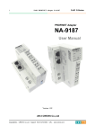
Special Module
ST-5101
ST-5111
ST-5112
ST-5114
ST-5211
ST-5212
ST-5221
ST-5231
ST-5232
ST-5351
ST-5422
ST-5442
ST-5444
ST-5641
ST-5642
ST-5651
Power Module
ST-7408
ST-7508
ST-7511
ST-7518
ST-7588
ST-7641
1 Channel, High Speed Counter, 5V Input
1 Channel, High Speed Counter, 24V Input
2 Channel, High Speed Counter, 24V Sink Input
4 Channel, High Speed Counter, 24V Sink Input
RS232 Communication, 1Channel, RTS/CTS Flow Control
RS232 Communication, 2Channel
RS422 Communication, 1Channel
RS485 Communication, 1Channel
RS485 Communication, 2Channel
SSI Interface 1CH
2 CH PWM output, 1.5A/24Vdc, source
2 CH PWM output, 0.5A/24Vdc, source
4 CH PWM output, 0.5A/24Vdc, source
1 CH Pulse output, 0.5A/24Vdc, source
2 CH Pulse output, 0.5A/24Vdc, source
1 CH Pulse output, RS422
C1
C1
C1
C1
C1
C1
C1
C1
C1
C1
C1
C1
C1
C1
C1
C1
01
01
01
03
05
0B
05
05
0B
01
05
05
0B
05
09
05
05
05
07
0F
05
0B
05
05
0B
09
01
01
03
03
07
03
8 Channels, Shield, ID Type
8 Channels, Common, 0Vdc, ID Type
1 Channel, Expansion Power, Input 24Vdc, Output
1.0A/5Vdc, ID Type
8 Channels, Common, 24Vdc, ID Type
8 Channels, Common, 0Vdc and 24Vdc, ID Type
1 Channel, Field Distributor, 5Vdc~48Vdc,
110Vac~220Vac, ID Type
02
02
00
00
E4
E5
Active
Active
02
00
E0
Active
02
02
00 E6
00 E7
Active
Active
02
00
Active
E2
A.2. Glossary
- System Power: The power for starting up CPU.
- Field Power: The power for input and output line.
- Terminator Resistor: Resistor for prevention reflected wave.
- EDS: Electronic Data Sheet.
- sinking: The method of input and output what device does not have power source.
- sourcing: The method of input and output what device have power source.
Copyright(C) CREVIS Co.,Ltd
Support +82-31-899-4599
URL : www.crevis.co.kr
34
39
4D
4C
42
43
44
45
46
9E
57
56
54
92
90
98
Active
Active
Active
Active
Active
Active
Active
Active
Active
Active
Active
Active
Active
Active
Active
Active