1
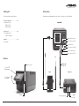
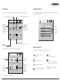
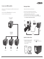
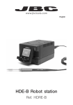
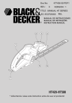
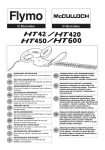
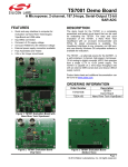
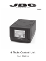
www.jbctools.com
English
4 Tools Control Unit
Ref. DME-A
w w w.jbctools.com
Packing List
Connections
The following items should be included:
Work simultaneously with up to 4 tools and 1 module + 1 pedal for each tool (Peripherals).
- 4 Tools Control Unit .............................. 1 unit
Ref. DME-1A (120V)
. DME-2A (230V)
. DME-9A (100V)
Control Unit
- Power Cord .............................................. 1 unit
Ref. 0010569 (230V)
. 0013671 (100/120V)
Equipotential connection
- Manual ....................................................... 1 unit
Ref. 0012837
RJ45 connector for LAN
USB-B connector
RJ12 connector for Robot
Power Socket and fuse
RJ12 connector for PSE
Tool
Features
Module cable
Ref. 0012709
USB-A connector
3.5” Color TFT
Touch screen
Stand
Peripheral
Tilt the display for
easy reading
Speaker
2
To another peripheral
To Pedal
Ref. P-005
3
w w w.jbctools.com
Stands & Tools
For a basic working system you need: 1 Stand, 1 Tool and 1 Cartridge or tip.
Ref. AD-SD
Stands
Tools
Precision
purpose
Handle
Ref. T210
General
purpose
Handle
Ref. T245
Ref. DN-SD
General
purpose
HD Handle
Ref. T470
Ref. AP-SD
Nitrogen
Handle
Ref. T245-NA*
Solder Feed Iron
Ref. AP130
Ref. PA-SD
Micro Tweezers
Ref. PA120
Ref. HT-SD
Thermal Tweezers
Ref. HT420
Ref. DS-SD
Micro Desoldering Iron
Ref. DS360
Ref. DR-SD
Desoldering Iron
Ref. DR560
* The MNE
Nitrogen Flow
Regulator is
required.
Cartridges
4
C210
C245
C130
C120
C420
C360
C560
5
w w w.jbctools.com
Peripherals
Compatibility
By pressing Peripherals in the main MENU, you can join tool ports with peripherals
which means each tool can work with 1 module and 1 pedal at the same time.
Select the equipment that best suit your soldering or desoldering needs.
Basic working system
Control
Unit
Control
Unit
Tool
Cartridge
Range
T210
C210
T245
C245
T470
C245
DN-SD
T245-NA*
C245
AP-SD
AP130-A
C130
PA-SD
PA120
C120
HT-SD
HT420
C420
DS-SD
DS360
C360
DR-SD
DR560
C560
Stand
AD-SD
Electric
Desoldering
Module
Ref. MSE-A
Pneumatic
Desoldering
Module
Ref. MVE-A
Nitrogen Flow
Regulator
Ref. MNE-A
Fume Extractor
Switch
Ref. FSE-A
DME
Peripherals**
MSE /
MVE
MNE
FSE
P-005
* The MNE Nitrogen Flow Regulator is required.
**If you need to connect the MS, MV, MN or FS modules, an adapter is required (Ref. IM2496).
Pedal
Ref. P-005
P-305 Pedal Kit
Connection
Box
+
Pedal
Ref. P-005
By using the Connection Box, the P-005
Pedal will work with only the tool port to
which it is connected.
Function: Enable/disable the module or make any tool enter Sleep or Hibernation modes.
This pedal will work with any module or tool regardless of the module to which it is connected.
If you do not have a module, you can link up the P-305 Pedal Kit to the tool port.
6
Function:
Makes the tool enter/skip from Sleep mode.
Tool port
connection
7
w w w.jbctools.com
Operation
Work Screen
The JBC Exclusive Heating System
The DME-A offers an intuitive user interface which provides quick access to the station parameters.
Our revolutionary technology is able to recover tip temperature extremely quickly. It means the user
can work at a lower temperature and improve the quality of soldering. The tip temperature is further
reduced thanks to the Sleep and Hibernation modes which increase the tip life by 5.
1. Work
2. Sleep
Station Information
Help for each parameter
Station Lock
PIN required
for unlocking
3. Hibernation
?
17:14
350
MENU
C245-003
ºC
Long time in
the stand
When the tool is lifted from the
stand the tip will heat up to the
selected temperature.
When the tool is in the stand,
the temperature falls to
180ºC / 360ºF (preset sleep
temperature).
After longer periods of
inactivity (pre-set to 30 min.),
the power is cut off and the
tool cools down to room
temperature.
Power indicator
Shows the %
power delivered
for each port
Selected 350º
+
Power
45%
Port
3
Cartridge
in use
Introduce the
reference for
more precise
temperatures
readings
Tool in use
Press here to
see the Ports
Screen
Simultaneous control of ports
See the information of all ports in real time when pressing the tool image from the Work screen.
?
17:14
350
17:14
MENU
ºC
8
MENU
17:14
?
MENU
+
17:14
Sleep
Hibernation
Actual Temp. 25ºC
Tool in the stand
Selected 350º
Power
45%
?
C245-003
Actual Temp. 180ºC
Port
3
Delay to hibernation: 29:30
Port
3
Port
Port
3
3
Tools Menu:
Tools Menu:
Tools Menu:
· Adjust temperature and cartridge
· Set temperature levels
· Set Sleep temperature
· Set Sleep delay
(from 0 to 9 min or no Sleep)
· Set Hibernation delay
(from 0 to 60 min or no
hibernation)
Defined cartridge
If not displayed,
go to “Cartridge
adjustment” in
Tools menu
T210
Cartridge C210-001
MENU
PORT 1
Sliding bar
See up to
4 ports
PORT 2
Tool port
Press any
port for being
displayed in the
Work Screen
350ºC
DR560
Cartridge C560-001
Tool Status
Tip temperature,
Sleep or
Hibernation
?
Sleep
Tool in the stand / 180ºC
9
w w w.jbctools.com
Menu Screen
Cartridge Adjustment
Select any option and press the station information button to display each parameter description.
Insert the cartridge model and the station will recognize its characteristics (size and shape) to provide
more accurate temperature readings.
Adjust tool settings for each port
Join station ports with modules and pedals
17:14
Personalize
the station:
Station name, PIN
activation, Screen
settings, Robot
activation, Partial
resets...
Station
Utilities
Tools
?
Peripherals
Info
Language
17:14
Counters
Registers total
and partial
hours for each
port: work, sleep,
hibernation...
Tools
Cartridge Adjust
T245 - port 3
C245-003
Temperature adjust
0ºC
Temp. level set
Off
Sleep delay
Reset
?
After
connecting
the tool,
introduce the
last 3 reference
numbers of the
cartridge.
0 min.
Multi-language
Up to 8 languages to choose from.
Utilities
System notifications
Useful additional applications that complement and support your work.
The following icons may be displayed on the status bar on the screen.
?
17:14
Insert your
tutorial
Unit Converter
ºC - ºF - K
Video
Connect a
microscope*
via USB and see
your work on
the screen
Microscope
Catalog
Files
Calculator
Graphs
USB flash drive is connected to
the USB-A.
Warning.
Press here for description.
Station is controlled by a PC.
Error.
Press here for failure description,
the type of error and how to proceed.
Convert
Monitor and
save your
soldering
process to
optimize
production
Station is controlled by a robot.
The station is being updated by a USB
flash drive.
Indicates there is a peripheral to be
installed.
*Recommended model Dino-Lite AM2011 and equivalent.
10
11
w w w.jbctools.com
Process analysis
Soldering Network
Optimize your production after analysing the information provided by the graphics.
Remotely manage and monitor as many stations as your PC can handle.
By pressing Graphics in the Utilities MENU, temperature and power figures in real
time are displayed for each port. This helps you decide how to adjust your process
or which tip to use to obtain the best quality soldering.
Graphics
Functions:
- Set all the station parameters from your PC.
- Organize groups of stations and set all their parameters at the same time.
- Store specific configurations for later uses.
- Analyze the soldering graphics of the stations on your PC and export them.
Change port
17:14
1. Download the JBC Manager software and the user manual from www.jbctools.com/manager.html
2. Connect the stations via USB-B or LAN (RJ45) and the PC will automatically detect them.
3. The icon
will appear on the screen.
?
450
100
350
75
250
50
150
25
Power (%)
JBC
Manager
software
Temperature
0
50
p1 - Temp
p1 - Power
5 sec/div
USB Hub
LAN Hub
Export graphics
Insert a USB flash drive into the USB-A
connector to start saving your soldering
process in csv format.
12
any DME station
any JBC station
13
w w w.jbctools.com
Increase x4 your DME’s possibilities
Working with Robots
Centralize control of 3 PSE Power Supply units in a single DME and work with as many as 16
tools simultaneously.
Manage and monitor the station using a Robotic system.
1. Connect the tool to the station port by means of the Converter.
2. Connect your Robot system to the station’s Robot connector (RJ12).
DB9-RJ12 Adapater available on request (Ref: 0013772).
3. Enable the Robot option in the station settings and the icon will appear:
4. Set your Robot’s commands according to the Robot Communication Protocol, available on the
website www.jbctools.com/jbcsoftware-menu-115.html.
1. Connect the DME to the PSE Control Units via the PS connector (RJ12).
2. Connect the others PSE control units as follows:
4 Tools Control Unit
Ref. DME-A
Converter
Ref. 0002747
Robot
Control
Unit
Power Supply
4 Tools Units
Ref. PSE-A
RS-232
connection
Update the station software
1. Download the update file when available at
www.jbctools.com/software.html and save it on a USB flash drive. Preferably one with no other files.
4 Tools
14
4 Tools
4 Tools
2. Insert the USB flash drive.
The icon
is diplayed while updating.
Update
file
15
w w w.jbctools.com
Maintenance
Safety
Before carrying out maintenance or storage, always allow the equipment to cool.
- Clean the station screen with a glass cleaner
or a damp cloth.
It is imperative to follow safety guidelines to prevent electric
shock, injury, fire or explosion.
Clean periodically
- Do not use the units for any purpose other than soldering or rework. Incorrect use may cause fire.
- Use a damp cloth to clean the casing and
the tool. Alcohol can only be used to clean
the metal parts.
- The power cord must be plugged into approved bases. Be sure that it is properly grounded
before use. When unplugging it, hold the plug, not the wire.
- Periodically check that the metal parts of
the tool and stand are clean so that the
station can detect the tool status.
- Do not work on electrically live parts.
- The tool should be placed in the stand when not in use in order to activate the sleep mode.
The soldering tip, the metal part of the tool and the stand may still be hot even when the station is turned off. Handle with care, including when adjusting the stand position.
- Maintain tip surface clean and tinned prior
to storage in order to avoid tip oxidation.
Rusty and dirty surfaces reduce heat
transfer to the solder joint.
- Do not leave the appliance unattended when it is on.
- Do not cover the ventilation grills. Heat can cause inflamable products to ignite.
- Periodically check all cables and tubes.
- Use a “non residue” classified flux and avoid contact with skin or eyes to prevent irritation.
- Replace a blown fuse as follows:
- Be careful with the fumes produced when soldering.
Fuse
- Keep your workplace clean and tidy. Wear appropriate protective glasses and gloves when working to avoid personal harm.
- Utmost care must be taken with liquid tin waste which can cause burns.
Fuse holder
Fuse holder
1. Pull off the fuse holder and remove the
fuse. If necessary use a tool to lever it off.
2. Press the new fuse into the fuse holder
and replace it in the station.
- This appliance can be used by children over the age of eight and also persons with reduced
physical, sensory or mental capabilities or lack of experience provided that they have been given adequate supervision or instruction concerning use of the appliance and understand the hazards involved. Children must not play with the appliance.
- Maintenance must not be carried out by children unless supervised.
- Replace any defective or damaged pieces. Use original JBC spare parts only.
- Repairs should only be performed by a JBC authorized technical service.
16
17
w w w.jbctools.com
Specifications
Exploded View
DME-1A 120V 50/60Hz. Input fuse: 6A. Output: 23.5V
DME-2A 230V 50/60Hz. Input fuse: 3.15A. Output: 23.5V
DME-9A 100V 50/60Hz. Input fuse: 8A. Output: 23.5V
- Weight: 4.3 Kg (9.3 lb)
- Dimensions: 148 x 120 x 232 mm
- Output Peak Power: 160W per tool
- Temperature Range: 90-450°C (190-840ºF)
- Idle Temp. Stability (still air): ±1.5 ºC (±3 ºF)
- Ambient Operating Temperature: 10-40 ºC (50-104 ºF)
- Tip to ground resistance: <2 ohms
- Tip to ground voltage: <2mV RMS
- USB-A / USB-B / Peripherals connectors
- RJ12 connectors: 1 for Robot and 1 for PSE Power Supply Control Unit.
- RJ45 connector for LAN (Ethernet).
Complies with CE standards
ESD protected housing “skin effect”
18
19
This product should not be thrown in the garbage.
In accordance with the European directive 2002/96/EC, electronic equipment at the end of their life
must be collected and returned to an authorized recycling facility.
www.jbctools.com
0012837-1114
Warranty
JBC’s 2 year warranty covers this equipment
against all manufacturing defects, including the
replacement of defective parts and labour.
Warranty does not cover product wear due to use
or mis-use.
In order for the warranty to be valid, equipment
must be returned, postage paid, to the dealer
where it was purchased.