1
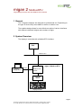
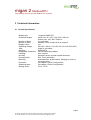
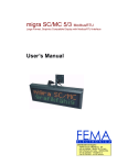
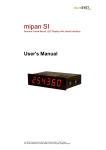
migan 2 ModbusRTU
Large Display Numeric LED with Modbus RTU Interface
User Manual
Distribuidor en España :
FEMA ELECTRÓNICA, SA
Pol. Ind. Santiga – Altimira 14 (T14 N2)
08210 Barberà del Vallès – BARCELONA
Tel. 93.72.96004 – [email protected]
Fax 93.729.6003 – w w w .fema.es
microSYST Systemelectronic GmbH, Albert-Einstein-Straße 7, 92637 Weiden, Germany
Tel. +49 961 39166-0, Fax +49 961 39166-10, www.microsyst.de, [email protected]
migan 2 ModbusRTU
Large Display Numeric LED with Modbus RTU Interface
Index
1
GENERAL
3
2
SYSTEM OVERVIEW
3
3
TECHNICAL INFORMATION
4
4
5
3.1
Overall Specification
4
3.2
Device Configuration
5
3.3
Pin Assignments and Settings
6
3.4
Device Start-Up
9
MODBUSRTU INTERFACE
10
4.1
Control Frame
12
4.2
Response Frame
14
4.3
Controlling Example
15
APPENDIX
16
5.1
Displayable Characters
16
5.2
Factory Settings (MIGAN Controller)
17
5.3
Maintenance and Care
17
5.4
Declaration of Conformity
18
5.5
Warranty / Liability
19
5.6
Versions Overview
20
Page 2
microSYST Systemelectronic GmbH, Albert-Einstein-Straße 7, 92637 Weiden, Germany
Tel. +49 961 39166-0, Fax +49 961 39166-10, www.microsyst.de, [email protected]
migan 2 ModbusRTU
Large Display Numeric LED with Modbus RTU Interface
1 General
This 7 segment displays are designed for professional use. Depending on
the type of device they are suitable for indoor or outdoor use.
The modular design allows for cost-effective models of various interfaces
with different character heights and numbers of digits.
2 System Overview
The display is controlled with a ModbusRTU interface.
PLC
Modbus RTU
Gateway
PC for
configuration
RS232
migan 2 Modbus RTU
Modbus RTU /
RS485
RS485
Controller
Board
Display Modules
Page 3
microSYST Systemelectronic GmbH, Albert-Einstein-Straße 7, 92637 Weiden, Germany
Tel. +49 961 39166-0, Fax +49 961 39166-10, www.microsyst.de, [email protected]
migan 2 ModbusRTU
Large Display Numeric LED with Modbus RTU Interface
3 Technical Information
3.1 Overall Specification
Display type:
Character heights:
Number of digits:
Number of lines:
Display colour:
Operating voltage:
View:
Interface:
Displayable characters:
Labelling:
Housing:
Housing colour:
Mounting:
Protection:
Operating temp.:
Storage temp.:
7 segment SMD LED
indoor use: 60 / 100 / 150 / 200 / 250 mm
outdoor use: 100 / 200 / 300 mm
up to 40 digits
standard 1 line, multiple lines on request
red
230 VAC / 50 Hz, 110 VAC / 60 Hz or 24 VDC ±20%
single to four-sided
ModbusRTU
see corresponding chapter
upon request
industrial version, powder coated aluminum
RAL 7016 (anthracite)
articulated arm, angle bracket, hanging on chain or
mounting frame
see chapter “Device Configuration“
see chapter “Device Configuration“
-25 to +70 °C
Page 4
microSYST Systemelectronic GmbH, Albert-Einstein-Straße 7, 92637 Weiden, Germany
Tel. +49 961 39166-0, Fax +49 961 39166-10, www.microsyst.de, [email protected]
migan 2 ModbusRTU
Large Display Numeric LED with Modbus RTU Interface
3.2 Device Configuration
Type:
for inside use
for outside use
Character height:
60 mm
100 mm
150 mm
Number of lines: ________
200 mm
250 mm
Number of digits per line: ________
View:
single sided
double sided
four sided
Operating voltage:
230 VAC / 50 Hz
110 VAC / 60 Hz
24 VDC
Protection:
IP40
IP65
IP54
Operating temperature:
with type for inside use:
0...+50 °C (standard)
Housing dimensions:
300 mm
IP _____
with type for outside use:
-20...+50 °C (standard)
-25...+50 °C (optional with heating)
_________x_________x_________mm
Housing Material:
Aluminum profile
Stainless steel
Sheet metal
Device address: _________
Page 5
microSYST Systemelectronic GmbH, Albert-Einstein-Straße 7, 92637 Weiden, Germany
Tel. +49 961 39166-0, Fax +49 961 39166-10, www.microsyst.de, [email protected]
migan 2 ModbusRTU
Large Display Numeric LED with Modbus RTU Interface
3.3 Pin Assignments and Settings
9pol. Sub-D Female Connector “ModbusRTU”
Pin
1
2
3
4
5
6
7
8
9
Assignment
RS-232 TxD
RS-232 RxD
GND Bus
+5V Bus Out
RS-485 D0 (Rx/Tx-)
RS-485 D1 (Rx/Tx+)
Remark: Depending on DIP5 of the ModbusRTU-interface (see below) either the
RS232-pins or the RS485-pins may be used. The unused pins have to be left open.
Do not use a standard RS232-cable where all pins are connected. Otherwise the
ModbusRTU-interface may be destroyed!!!
9pol. Sub-D Male Connector “Configuration, RS232”
Pin
1
2
3
4
5
6
7
8
9
Assignment
RxD
TxD
GND
Remark: This connector should not be used by the customer! The configuration is already done by microSYST and must not be changed! Otherwise the correct function of
the display can not be guaranteed!
7pol. Mains Plug (230 VAC)
Pin
1
2
(PE)
or
3pol. Circular Plug (24 VDC)
Assignm.
L1
N
PE
Pin
1
2
3
Assignment
GND
+24 VDC
PE
Page 6
microSYST Systemelectronic GmbH, Albert-Einstein-Straße 7, 92637 Weiden, Germany
Tel. +49 961 39166-0, Fax +49 961 39166-10, www.microsyst.de, [email protected]
migan 2 ModbusRTU
Large Display Numeric LED with Modbus RTU Interface
Internal LEDs
1
2
3
4
5
6
LED
1 - Bus Error
2 - Bus Ready
3 – Processing
4 – HW Settings
5 - Subnet Status
6 - Device Status
State
Description
Off
Red
Off
Green
Red
Off
Green, flashing
Off
Red
Off
Green, flashing
Green
Red
Off
Alternating Red/Green
Green
Green, flashing
Normal operation
Bus error; CRC mismatch >10%
Not powered
Normal operation (bus ready)
Bus is off line (bus not ready)
Currently not processing query
Currently processing query
Normal operation
Not configured
Power off
Initializing and not running
Running
Stopped or subnet error, or timeout
Power off
Invalid or missing configuration
Initializing
Configuration OK
Page 7
microSYST Systemelectronic GmbH, Albert-Einstein-Straße 7, 92637 Weiden, Germany
Tel. +49 961 39166-0, Fax +49 961 39166-10, www.microsyst.de, [email protected]
migan 2 ModbusRTU
Large Display Numeric LED with Modbus RTU Interface
Internal Switches
Factory settings are marked with grey colour.
ModbusRTU
Node Address
Node Address
(reserved)
1
2
…
126
127
DIP1
OFF
OFF
OFF
…
ON
ON
DIP2
OFF
OFF
OFF
…
ON
ON
DIP3
OFF
OFF
OFF
…
ON
ON
DIP4
OFF
OFF
OFF
…
ON
ON
DIP5
OFF
OFF
OFF
…
ON
ON
DIP6
OFF
OFF
ON
…
ON
ON
DIP7
OFF
ON
OFF
…
OFF
ON
ModbusRTU
Baudrate
Baudrate
(reserved)
1200 baud
2400 baud
4800 baud
9600 baud
19200 baud
38400 baud
57600 baud
DIP8
OFF
OFF
OFF
OFF
ON
ON
ON
ON
DIP1
OFF
OFF
ON
ON
OFF
OFF
ON
ON
DIP2
OFF
ON
OFF
ON
OFF
ON
OFF
ON
ModbusRTU
Parity & Stop Bits
Parity
(reserved)
No parity, 2 stop bits
Even parity, 1 stop bit
Odd parity, 1 stop bit
DIP3
OFF
OFF
ON
ON
DIP4
OFF
ON
OFF
ON
ModbusRTU
Physical Interface
Interface Type
RS232
RS485
DIP5
ON
OFF
Page 8
microSYST Systemelectronic GmbH, Albert-Einstein-Straße 7, 92637 Weiden, Germany
Tel. +49 961 39166-0, Fax +49 961 39166-10, www.microsyst.de, [email protected]
migan 2 ModbusRTU
Large Display Numeric LED with Modbus RTU Interface
Important note:
To change the setting of the DIP-switches obey the following order:
•
•
•
•
•
Disconnect the power supply.
Open the housing.
Set the dip switches as desired.
Close the housing.
Reconnect the power supply.
While the housing is open power may only be applied by qualified personnel and nothing has to be touched inside the housing at this time!
Otherwise electrical shock and danger to life may happen! Please be
careful!
3.4 Device Start-Up
Internal memory and function tests are performed at the large format display
during power-up:
• Segment test
• 8.8….
Page 9
microSYST Systemelectronic GmbH, Albert-Einstein-Straße 7, 92637 Weiden, Germany
Tel. +49 961 39166-0, Fax +49 961 39166-10, www.microsyst.de, [email protected]
migan 2 ModbusRTU
Large Display Numeric LED with Modbus RTU Interface
4 ModbusRTU Interface
The display represents a ModbusRTU-Slave and is controlled by a ModbusRTUMaster (f.e. a PLC).
To change the display contents, the ModbusRTU-Master has to write to some registers. Therefore the commands “Force Multiple Registers” (function code
16d=10H) or “Read/Write Registers” (function code 23d=17H) can be used.
Here, we assume that “registers” are counted beginning at “0”. If your PLC starts
counting at “1”, you may have to increase the register address by 1!
ModbusRTU output data must be entered as follows:
Register
(Output)
0400H
0401H
HMS
memory
address
HIGH
200H
LOW
201H
HIGH
202H
Contents Description
00H
00H
XXH
LOW
203H
XXH
0402H HIGH
LOW
0403H HIGH
LOW
0404H HIGH
LOW
0405H HIGH
204H
205H
206H
207H
208H
209H
20AH
:
:
:
01H
XXH
XXH
XXH
XXH
XXH
XXH
:
XXH
55H
:
:
:
:
:
:
Control register HIGH: static 0 (don’t change)!
Control register LOW: static 0 (don’t change)!
Trigger byte: The transmission of the frame is
executed with an increasing by one
Length byte:
Number of following bytes (ADR…CHK)
ADR
LEN
O1
O2
O3
O4
D1
:
Dn
CHK
control
frame
The length byte and the control frame (see next chapter) must be entered first.
Then, the trigger byte must be increased by one.
Thereby, the entered frame is transmitted to the MIGAN.
Page 10
microSYST Systemelectronic GmbH, Albert-Einstein-Straße 7, 92637 Weiden, Germany
Tel. +49 961 39166-0, Fax +49 961 39166-10, www.microsyst.de, [email protected]
migan 2 ModbusRTU
Large Display Numeric LED with Modbus RTU Interface
The response appears in the Modbus RTU input data:
Register
(Input)
Contents Description
0000H
HMS
memory
address
HIGH 000H
LOW 001H
HIGH 002H
9FH
00H
XXH
LOW 003H
04H
0001H
0002H HIGH
LOW
0003H HIGH
LOW
004H
005H
006H
007H
01H
02H
XXH
55H
Status register HIGH: without meaning!
Status register LOW: without meaning!
Trigger byte:
Is increased by 1 value after the reception of every response frame
Length byte:
Number of following bytes
ADR
LEN
I1
CHK
response
frame
Page 11
microSYST Systemelectronic GmbH, Albert-Einstein-Straße 7, 92637 Weiden, Germany
Tel. +49 961 39166-0, Fax +49 961 39166-10, www.microsyst.de, [email protected]
migan 2 ModbusRTU
Large Display Numeric LED with Modbus RTU Interface
4.1 Control Frame
ADR
LEN
Number of following
Device address
bytes (from O1 to CHK)
01H
XXH
►
O1
Options
Bit 7: report software version
Bit 6: 0 = Statically display the last received
data (standard)
1 = Display “----“, if no new data is
received within 5 s.
Bits 5...4: Brightness
00 = 100%
01 = 80%
10 = 60%
11 = 40%
Bit 3 = Digital output 4
Bit 2 = Digital output 3
Bit 1 = Digital output 2
Bit 0 = Digital output 1
Output will be set, if corresponding bit = 1
Continued on next page.
Page 12
microSYST Systemelectronic GmbH, Albert-Einstein-Straße 7, 92637 Weiden, Germany
Tel. +49 961 39166-0, Fax +49 961 39166-10, www.microsyst.de, [email protected]
migan 2 ModbusRTU
Large Display Numeric LED with Modbus RTU Interface
►
O2
Output format
Bits 7...4: Physical number of digits (bit coded)
0001...1111 = 1...15 digits
0000
= ASCII representation with up to 40 digits
Bit 3:
Mode
0 = LSB first
1 = MSB first
Bits 2...0: Data type*
max. number of digits
000 = unsigned CHAR (0...255)
3
001 = unsigned INT (0...65535)
5
010 = unsigned LONG (0...4294967296)
10
011 = signed CHAR (-128...127)
4
100 = signed INT (-32768...32767)
6
101 = signed LONG (-2147483648... 2147483647) 11
110 = ASCII representation
40
111 = reserved
* at value representation: right-aligned display
at ASCII representation: left-aligned display
O3
Decimal points
Bit 7 =
Bit 6 =
Bit 5 =
Bit 4 =
Bit 3 =
Bit 2 =
Bit 1 =
Bit 0 =
digit 1
digit 2
digit 3
digit 4
digit 5
digit 6
digit 7
digit 8
O4
Decimal points,
blinking
Bit 7 =
Bit 6 =
Bit 5 =
Bit 4 =
Bit 3 =
Bit 2 =
Bit 1 =
digit 9
digit 10
digit 11
digit 12
digit 13
digit 14
digit 15
D1…Dn
Data bytes
(value- or ASCII representation)
Value representation:
CHAR value: 1 byte
INT value:
2 bytes
LONG value: 4 bytes
CHK
Checksum
55H
ASCII representation (max. 80 bytes):
1 byte per character, max. 40 digits,
Bit 7 = 1: digit blinks
Bit 0 = Display
blinks
The decimal point has character code
2CH or 2EH and is always set at the
previous digit.
A point is set, if corresponding bit = 1
Controlling devices with multiple display areas (e.g. 2 lines):
The partition from O2…Dn is used repeatedly according to the number of display
areas (see example 3).
Please attend to the maximum total frame length of 150 bytes.
Page 13
microSYST Systemelectronic GmbH, Albert-Einstein-Straße 7, 92637 Weiden, Germany
Tel. +49 961 39166-0, Fax +49 961 39166-10, www.microsyst.de, [email protected]
migan 2 ModbusRTU
Large Display Numeric LED with Modbus RTU Interface
4.2 Response Frame
Digital inputs are optionally available (depending on display type).
ADR
Device address
LEN
Length
01H
02H
I1
Digital Input
Bit 7 = Event digital input 4
Bit 6 = Event digital input 3
Bit 5 = Event digital input 2
Bit 4 = Event digital input 1
CHK
Checksum
55H
Bit 3 = Status digital input 4
Bit 2 = Status digital input 3
Bit 1 = Status digital input 2
Bit 0 = Status digital input 1
Event of a digital input = 1, if it has been set at least once since the last query (f.e. with a button).
The event is deleted after every query.
Status of a digital input = 1, if it’s set at the moment.
Page 14
microSYST Systemelectronic GmbH, Albert-Einstein-Straße 7, 92637 Weiden, Germany
Tel. +49 961 39166-0, Fax +49 961 39166-10, www.microsyst.de, [email protected]
migan 2 ModbusRTU
Large Display Numeric LED with Modbus RTU Interface
4.3 Controlling Example
•
•
•
•
Display with 4 digits
Show value “1234”
Mode: LSB first
Data type: unsigned INT
STEP1: Enter ModbusRTU Output Data:
Register
(Output)
0400H HIGH
LOW
0401H HIGH
LOW
0402H HIGH
LOW
0403H HIGH
LOW
0404H HIGH
LOW
0405H HIGH
LOW
0406H HIGH
HMS
Contents Description
memory
address
200H
00H
Control register HIGH: static 0(don’t change)!
201H
00H
Control register LOW: static 0(don’t change)!
202H
00H
Trigger byte:
The transmission of the frame is executed with an in↓
creasing by one (after the entries in HMS memory ad01H
dress 203H ... 20CH have been done!)
203H
09H
Length byte
204H
01H
ADR
205H
07H
LEN
206H
00H
O1
207H
41H
O2 (4 digits, unsigned INT)
208H
00H
O3
209H
00H
O4
20AH
D2H
D1 (LOW byte of INT value “1234”)
20BH
04H
D2 (HIGH byte of INT value “1234”)
20CH
55H
CHK
STEP2: The response appears in the Modbus RTU input data:
Register
(Input)
0000H HIGH
LOW
0001H HIGH
LOW
0002H HIGH
LOW
0003H HIGH
LOW
HMS
Contents Description
memory
address
000H
9FH
Status register HIGH: without meaning!
001H
00H
Status register LOW: without meaning!
002H
00H
Trigger byte:
Is increased by 1 value after the reception of every re↓
sponse frame
01H
003H
04H
Length byte
004H
01H
ADR
005H
02H
LEN
006H
00H
I1
007H
55H
CHK
Page 15
microSYST Systemelectronic GmbH, Albert-Einstein-Straße 7, 92637 Weiden, Germany
Tel. +49 961 39166-0, Fax +49 961 39166-10, www.microsyst.de, [email protected]
migan 2 ModbusRTU
Large Display Numeric LED with Modbus RTU Interface
5 Appendix
5.1 Displayable Characters
The data bytes are ASCII coded.
Lower
Higher
0
0
1
2
3
4
5
6
7
“Blank”
1
2
3
4
5
6
7
8
9
A
B
C
D
E
F
Page 16
microSYST Systemelectronic GmbH, Albert-Einstein-Straße 7, 92637 Weiden, Germany
Tel. +49 961 39166-0, Fax +49 961 39166-10, www.microsyst.de, [email protected]
migan 2 ModbusRTU
Large Display Numeric LED with Modbus RTU Interface
5.2 Factory Settings (MIGAN Controller)
Following switches are preset and must not be changed by the user.
S2
S1
S3
Position
0
1
D
S4
S5
S6
DIP1
ON
ON
ON
DIP2
ON
ON
OFF
DIP3
ON
-
DIP4
ON
-
DIP5
OFF
-
DIP6
OFF
-
DIP7
OFF
-
DIP8
OFF
-
5.3 Maintenance and Care
Please observe the following instructions:
•
Make sure that the housing can be opened for adjustment and maintenance even after the display has been installed. Allow for adequate clearance at the back, front and top of the display unit in order to allow for sufficient ventilation (if vent slots are included).
•
Display quality is impaired by direct illumination with bright light sources
and/or direct sunlight.
•
The display must be switched off before cleaning.
•
Protect the display from excessive humidity, extreme vibration, direct
sunlight and extreme temperatures. Non-observance may lead to malfunctioning or destruction of the device. Under certain circumstances
electrical shock, fire and explosion may occur as well. Information concerning allowable ambient conditions, including recommended temperature ranges, can be found in the chapter entitled “Technical Information”.
•
The display may not be placed into service if the device and/or the power
cable are known to be damaged.
•
Do not attempt to repair the device yourself. The guarantee is rendered
null and void if the device is tampered with by unauthorised persons.
Page 17
microSYST Systemelectronic GmbH, Albert-Einstein-Straße 7, 92637 Weiden, Germany
Tel. +49 961 39166-0, Fax +49 961 39166-10, www.microsyst.de, [email protected]
migan 2 ModbusRTU
Large Display Numeric LED with Modbus RTU Interface
5.4 Declaration of Conformity
EG-Konformitätserklärung
Declaration of EC-Conformity
Produktbezeichnung:
Product name:
Produktbeschreibung:
Product description:
migan 2 ModbusRTU
Large Display Numeric LED with Modbus RTU Interface
microSYST Systemelectronic GmbH
Albert-Einstein-Straße 7
92637 Weiden
Hersteller:
Manufacturer:
Das bezeichnete Produkt stimmt mit
der folgenden Europäischen Richtlinie
überein:
We herewith confirm that the above mentioned product meets the requirements of
the following standard:
Die Übereinstimmung des bezeichneten
Produktes mit den Vorschriften der Richtlinie wird nachgewiesen durch die vollständige Einhaltung folgender Normen:
The correspondence of the above mentioned
product with these requirements is proved by
the fact that these products meet with the following single standards:
Nummer
Europäische Norm
EN61000-6-2:2006
EN61000-6-4:2007
2004/108/EG
Bezeichnung
Elektromagnetische
Verträglichkeit (EMV)
Weiden, den 04.04.2013
Harald Kilian
Geschäftsführer / General Manager
Page 18
microSYST Systemelectronic GmbH, Albert-Einstein-Straße 7, 92637 Weiden, Germany
Tel. +49 961 39166-0, Fax +49 961 39166-10, www.microsyst.de, [email protected]
migan 2 ModbusRTU
Large Display Numeric LED with Modbus RTU Interface
5.5 Warranty / Liability
For the product, liability is assumed for defects, which existed at the delivery
date according to our General Terms and Conditions.
Technically changes as well as errors are excepted. A claim for delivery of a
new product does not exist. The buyer has to check the received product immediately and indicate evident defects at the latest 24 hours after detection.
Non-observance of notification requirements is equated with acceptance of
the defect. Not immediately visible defects have to be indicated immediately
after their perception too.
Generally, defects and their symptoms must be described as accurately as
possible in order to allow for reproducibility and elimination. The buyer must
provide for access to the relevant device and all required and/or useful information at no charge and must make all of the required data and machine time
available free of charge.
The guarantee does not cover defects, which result from non-observance of
the prescribed conditions of use, or from improper handling.
If the device has been placed at the disposal of the buyer for test purposes
and has been purchased subsequent to such testing, both parties agree that
the product is to be considered “used” and that it has been purchased “as is”.
No guarantee claims may be made in such cases.
The General Terms and Conditions of microSYST Systemelectronic GmbH in
current version apply as well.
Page 19
microSYST Systemelectronic GmbH, Albert-Einstein-Straße 7, 92637 Weiden, Germany
Tel. +49 961 39166-0, Fax +49 961 39166-10, www.microsyst.de, [email protected]
migan 2 ModbusRTU
Large Display Numeric LED with Modbus RTU Interface
5.6 Versions Overview
Version
Date
1.00
1.10
19.11.13
20.11.13
Remark, Description
Document created (based on X-M32-BSXXMX-001)
Logo
Certified per DIN EN ISO 9001.
Page 20
microSYST Systemelectronic GmbH, Albert-Einstein-Straße 7, 92637 Weiden, Germany
Tel. +49 961 39166-0, Fax +49 961 39166-10, www.microsyst.de, [email protected]