1
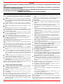
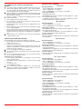
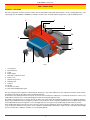
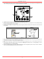
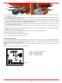
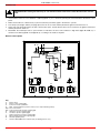
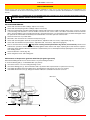
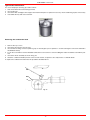
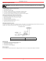
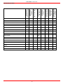
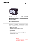
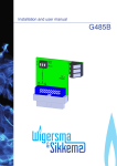
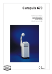
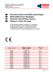
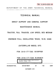
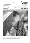
RG1025 RG1030 RG1040 Light oil burners MANUAL OF INSTALLATION - USE - MAINTENANCE BURNERS - BRUCIATORI - BRULERS - BRENNER - QUEMADORES - ГОРЕЛКИ M039144CD Rel. 3. 09/2010 WARNINGS THIS MANUAL IS SUPPLIED AS AN INTEGRAL AND ESSENTIAL PART OF THE PRODUCT AND MUST BE DELIVERED TO THE USER. INFORMATION INCLUDED IN THIS SECTION ARE DEDICATED BOTH TO THE USER AND TO PERSONNEL FOLLOWING PRODUCT INSTALLATION AND MAINTENANCE. THE USER WILL FIND FURTHER INFORMATION ABOUT OPERATING AND USE RESTRICTIONS, IN THE SECOND SECTION OF THIS MANUAL. WE HIGHLY RECOMMEND TO READ IT. CAREFULLY KEEP THIS MANUAL FOR FUTURE REFERENCE. 1) shall have qualified personnel carry out the following operations: a Remove the power supply by disconnecting the power cord from the mains. b) Disconnect the fuel supply by means of the hand-operated shut-off valve and remove the control handwheels from their spindles. GENERAL INTRODUCTION The equipment must be installed in compliance with the regulations in force, following the manufacturer’s instructions, by qualified personnel. Qualified personnel means those having technical knowledge in the field of components for civil or industrial heating systems, sanitary hot water generation and particularly service centres authorised by the manufacturer. Improper installation may cause injury to people and animals, or damage to property, for which the manufacturer cannot be held liable. Remove all packaging material and inspect the equipment for integrity. In case of any doubt, do not use the unit - contact the supplier. The packaging materials (wooden crate, nails, fastening devices, plastic bags, foamed polystyrene, etc), should not be left within the reach of children, as they may prove harmful. Before any cleaning or servicing operation, disconnect the unit from the mains by turning the master switch OFF, and/or through the cutout devices that are provided. Make sure that inlet or exhaust grilles are unobstructed. In case of breakdown and/or defective unit operation, disconnect the unit. Make no attempt to repair the unit or take any direct action. Contact qualified personnel only. Units shall be repaired exclusively by a servicing centre, duly authorised by the manufacturer, with original spare parts. Failure to comply with the above instructions is likely to impair the unit’s safety. To ensure equipment efficiency and proper operation, it is essential that maintenance operations are performed by qualified personnel at regular intervals, following the manufacturer’s instructions. When a decision is made to discontinue the use of the equipment, those parts likely to constitute sources of danger shall be made harmless. In case the equipment is to be sold or transferred to another user, or in case the original user should move and leave the unit behind, make sure that these instructions accompany the equipment at all times so that they can be consulted by the new owner and/or the installer. For all the units that have been modified or have options fitted then original accessory equipment only shall be used. This unit shall be employed exclusively for the use for which it is meant. Any other use shall be considered as improper and, therefore, dangerous. The manufacturer shall not be held liable, by agreement or otherwise, for damages resulting from improper installation, use and failure to comply with the instructions supplied by the manufacturer. Special warnings Make sure that the burner has, on installation, been firmly secured to the appliance, so that the flame is generated inside the appliance firebox. Before the burner is started and, thereafter, at least once a year, have qualified personnel perform the following operations: a set the burner fuel flow rate depending on the heat input of the appliance; b set the flow rate of the combustion-supporting air to obtain a combustion efficiency level at least equal to the lower level required by the regulations in force; c check the unit operation for proper combustion, to avoid any harmful or polluting unburnt gases in excess of the limits permitted by the regulations in force; d make sure that control and safety devices are operating properly; e make sure that exhaust ducts intended to discharge the products of combustion are operating properly; f on completion of setting and adjustment operations, make sure that all mechanical locking devices of controls have been duly tightened; g make sure that a copy of the burner use and maintenance instructions is available in the boiler room. In case of a burner shut-down, reser the control box by means of the RESET pushbutton. If a second shut-down takes place, call the Technical Service, without trying to RESET further. The unit shall be operated and serviced by qualified personnel only, in compliance with the regulations in force. 3) GENERAL INSTRUCTIONS DEPENDING ON FUEL USED 3a) ELECTRICAL CONNECTION 2) SPECIAL INSTRUCTIONS FOR BURNERS The burner should be installed in a suitable room, with ventilation openings complying with the requirements of the regulations in force, and sufficient for good combustion. Only burners designed according to the regulations in force should be used. This burner should be employed exclusively for the use for which it was designed. Before connecting the burner, make sure that the unit rating is the same as delivery mains (electricity, gas oil, or other fuel). Observe caution with hot burner components. These are, usually, near to the flame and the fuel pre-heating system, they become hot during the unit operation and will remain hot for some time after the burner has stopped. When the decision is made to discontinue the use of the burner, the user For safety reasons the unit must be efficiently earthed and installed as required by current safety regulations. It is vital that all saftey requirements are met. In case of any doubt, ask for an accurate inspection of electrics by qualified personnel, since the manufacturer cannot be held liable for damages that may be caused by failure to correctly earth the equipment. Qualified personnel must inspect the system to make sure that it is adequate to take the maximum power used by the equipment shown on the equipment rating plate. In particular, make sure that the system cable cross section is adequate for the power absorbed by the unit. No adaptors, multiple outlet sockets and/or extension cables are permitted to connect the unit to the electric mains. An omnipolar switch shall be provided for connection to mains, as required by the current safety regulations. The use of any power-operated component implies observance of a few basic rules, for example: - do not touch the unit with wet or damp parts of the body and/or with bare feet; - do not pull electric cables; - do not leave the equipment exposed to weather (rain, sun, etc.) unless expressly required to do so; - do not allow children or inexperienced persons to use equipment; The unit input cable shall not be replaced by the user. In case of damage to the cable, switch off the unit and contact qualified personnel to replace. When the unit is out of use for some time the electric switch supplying all the power-driven components in the system (i.e. pumps, burner, etc.) should be switched off. 3 DIRECTIVES AND STANDARDS Gas burners European directives: - Directive 2009/142/EC - Gas Appliances; - Directive 2006/95/EC on low voltage; - Directive 2004/108/EC on electromagnetic compatibility Harmonised standards : -UNI EN 676 (Gas Burners; -CEI EN 60335-1(Household and similar electrical appliances - Safety. Part 1: General requirements; - EN 50165 (Electrical equipment of non-electric appliances for household and similar purposes. Safety requirements. 3b) FIRING WITH GAS, LIGHT OIL OR OTHER FUELS GENERAL The burner shall be installed by qualified personnel and in compliance with regulations and provisions in force; wrong installation can cause injuries to people and animals, or damage to property, for which the manufacturer cannot be held liable. Before installation, it is recommended that all the fuel supply system pipes be carefully cleaned inside, to remove foreign matter that might impair the burner operation. Before the burner is commissioned, qualified personnel should inspect the following: a the fuel supply system, for proper sealing; b the fuel flow rate, to make sure that it has been set based on the firing rate required of the burner; c the burner firing system, to make sure that it is supplied for the designed fuel type; d the fuel supply pressure, to make sure that it is included in the range shown on the rating plate; e the fuel supply system, to make sure that the system dimensions are adequate to the burner firing rate, and that the system is equipped with all the safety and control devices required by the regulations in force. When the burner is to remain idle for some time, the fuel supply tap or taps should be closed. Light oil burners European directives: - Directive 2006/95/EC on low voltage; - Directive 2004/108/EC on electromagnetic compatibility Harmonised standards : -CEI EN 60335-1(Household and similar electrical appliances - Safety. Part 1: General requirements; - EN 50165 (Electrical equipment of non-electric appliances for household and similar purposes. Safety requirements. National standards : -UNI 7824: Monobloc nebulizer burners for liquid fuels. Characteristics and test methods SPECIAL INSTRUCTIONS FOR USING GAS Have qualified personnel inspect the installation to ensure that: a the gas delivery line and train are in compliance with the regulations and provisions in force; b all gas connections are tight; c the boiler room ventilation openings are such that they ensure the air supply flow required by the current regulations, and in any case are sufficient for proper combustion. Do not use gas pipes to earth electrical equipment. Never leave the burner connected when not in use. Always shut the gas valve off. In case of prolonged absence of the user, the main gas delivery valve to the burner should be shut off. Precautions if you can smell gas a do not operate electric switches, the telephone, or any other item likely to generate sparks; b immediately open doors and windows to create an air flow to purge the room; c close the gas valves; d contact qualified personnel. Do not obstruct the ventilation openings of the room where gas appliances are installed, to avoid dangerous conditions such as the development of toxic or explosive mixtures. Heavy oil burners European directives: - Directive 2006/95/EC on low voltage; - Directive 2004/108/EC on electromagnetic compatibility Harmonised standards : -CEI EN 60335-1 Household and similar electrical appliances - SafetyPart 1: General requirements; - EN 50165 Electrical equipment of non-electric appliances for household and similar purposes. Safety requirements. National standards : -UNI 7824: Monobloc nebulizer burners for liquid fuels. Characteristics and test methods Gas - Light oil burners European directives: - Directive 2009/142/EC - Gas Appliances; - Directive 2006/95/EC on low voltage; - Directive 2004/108/EC on electromagnetic compatibility Harmonised standards : -UNI EN 676 Gas Burners -CEI EN 60335-1(Household and similar electrical appliances - Safety. Part 1: General requirements; - EN 50165 Electrical equipment of non-electric appliances for household and similar purposes. Safety requirements. National standards : -UNI 7824: Monobloc nebulizer burners for liquid fuels. Characteristics and test methods Gas - Heavy oil burners European directives: - Directive 2009/142/EC - Gas Appliances; - Directive 2006/95/EC on low voltage; - Directive 2004/108/EC on electromagnetic compatibility Harmonised standards : -UNI EN 676 (Gas Burners; -CEI EN 60335-1(Household and similar electrical appliances - Safety. Part 1: General requirements; - EN 50165 Electrical equipment of non-electric appliances for household and similar purposes. Safety requirements. National standards : -UNI 7824: Monobloc nebulizer burners for liquid fuels. Characteristics and test methods 4 C.I.B. UNIGAS - M039144CD PART I: INSTALLATION GENERAL FEATURES This series represents monobloc burners made in die-cast aluminium housing with relative flange to work on heating generators. The output range is from 2550kW to 13000kW (according to models). They can be provided in progressive or fully-modulating version. 5 6 7 8 9 10 4 11 12 3 2 1 Fig. 1 1 2 3 4 5 6 7 8 9 10 11 12 Control panel Electrical panel Pump Burner flange Blast tube-combustion head Burner cover Oil pressure governor Adjusting cam Actuator Air inlet Air pressure switch Gun and head adjusting ring nut The fuel coming from the supply line, is pushed by the pump (11) to the nozzle and then into the combustion chamber, where the mixture between fuel and air takes place and consequently the flame. In the burners, the mixture bertween fuel and air, to perform clean and efficient combustion, is activated by atomisation of oil into very small particles. This process is achieved making pressurised oil passing through the nozzle. The pump (11) main function is to transfer oil from the tank to the nozzle in the desired quantity and pressure. To adjust this pressure, pumps are provided with a pressure regulator (except for some models for which a separate regulating valve is provided). Other pumps are provided with two pressure regulators: one for the high and one for low pressure (in double-stage systems with one nozzle). In the double-stage burners, the electric servocontrol (12), that moves the air damper, allows the optimisation of the gas flue values, as to get an efficient combustion. The position of the combustion head determines the burner’s output. The air (comburent) and fuel (light oil) are forced into the combustion chamber, as to let the flame light up. 5 C.I.B. UNIGAS - M039144CD How to interpret the burner’s “Performance curve” To check if the burner is suitable for the boiler to which it must be installled, the following parameters are needed: furnace input, in kW or kcal/h (kW = kcal/h / 860); backpressure (data are available on the boiler’s ID plate or in the user’s manual). Example: Furnace input: 600kW Backpressure: 4mbar In the “Performance curve” diagram (Fig. 2), draw a vertical line matching the furnace input value and an horizontal line matching the backpressure value. The burner is suitable if the intersection point A is inside the performance curve. Campo di lavoro bruciatori Tipo P60 Mod. M-xx.x.IT.A.0.50 - M-.xx.x.IT.A.0.65 Contropressione in camera di combustione mbar 8 7 6 5 A 4 3 2 1 0 -1 100 200 300 400 500 600 700 800 900 Potenza kW Fig. 2 Data are referred to standard conditions: atmospheric pressure at 1013mbar, ambient temperature at 15°C Burner model identification Burners are identified by burner type and model. Burner model identification is described as follows. Type RG1025 Model (1) G-. (2) PR. (3) S. (4) *. A. (5) (6) (1) BURNER TYPE RG1025 - RG1030 - RG1040 (2) FUEL G - Light oil (3) OPERATION (Available versions) PR - Progressive MD - Fully modulating (4) BLAST TUBE S - Standard (5) DESTINATION COUNTRY * - see data plate (6) BURNER VERSION A - Standard Y - Special 6 C.I.B. UNIGAS - M039144CD Specifications BURNERS RG1025 RG1030 RG1040 Output min. - max. kW 2550 - 8700 2550 - 10600 2550 - 13000 Light oil rate min. - max. kg/h 215 - 733 215 - 893 215 - 1095 Fuel Light oil Viscosity 2 - 7.4 cSt @ 40°C 840 kg/m3 Density Power supply 400V 3N ~ 50Hz Electric motor kW 18.5 22 30 Pump motor kW 4 4 5.5 Total power consumption kW 22 26.5 36 Approx. weight kg 440 470 500 Progressive - Fully modulating Operation Operating temperature °C -10 ÷ +50 Storage Temperature °C -20 ÷ +60 Intermittent Working service* NOTE: Choosing the nozzle for light oil, consider Hi equal to 42.7 MJ/kg. *NOTE ON THE BURNER WORKING SERVICE: for safety reasons, one controlled shutdown must be performed after 24 hours of countinous operation. Performance curves BACK PRESSURE IN CCOMBUSTION CHAMBER mbar RG1025 RG1030 30 30 20 20 10 10 0 2500 3500 4500 5500 6500 7500 0 2000 3000 4000 5000 6000 7000 8000 9000 10000 11000 8500 kW kW BACK PRESSURE IN CCOMBUSTION CHAMBER mbar RG1040 20 10 0 2000 3000 4000 5000 6000 7000 8000 9000 10000 11000 12000 13000 kW ìTo get the input in kcal/h, multiply value in kW by 860. Data are referred to standard conditions: atmospheric pressure at 1013mbar, ambient temperature at 15°C NOTE: The performance curve is a diagram that represents the burner performance in the type approval phase or in the laboratory tests, but does not represent the regulation range of the machine. On this diagram the maximum output point is usually reached by adjsuting the combustion head to its “MAX” position (see paragraph “Adjusting the combustion head”); the minimum output point is reached setting the combustion head to its “MIN” position. During the first ignition, the combustion head is set in order to find a compromise between the burner output and the generator specifications, that is why the minimum output may be different from the Performance curve minimum. 7 Overall dimensions (mm) A(S*) A(L*) AA RG1025 1896 2090 377 RG1030 1914 2108 377 RG1040 1961 2155 377 AB 1452 1452 1452 AC AD AE B(S*) B(L*) BB 651 25 585 350 544 641 651 25 585 350 544 657 651 25 585 386 580 657 * S: measure referred to burner provided with standard blast tube * L: measure referred to burner provided with extended blast tube ** Fit a counterflange between burner and boiler C 1546 1564 1575 CC 680 680 680 D 1502 1502 1502 E 680 680 680 F 822 822 822 G H K L 370 410 660 816 422 472 660 816 671 731** 660 816 M M16 M16 M16 N O P RR 651 460 460 265 651 460 460 265 651 460 460 265 SS 80 80 80 UU W 142 1146 142 1146 142 1146 Y Z 379 330 379 330 412 330 C.I.B. UNIGAS - M039144CD 8 Burners flange and boiler recommended drilling template C.I.B. UNIGAS - M039144CD MOUNTING AND CONNECTIONS ATTENTION: READ CAREFULLY THE “WARNINGS2 CHATPER AT THE BEGINNIG OF THIS MANUAL. Packing The burners are despatched in wooden cages whose dimensions are: 2270 x 1720 x 1360mm (L x P x H) Packing cases of this kind are affected by humidity and are not suitable for stacking. In each packing case, you will find: burner; flexible hoses; light oil filter; ceramic fibre plait to be inserted between the burner and the boiler; envelope containing this manual. H P L To get rid of the burner’s packing and in the event of scrapping of the latter, follow the procedures laid down by current laws on disposal of materials. Handling the burner Eyebolts ATTENTION! the lfting and moving operations must be carried out by specialised and trained personnel. If these operations are not carried out perfectly, there is the residual risk of the burner to overturn and fall down. As for moving the burner, use means suited for the weight to sustain (see paragraph “Technical specifications”). The burner is provided with eyebolts, for handling operations. The burner is designed to work positioned according to the picture below. For different installations, please contact the Technical Department. SIDE UP SIDE DOWN Matching the burner to the boiler The burners described in this manual have been tested with combustion chambers that comply with EN676 regulation and whose dimensions are described in the diagram . In case the burner must be coupled with boilers with a combustion chamber smaller in diameter or shorter than those described in the diagram, please contact the supplier, to verify that a correct matching is possible, with respect of the application involved. To correctly match the burner to the boiler verify the necessary input and the pressure in combustion chamber are included in the burner performance curve; otherwise the choice of the burner must be revised consulting the burner manufacturer. To choose the blast tube lenght follow the instructions of the boiler manufacturer. In absence of these consider the following: Cast-iron boilers, three pass flue boilers (with the first pass in the rear part): the blast tube must protrude no more than 100 mm into the combustion chamber. Pressurised boilers with flame reversal: in this case the blast tube must penetrate at least 50 - 100 mm into combustion chamber in respect to the tube bundle plate. The length of the blast tubes does not always allow this requirement to be met, and thus it may be necessary to use a suitably-sized 9 C.I.B. UNIGAS - M039144CD spacer to move the burner backwards or to design a blast tube tha suites the utilisation (please, contact the manifacturer). Key a) Heat output in kW b) Length of the flame tube in meters c) Flame tube firing intensity in MW/m3 d) Combustion chamber diameter (m) Fig. 4 - Firing intensity, diameter and lenght of the test flame tube as a function of the heat input in kW. Fig. 3 Fitting the burner to the boiler To perform the installation, proceed as follows: 1 drill the furnace plateas decribed in paragraph (“Overall dimensions”); 2 place the burner towards the furnace plate: lift and move the burner by means of its eyebolts placed on the top side (see”Lifting and moving the burner”); 3 screw the stud bolts (5) in the plate holes, according to the burner’s drilling plate described on paragraph “Overall dimensions”; 4 place the ceramic fibre plait on the burner flange; 5 install the burner into the boiler; 6 fix the burner to the stud bolts, by means of the fixing nuts, according to the picture below. 7 After fitting the burner to the boiler, ensure that the gap between the blast tube and the refractory lining is sealed with appropriate insulating material (ceramic fibre cord or refractory cement). ; Keys 4 1 2 3 4 5 7 Burner Fixing nut Washer Ceramic fibre plait Stud bolt Blast tube Pilot gas train 1 MANUFACTURER 2 Key 1 2 3 4 5 6 2 3 Fig. 4 Burner Gas valves Minimum gas pressure switch Gas pressure governor with filter Bellow joint Manual cutoff valve 10 4 INSTALLER 5 6 C.I.B. UNIGAS - M039144CD The pilot gas train is already installed into the burner, the connection from the filter with stabiliser to the gas supply network must be carried out. connection to the gas supply network Once the gas train in installed, execute the electrical connections for all its items (gas valves group, pressure switch). ATTENTION: once the gas train is mounted according to the diagram on Fig. 4, the gas proving test mus be performed, according to the procedure set by the laws in force. 11 C.I.B. UNIGAS - M039144CD Electrical connections Respect the basic safety rules. make sure of the connection to the earthing system. do not reverse the phase and neutral connections. fit a differential thermal magnet switch adequate for connection to the mains. ATTENTION: before executing the electrical connections, pay attention to turn the plant’s switch to OFF and be sure that the burner’s main switch is in 0 position (OFF) too. Read carefully the chapter “WARNINGS”, and the “Electrical connections” section. WARNING: The burner is provided with an electrical bridge between terminals 6 and 7; when connecting the high/ low flame thermostat, remove this bridge before connecting the thermostat. IMPORTANT: Connecting electrical supply wires to the burner teminal block MA, be sure that the ground wire is longer than phase and neutral ones. To connect the burner, please refer to the wiring diagram. To execute the electrical connections, proceed as follows: 1 remove the cover from the electrical board, unscrewing the fixing screws; 2 execute the electrical connections to the supply terminal board as shown in the attached wiring diagrams, 3 check the direction of the fan motor and pump motor (see next pargraph) 4 refit the panel cover CAUTION: adjust the thermal cut-out according to the motor rated current value. Rotation of fan motor and pump motor Once the burner’s electrical connection is accomplished, remember to check the rotation of the fan and pump motors. The motor should rotate in counterclockwise direction looking at motor’s cooling fan. In case of incorrect rotation, reverse the three-phase supply and check again the rotation of the motor. Installation diagram of light oil pipes PLEASE READ CAREFULLY THE “WARNINGS” CHAPTER AT THE BEGINNING OF THIS MANUAL. From tank To tank Fig. 5 - Double-pipe system The burner is supplied with filter and flexible hoses, all the parts upstream the filter and downstream the return flexible hose, must be installed by the customer. As far as the hoses connection, see the related paragraph. (*) Only for installations with gravity, siphon or forced circulation feed systems. If the device installed is a solenoid valve, a timer must be installed to delay the valve closing. The direct connection of the device without a timer may cause pump breaks. Key 1 Burner 2 Flexible hoses (fitted) 3 Light oil filter (fitted) 4 Automatic interceptor (*) 5 One-way valve (*) 6 Gate valve 7 Quick-closing gate-valve (outside the tank or boiler rooms) 12 C.I.B. UNIGAS - M039144CD Hydraulic diagrams for light oil supplying circuits Fig. 6 - Gravity circuit Fig. 7 - Ring circuit Fig. 8 - Suction circuit Key 1 Manual valve 2 Light oil filter 3 Light oil feeding pump 4 One way valve 5 Flexible hoses 6 Relief valve NOTE: in plants where gravity or ring feed systems are provided, install an automatic interception device (see n. 4 - Fig. 5) Pump operating principle The pumps that are used can be installed both into single-pipe and double-pipe systems. Single-pipe system: a single pipe drives the oil from the tank to the pump’s inlet. Then, from the pump, the pressurised oil is driven to the nozzle: a part comes out from the nozzle while the othe part goes back to the pump. In this system, the by-pass pulg, if provided, must be removed and the optional return port, on the pump’s body, must be sealed by steel plug and washer. Double-pipe system: as for the single pipe system, a pipe that connects the tank to the pump’s inlet is used besides another pipe that connects the pum’s return port to the tank, as well. The excess of oil goes back to the tank: this installation can be considered self-bleeding. If provided, the inside by-pass plug must be installed to avoid air and fuel passing through the pump. Burners come out from the factory provided for double-stage systems. They can be suited for single-pipe system (recommended in the case of gravity feed) as decribed before.To change from a 1-pipe system to a 2-pipe-system, insert the by-pass plug G (as for ccw-rota13 C.I.B. UNIGAS - M039144CD tion- referring to the pump shaft). Caution: Changing the direction of rotation, all connections on top and side are reversed. pipeline length in meters. Suntec T G Bleed Bleeding in two-pipe operation is automatic : it is assured by a bleed flat on the piston. In one-pipe operation, the plug of a pressure gauge port must be loosened until the air is evacuated from the system. About the use of fuel pumps Make sure that the by-pass plug is not used in a single pipe installation, because the fuel unit will not function properly and damage to the pump and burner motor could result. Do not use fuel with additives to avoid the possible formation over time of compounds which may deposit between the gear teeth, thus obstructing them. After filling the tank, wait before starting the burner. This will give any suspended impurities time to deposit on the bottom of the tank, thus avoiding the possibility that they might be sucked into the pump. On initial commissioning a "dry" operation is foreseen for a considerable length of time (for example, when there is a long suction line to bleed). To avoid damages inject some lubrication oil into the vacuum inlet. Care must be taken when installing the pump not to force the pump shaft along its axis or laterally to avoid excessive wear on the joint, noise and overloading the gears. Pipes should not contain air pockets. Rapid attachment joint should therefore be avoided and threaded or mechanical seal junctions preferred. Junction threads, elbow joints and couplings should be sealed with removable sg component. The number of junctions should be kept to a minimum as they are a possible source of leakage. Do not use PTFE tape on the suction and return line pipes to avoid the possibility that particles enter circulation. These could deposit on the pump filter or the nozzle, reducing efficiency. Always use O-Rings or mechanical seal (copper or aluminium gaskets) junctions if possible. An external filter should always be installed in the suction line upstream of the fuel unit. Oil pumps Suntec T.. Viscosity 3 - 75 cSt Oil temperature 0 - 150 °C Minimum suction pressure - 0.45 bar to prevent gasing Maximum suction pressure 5 bar Rated speed 3600 rpm max. Key 1 Inlet G3/4 2 Pressure gauge port G1/4 3 Vacuum gauge port to measure the inlet vacuum G1/4 4 To pressure adjusting valve G3/4 "Note: pump with “C” rotation. 14 C.I.B. UNIGAS - M039144CD Suntec TV Pressure governor Pressure adjustment Remove cap-nut 1 and the gasket 2, unscrew the lock nut 4. To increase pressure, twist adjusting screw 3 clockwise. To decrease the pressure, twist screw counterclockwise. Tight the lock nut 4, refit the gasket 2 and the cap nut 1. Key 1 Cap nut 2 Gasket 3 Adjusting screw 4 Lock nut 5 Gasket Fig. 9 Connecting the light oil flexible hoses To connect the flexible light oil hoses to the pump, proceed as follows, according to the pump provided: 1 remove the closing nuts A (inlet) and R (return) connections of the pump; 2 screw the rotating nut of the two flexible hoses on the pump being careful to avoid exchanging the inlet and return lines: see the arrows marked on the pump that show the inlet and the return (see prevoius paragraph). R A 15 C.I.B. UNIGAS - M039144CD Oil circuit The fuel is pushed into the pump 1 to the nozzle 3 at the delivery pressure set by the pressure governor. The solenoid valve 2 stops the fuel immission into the combustion chamber. The fuel flow rate that is not burnt goes back to the tank through the return circuit. The spill-back nozzle is feeded at constant pressure, while the return line pressure is adjusted by means of the pressure governor controlled by an actuator coupled to an adjusting cam. The fuel amount to be burnt is adjusted by means of the burner actuator according to the adjustments set (see prevoius paragraph). 3 5 6 Fig. 10 - Stand-by 2 4 1 3 5 6 Fig. 11 - Prepurge 2 4 1 3 5 6 Fig. 12 - Low flame 2 4 1 3 Fig. 13 - High flame 5 Key 1 Oil pump 2 Oil solenoid valve 3 Nozzle 4 Adjusting cam 5 Pressure gauge 6 Pressure governor 6 2 1 4 16 C.I.B. UNIGAS - M039144CD Light oil nozzles The fuel rate is adjusted by choosing a properly dimensioned nozzle (spill-back type) and adjusting the inlet and return pressure following the directions showed in the next table. NOZZLE SUPPLY PRESSURE bar 25 NOZZLE HIGH FLAME RETURN PRESSURE bar 18-21 (recommended) LOW FLAME RETURN PRESSURE bar 7 (recommended) FLUIDICS NOZZLES FLOW RATE kg/h DIMENSIONS Min Max 40 13 40 50 16 50 60 20 60 70 23 70 80 26 80 90 30 90 100 33 100 115 38 115 130 43 130 145 48 145 160 53 160 180 59 180 200 66 200 225 74 225 250 82 250 275 91 275 300 99 300 330 109 330 360 119 360 400 132 400 450 148 450 500 165 500 550 181 550 600 198 600 650 214 650 700 231 700 750 250 750 800 267 800 Fig. 14 Pressure at nozzle 25bar Pressure at nozzle 357psi Atomisation angle Pressure on return Pressure on return Up to 100kg/h Over 100kg/h % Flow rate ---------------Atomisation angle according to the return pressure _________ % Flow rate Tab. 1 Example: as for over 100kg/h nozzles, the 80% of the nozzle flow rate can be obtained with a return pressure at about 18bar (see Fig. 14). 17 C.I.B. UNIGAS - M039144CD BERGONZO NOZZLES Fig. 15 18 C.I.B. UNIGAS - M039144CD Fig. 16 19 C.I.B. UNIGAS - M039144CD Fig. 17 20 C.I.B. UNIGAS - M039144CD Fig. 18 21 C.I.B. UNIGAS - M039144CD ADJUSTMENTS Adjustments - brief description ATTENTION: before starting the burner up, be sure that the manual cutoff valves are open. Be sure that the mains switch is closed. Before starting up the burner, make sure that the return pipe to the tank is not obstructed. Any obstruction would cause the pump seal to break. .ATTENTION: During commissioning operations, do not let the burner operate with insufficient air flow (danger of formation of carbon monoxide); if this should happen, make the fuel decrease slowly until the normal combustion values are achieved. IMPORTANT! the combustion air excess must be adjusted according to the in the following chart: Recommended combustion parameters Fuel Recommended (%) CO2 Recommended (%) O2 Light oil 11.5 ÷ 13 2.9 ÷ 4.9 Adjusting the pilot gas flow rate: gas valve Brahma EG12xR and pressure stabiliser To change the pilot gas valve flow rate, proceed as follows: 1 remove the protection on the bottom of the valve, moving it counterclockwise (see next picture); 2 rotate clockwise the nut 1 as shown in to close the valve or counterclockwise to open. To perform a finest adjustment, act directly on the pressure stabiliser as follows (see next picture): 3 remove the cap T: to increase the gas pressure at the outlet use a screwdriver on the screw TR as shown in picture. Screw to increase the pressure, unscrew to decrease; once the regulation is performed, replace cap T. TR T 1 Brahma gas valve EGR*12 Pressure governor Adjust the air and fuel flow rates at the maximum output (“high flame”) first, by means of the air damper and the adjusting cam respectively. Check that the combustion parameters are in the suggested limits. Then, adjust the combustion values corresponding to the points between maximum and minimum: set the foil shape of the adjusting cam. The adjusting cam sets the air/fuel ratio in those points, regulating the opening-closing of the fuel governor. Set, now, the low flame output, acting on the low flame microswitch of the actuator in order to avoid the low flame output increasing too much or that the flues temperature gets too low to cause condensation in the chimney. 22 C.I.B. UNIGAS - M039144CD 1 Turn the burner on by means of its main switch A: if the burner locks (LED B on in the control panel) press the RESET button (C) on the control panel (see next picture) - see chapter “OPERATION” on page 28. B C A 2 check the fan motor rotation (see paragraph “Fan motor and Pump motor rotation”; 3 prime the oil pump acting directly on the related CP contactor (see next picture): check the pump motor rotation and keep pressing for some seconds until the oil circuit is charged; bleed the air from the M pressure gauge port (Fig. 19) by loosing the cap without removing it, then release the contactor and srew the cap again. 4 Suntec T.. M CP VR Fig. 19 5 6 7 8 Before starting the burner up, drive the high flame actuator microswitch matching the low flame one (in order to let the burner operates at the lowest output) to achieve safely the high flame stage. start the burner up by means of the thermostat series and wait until the pre-purge time comes to an end and that the bruner starts up; drive the burner to high flame stage, by means fo the thermostat TAB (high/low flame thermostat - see wiring diagrams), as far as fully-modulating burners, see related paragraph. Then move progressively the microswitch to higher values until it reaches the high flame position; always check the combustion values and eventually adjusting the oil pressure (see next step). 23 C.I.B. UNIGAS - M039144CD mensions Dimensions in VI SQM4... I III IV II V IV MAN III Actuator cams II I II III IV I AUTO High flame Stand-by and Ignition Low flame Stroke limitation MAN-AUTO Siemens SQM10 Siemens SQM40 9 the nozzle supply pressureis already factory-set and must not be changed. Only if necessary, adjust the supply pressure as follows (see related paragraph);insert a pressure gauge into the port shown on Fig. 20 and act on on the pump adjusting screw VR (see Fig. 19 and page 15) as to get the nozzle pressure at 25bar (see page 17). Pressure gauge port PG RP V2 SV2 Fig. 20 Fig. 21 10 in order to get the maximum oil flow rate, adjust the pressure (reading its value on the PG pressure gauge): checking always the combustion parameters, the adjustment is to be performed by means of the SV adjusting cam screw (see picture) when the cam has reached the high flame position. 11 To adjust the air flow rate in the high flame stage, loose the RA nut and screw VRA as to get the desired air flow rate: moving the rod TR towards the air damper shaft, the air damper opens and consequently the air flow rate increases, moving it far from the shaft the air damper closes and the air flow rate decreases. Note: once the procedure is perfomed, be sure that the blocking nut RA is fasten. Do not change the position of the air damper rods. TR VRA RA 12 the air and oil rate are now adjusted at the maximum power stage, go on with the point to point adjustement on the SV adjusting cam as to reach the minimum output point. 24 C.I.B. UNIGAS - M039144CD RP ID V SC SV 13 as for the point-to-point regulation in order to set the cam foil shape, move the oil low flame microswitch (cam III) a little lower than the maximum position (90°); 14 set the TAB thermostat to the minimum (as far as fully-modulating burners, see related paragraph) in order that the actuator moves progressively towards the low flame position; 15 move cam III towards the minimum to move the actuator towards the low flame until the two bearings find the adjusting screw that refers to a lower position: screw V to increase the rate, unscrew to decrease, in order to get the pressure as showed on chart/diagram on “Light oil nozzles” on page 17, according to the requested rate. 16 Move again cam III towards the minimum to meet the next screw on the adjusting cam and repeat the previous step; go on this way as to reach the desired low flame point. 17 The low flame position must never match the ignition position that is why cam III must be set 20°- 30° more than the ignition position. 18 cam IV (stroke limitation cam) must be set a little higher than the cam III to limit the output in the first seconds the flame appears; NOTE: cam IV must shift according to cam III. 19 Turn the burner off; then start it up again. If the adjustment is not correct, repeat the previous steps. 20 Replace the actuator and control panel covers. 21 Now, adjust the air pressure switch (see next parargaph). As far as fully-modulating burners, see paragraph below. Fully-modulating burners To adjust the fully-modulating burners, use the CMF switch on the burner control panel (see next picture), instead of the TAB thermostat as described on the previous paragraphs about the progressive burners. Go on adjusting the burner as described before, paying attention to use the CMF switch intead of TAB. The CMF position sets the oprating stages: to drive the burner to the high-flame stage, set CMF=1; to drive it to the low-flame stage, set CMF=2. To move the adjusting cam set CMF=1 or 2 and then CMF=0. CMF = 0 CMF = 1 CMF = 2 CMF = 3 CMF 25 stop at the current position high flame operation low flame operation automatic operation C.I.B. UNIGAS - M039144CD Adjusting the combustion head To let the burner operate at a lower output, loose the VB screw and move progressively back the combustion head towards the MIN position, by turning clockwise the VRT ring nut. Fasten VB screw when the adjustment is accomplished. VRT VB “MAX”head position head position Calibration of air pressure switch To calibrate the air pressure switch, proceed as follows: Remove the transparent plastic cap. VR Once air and gas setting have been accomplished, startup the burner. During the pre-purge phase o the operation, turn slowly the adjusting ring nut VR in the clockwise direction until the burner lockout, then read the value on the pressure switch scale and set it to a value reduced by 15%. Repeat the ignition cycle of the burner and check it runs properly. Refit the transparent plastic cover on the pressure switch. 26 C.I.B. UNIGAS - M039144CD PART II: OPERATION LIMITATIONS OF USE THE BURNER IS AN APPLIANCE DESIGNED AND CONSTRUCTED TO OPERATE ONLY AFTER BEING CORRECTLY CONNECTED TO A HEAT GENERATOR (E.G. BOILER, HOT AIR GENERATOR, FURNACE, ETC.), ANY OTHER USE IS TO BE CONSIDERED IMPROPER AND THEREFORE DANGEROUS. THE USER MUST GUARANTEE THE CORRECT FITTING OF THE APPLIANCE, ENTRUSTING THE INSTALLATION OF IT TO QUALIFIED PERSONNEL AND HAVING THE FIRST COMMISSIONING OF IT CARRIED OUT BY A SERVICE CENTRE AUTHORISED BY THE COMPANY MANUFACTURING THE BURNER. A FUNDAMENTAL FACTOR IN THIS RESPECT IS THE ELECTRICAL CONNECTION TO THE GENERATOR’S CONTROL AND SAFETY UNITS (CONTROL THERMOSTAT, SAFETY, ETC.) WHICH GUARANTEES CORRECT AND SAFE FUNCTIONING OF THE BURNER. THEREFORE, ANY OPERATION OF THE APPLIANCE MUST BE PREVENTED WHICH DEPARTS FROM THE INSTALLATION OPERATIONS OR WHICH HAPPENS AFTER TOTAL OR PARTIAL TAMPERING WITH THESE (E.G. DISCONNECTION, EVEN PARTIAL, OF THE ELECTRICAL LEADS, OPENING THE GENERATOR DOOR, DISMANTLING OF PART OF THE BURNER). NEVER OPEN OR DISMANTLE ANY COMPONENT OF THE MACHINE. OPERATE ONLY THE MAIN SWITCH, WHICH THROUGH ITS EASY ACCESSIBILITY AND RAPIDITY OF OPERATION ALSO FUNCTIONS AS AN EMERGENCY SWITCH, AND ON THE RESET BUTTON. IN CASE OF A BURNER SHUT-DOWN, RESET THE CONTROL BOX BY MEANS OF THE RESET PUSHBUTTON. IF A SECOND SHUT-DOWN TAKES PLACE, CALL THE TECHNICAL SERVICE, WITHOUT TRYING TO RESET FURTHER. WARNING: DURING NORMAL OPERATION THE PARTS OF THE BURNER NEAREST TO THE GENERATOR (COUPLING FLANGE) CAN BECOME VERY HOT, AVOID TOUCHING THEM SO AS NOT TO GET BURNT. 27 C.I.B. UNIGAS - M039144CD OPERATION ATTENTION: before starting the burner up, be sure that the manual cutoff valves. Check that the mains switch is closed. 1 2 3 4 5 Check that the burner is not in shutdown condition (light E, on), if so, release by pressing the reset button N on the burner control panel. Make sure that the set of thermostats (or pressure-switches) sends the signal to the burner to operate. The startup cycle begins with the pre-purge phase, the fan motor starts and the pilot burner ignition trasformer turns on. At the end of the pre-purge phase, the fuel solenoid valve opens, and the burner starts; few seconds later, the ignition transformer and the pilot burner switch off. Meanwhile, the air damper starts to open and few seconds later, the servocontrol switches to high flame (lights A and B, on) or remains in low flame (light B, on and light A off), according to the needs of the plant. Burner control panel I N G H B O P C A Fig. 22 Key A B C E EVG EVS G H I N O P Burner switch Burner lockout signaling light Control box release pushbutton CMF - Automatic/Manual operation switch (only for fully-modulating models) Fuel solenoid valve Solenoid valve EVG operation signaling light High flame operation signaling light Low flame operation signaling light Ignition transformer operation signaling light Overload tripped intervention signaling light Srand-by signalling lamp Siemens RWF40.00 burner modulator (fully modulating burners only) 28 E C.I.B. UNIGAS - M039144CD PART III: MAINTENANCE At least once a year carry out the maintenance operations listed below. In the case of seasonal servicing, it is recommended to carry out the maintenance at the end of each heating season; in the case of continuous operation the maintenance is carried out every 6 months. WARNING: ALL OPERATIONS ON THE BURNER MUST BE CARRIED OUT WITH THE MAINS DISCONNECTED AND THE FUEL MANAUL CUTOFF VALVES CLOSED! ATTENTION: READ CAREFULLY THE “WARNINGS” CHAPTER AT THE BEGINNIG OF THIS MANUAL.. ROUTINE MAINTENANCE Check and clean the fuel filter cartdrige, replace if necessary. Check and clean the pilot gas filter cartdrige, replace if necessary. Inspection and cleaning of the filter inside the light oil pump: filter must be thoroughly cleaned at least once in a season to ensure correct working of the fuel unit. To remove the filter, unscrew the four screws on the cover. When reassemble, make sure that the filter is mounted with the feet toward the pump body. If the gasket between cover and pump housing should be damaged, it must be replaced. An external filter should always be installed in the suction line upstream of the fuel unit. Check the fuel hoses for possible leaks. Dismantle, clean and check the combustion head (see Fig. 23). Check and clean the ignition electrode on the pilot burner, adjustment and, if necessary, replacement (Fig. 25). Check and clean the detection photoresistor, adjustment and, if necessary, replacement (page 32). Remove and clean the fuel nozzle (Important: cleaning must be performed using solvent, not metal tools!). At the end of maintenance operations after the burner reassembly, light the flame and check its shape, replacing the nozzle whenever a questionable flame shape appears. Whenever the burner is used intensely, we recommend preventively replacing the nozzle at the start of each heating season. Check the detection current (Fig. 26). Clean and grease levers and rotating parts. Maintenance of the pressure governor with filter (for ignitor gas train) Before disassmbling the device, be sure that there is no pressurised gas inside it. To check the filtering part (1) on threaded bodies (see picture): remove the bottom cover, unscrewing the fixing screws; remove the filtering part (1), clean it with water and soap, blow it with compressed air or replace it if necessary; reassemble the filtering part in its initial position checking that it is placed in its own slots (see picture); reassemble the bottom cover (3), being sure that the main bolt is centered in the bottom cover slot. filter slots 1 4 3 2 29 C.I.B. UNIGAS - M039144CD Light oil filter maintenance For correct and proper servicing, proceed as follows: 1 shut off fuel in the line section being serviced; 2 unscrew the tray; 3 remove the filter cartridge from its support and wash it with petrol or replace if necessary; check seal O-Ring, replace if necessary; 4 reassemble the tray and restore fuel flow. Removing the combustion head 1 2 3 Remove the top cover C; remove the photoresistor from its seat; unscrew the revolving connectors (E in Fig. 23) on the fuel pipes (use 2 spanners to avoid loosening the connections attached to the distributor block); 4 loosen the screw VRT to free the threaded rod AR, then screw out the 2 screws V holding the washer R and the screw VRT in position; 5 remove the whole assembly as shown in Fig. 23. 6 Clean the combustion head by means of the vacuum cleaner; scrape the scale off by means of a metallic brush.. To replace the combustion head reverse the procedure described above. C AR VRT R Fig. 23 30 C.I.B. UNIGAS - M039144CD Removing the oil gun 1 2 3 4 remove the combustion head, as described on the previous paragraph; slacken the screw VB remove the gun with the nozzle holder to rreassemble follow the procedure above in the reversed order. VB E Fig. 24 Electrode and nozzle position setting ATTENTION: avoid the ignition and detection electrodes to contact metallic parts (blast tube, head, etc.), otherwise the boiler’s operation would be compromised. Check the electrodes position after any intervention on the combustion head. To guarantee a good ignition, the masures below (in mm) must be observed (Fig. 25). A B C A= 8 mm B= 3 mm C= 8 mm Fig. 25 31 C.I.B. UNIGAS - M039144CD Replacing the ignition electrode ATTENTION: avoid the ignition and detection electrodes to contact metallic parts (blast tube, head, etc.), otherwise the boiler’s operation would be compromised. Check the electrodes position after any intervention on the combustion head. To replace the ignition electrode, proceed as follows: 1 remove the burner cover 2 disconnect the electrode cable 3 remove the combustion head (see par. “Removing the combustion head”); 4 loosen the screw that fastens the ignition electrode to the burner ignitor; 5 remove the electrode and replace it referring to the measures shown on Fig. 25. Cleaning and replacing the detection photoresistor To clean/replace the detection photoresistor, proceed as follows: 1 Disconnect the system from the electrical power supply. 2 Shut off the fuel supply 3 remove the photoresistor from its slot ; 4 if necessary, replace the photocell with a new one; 5 replace the photoresistor into its slot. Checking the detection current To measure the detection signal follow the diagram in figure. If the signal is not in the advised range, verify the electrical contacts, the cleaning of the combustion head, the position of the photoresistor and if necessary replace it. MC TERMINAL BLOCK 34 35 SCALE µA DC Fig. 26 Control box Minumum detection signal Siemens LAL 8µA Seasonal stop To stop the burner in the seasonal stop, proceed as follows: 1 turn the burner’s main switch to 0 (Off position) 2 disconnect the power mains 3 close the fuel cock of the supply line Burner disposal In case of disposal, follow the instructions according to the laws in force in your country about the “Disposal of materials”. 32 C.I.B. UNIGAS - M039144CD MAIN SWITCH OPEN LINE FUSE INTERVENTION MAX. PRESSURE SWITCH FAULT FAN THERMAL CUTOUT INTERVENTION AUXILIARY RELAIS FUSES INTERVENTION CONTROL BOX FAULT THE BURNER STOPS AND REPEATS THE CYCLE DURING OPERATION THE BURNER STOPS DURING OPERATION THE BURNER DOESN’T SWITCH TO HIGH FLAME THE BURNER STARTS AND STOPS THE BURNER DOESN’T START AND STOPS NOISY FUEL PUMP THE BURNER REPEATS PREPURGE THE BURNER DOESN’T START TROUBLESHOOTING SERVOCONTROL FAULT SMOKEY FLAME IGNITION TRANSFORMER FAULT IGNITION ELECTRODE DIRTY OR BADLY POSITIONED DIRTY NOZZLE FUEL SOLENOID VALVE DEFECTIVE PHOTORESISTOR DIRTY OR DEFECTIVE HI-LO FLAME THERMOSTAT DEFECTIVE WRONG POSITION OF SERVOCONTROL CAMS FUEL PRESSURE TOO LOW DIRTY FUEL FILTERS 33 C.I.B. UNIGAS - M039144CD SPARE PARTS Desription RG1025 RG1030 RG1040 CONTROL BOX mod.SIEMENS LAL2.25 2020420 2020420 2020420 IGNITION ELECTRODE 2080254 2080254 2080258 LIGHT OIL FILTER 2090018 2090018 2090018 GAS FILTER 2090101 2090101 2090101 FAN WHEEL 2150063 2150058 2150058 PILOT GAS PRESSURE SWITCH 2160086 2160086 2160086 AIR PRESSURE SWITCH 2160097 2160097 2160097 IGNITION TRANSFORMER 2170301 2170301 2170301 PUMP MOTOR 2180283 2180283 2180283 FAN MOTOR 2180289 2180291 2180292 3-WAYS SOLENOID VALVE mod. SIRAI 2190437 2190437 2190437 LIGHT OIL SOLENOID VALVE mod. PARKER 2190750 2190750 2190750 GAS SOLENOID VALVE mod. BRAHMA EG*R12 2190502 2190502 2190502 FLEXIBLE HOSES L=1500 1”M x 1”F 2340004 2340004 2340004 FLEXIBLE HOSES L=800 1/2”M x 1/2”F 2340027 2340027 - FLEXIBLE HOSES L=600 3/8” - - 2340049 FLEXIBLE HOSES L=385 3/8” 2340088 2340088 - FLEXIBLE HOSES L=485 3/8” 2340089 2340089 2340089 GAS FLEXIBLE HOSES 1/2”M 234FX07 234FX07 234FX07 - - 234FX24 2440013 2440054 2440054 FLEXIBLE HOSES L=347 1/2”F x 1/2”F ADJUSTING CAM FOIL ACTUATOR SIEMENS SQM10 2480004 2480004 2480004 ACTUATOR SIEMENS SQM40 24800A5 24800A5 24800A5 PHOTORESISTOR 2510003 2510003 2510003 MOTOR-PUMP PLASTIC COUPLING 2540133 2540133 2540133 PRESSURE REGULATOR 2570006 2570008 25700E6 PRESSURE REGULATOR TV40 2570036 2570036 2570036 MODULATOR (ONLY FOR FULLY-MODULATING BURNERS) 2570112 2570112 2570112 PUMP 2590148 2590148 2590148 NOZZLE (specify angle and rate when ordering) mod. FLUIDICS 2610203 2610203 2610203 COMPLETE OIL GUN 2700351 2700351 2700351 L.P.G. REDUCTION 2800125 2800125 2800125 GAS GOVERNOR WITH FILTER 2800085 2800085 2800085 COMBUSTION HEAD 3060165 30601A5 30601D1 BLAST TUBE 30910T9 30910T7 30910U6 BLAST TUBE 30910M4 30910L5 30910U7 IGNITION CABLE 6050143 6050143 6050143 NOTE: it is recommended to mention the burner ID number on the spare parts request form. ELECTRICAL WIRING DIAGRAM See the attached wiring diagrams. SE12-144: fully-modulating burners SE12-133: progressive burners ATTENTION: 1 - Electric supply 400V 50Hz 3N a.c. 2 - Don't reverse phase and neutral 3 - Make sure that the burner is properly hearted 34 APPENDIX t3’ Long preignition time: «Z» connected to terminal 15. t3n Postignition time: - «Z» must be connected to terminal 15 - With short preignition, «Z» remains on until «TSA» has elapsed connection to terminal 16. t4 Interval «BV1 – BV2» or «BV1 - LR»: On completion of «t4», voltage is present at terminal 19. The voltage is required to power «BV2» connected to auxiliary switch «v» in the actuator. t5 Interval: On completion of «t5», terminal 20 receives power. At the same time, control outputs 9 to 11 and input 8 are galvanically separated from the LAL...’s control section. LAL... is now protected against reverse voltages from the load control circuit. With the release of «LR» at terminal 20, the startup sequence of the LAL... ends. After a few idle steps (steps with no contact position changes), the sequence switch switches itself off. B Operating position of the burner SIEMENS LAL.. CONTROL BOX FOR OIL BURNERS Use Control and supervision of oil atomization burners For burners of medium to high capacity For intermittent operation (at least one controlled shutdown every 24 hours) Universally applicable for multistage or modulating burners Housing and plug-in base Made of impact-proof and heat-resistance black plastic Lockout reset button with viewing window; located behind it: Lockout warning lamp Lockout indicator coupled to the spindle of the sequence switch and visible in the transparent lockout reset button uses easy-to-remember symbols to indicate the type of fault and the point in time lockout occurred B-C Burner operation: during burner operation, «LR» drives the air damper to the nominal load or low-fire position, depending on heat demand; the release of the nominal load takes place via auxiliary switch «v» in the actuator and in the event of loss of flame during operation, the LAL... will initiate lockout. For automatic start repetition, the clearly marked wire link «B» on the plugin section of the LAL... must be cut away. C Controlled shutdown: in the case of controlled shutdown, «BV...» will immediately be closed. At the same time, the sequence switch is started to program «t6» C-D Sequence switch travels to start position «A» t6 Postpurge time: fan «M2» connected to terminal 7. Shortly after the start of «t6», terminal 10 receives power and the air damper is driven to the MIN position. Full closing of the air damper starts only shortly before «t6» has elapsed initiated by the control signal at terminal 11. During the following burner off time, terminal 11 is live. t13 Permissible afterburn time: during «t13», the flame signal input may still receive a flame signal. D-A End of control program: start position As soon as the sequence switch has reached the start position – having thereby switched itself off – the flame detector and flame simulation test will start again. During burner off times, the flame supervision circuit is live. Base and plug-in section of the LAL... are designed such that only burner controls of the LAL... family can be plugged in. 24 connection terminals Auxiliary terminals «31» and «32» 3 earth terminals terminating in a lug for earthing the burner 3 neutral conductor terminals prewired to terminal 2 14 knockout holes for cable entry by means of cable glands 8 at the side 6 in the bottom of the base 6 lateral threaded knockout holes for cable entry glands Pg11 or M20 Operation Flame detector and flame simulation test are made automatically during burner off times and the prepurge time «t1». If loss of flame occurs during operation, the burner control will initiate lockout. If automatic repetition of the startup sequence is required, the clearly marked wire link on the plugin section of the LAL... must be cut away. Pre-conditions for burner startup Burner control is not in the lockout position Sequence switch is in its start position (with LAL2 voltage is present at terminals 11 and 12. Air damper is closed; end switch «z» for the CLOSED position must feed power from terminal 11 to terminal8. Contact of the limit thermostat or pressure switch «W» and the contacts of any other switching devices in the control loop between terminals 4 and 5 must be closed e.g. a control contact for the oil preheater’s temperature Normally closed contact of the air pressure switch must be closed. Lockout and indication of the stop position Whenever a fault occurs, the sequence switch stops and with it the lockout indicator. The symbol appearing above the reading mark indicates the type of fault: No start. One of the contacts is not closed (also refer to «Preconditions for burner startup»): Extraneous light: Lockout during or after completion of the control program Examples: nonextinguished flame, leaking fuel valves faulty flame supervision circuit. Interruption of startup. No OPEN signal at terminal 8 from the changeover end switch «a». Terminals 6, 7 and 15 are live until fault has been corrected P Lockout. No air pressure indication at the beginning of the air pressure check. Air pressure failure after the air pressure check. Defect in the flame supervision circuit. Interruption of the startup sequence. No positioning signal at terminal 8 from the auxiliary switch «m» for the low-fire position. Terminals 6, 7 and 15 are live until fault has been corrected. 1 Lockout. No flame signal at the end of the safety time. Startup sequence Start command by «R»: «R» closes the start control loop between terminals 4 and 5 The sequence switch starts to run Only prepurging, fan motor at terminal 6 receives power Pre- and postpurging, fan motor or flue gas fan at terminal 7 receives power on completion of «t7» On completion of «t16», the control command for opening the air damper is delivered via terminal 9 Terminal 8 receives no power during the positioning time The sequence switch continues to run only after the air damper has fully closed. t1 Prepurge time with air damper fully open: The correct functioning of the flame supervision circuit is checked during «t1» The burner control will initiate lockout if correct functioning is not ensured. | Flame signa has been lost during operation. A Consenso all’avviamento (ad esempio tramite il termostato o il pressostato R dell’impianto B Operating position of the burner B-C Burner operation: during burner operation, «LR» drives the air damper to the nominal load or low-fire position, depending on heat demand; the release of the nominal load takes place via auxiliary switch «v» in the actuator and in the event of loss of flame during operation, the LAL... will initiate lockout. For automatic start repetition, the clearly marked wire link «B» on the plugin section of the LAL... must be cut away. C Controlled shutdown: in the case of controlled shutdown, «BV...» will immediately be closed. At the same time, the sequence switch is started to program «t6» C-D Sequence switch travels to start position «A». With LAL2: Shortly after the beginning of «t1», the air pressure switch must change over from terminal 13 to terminal 14 otherwise, the burner control will initiate lockout start of the air pressure check. t3 Short preignition time: «Z» must be connected to terminal 16, release of fuel via terminal 18. 42 During burner off times, the flame supervision circuit is live. Lockout indication a-b Startup sequence b-b’ Idle step (with no contact confirmation) b(b’)-a Postpurge program Burner control can immediately be reset after lockout: Do not press the lockout reset button for more than 10 seconds The sequence switch always travels to the start position first After resetting After rectification of a fault that led to shutdown After each power failure During this period of time, power is only fed to terminals 7 and 9...11. Then, the LAL.... will program a new burner startup sequence Specifications Power supply AC 230 V -15 / +10 % for LAL2... on request AC 100 V -15 %...AC 110 V +10 % Frequency 50 Hz -6 %...60 Hz +6 % Absorption AC 3.5 VA Mounting position optional Protection IP 40 Perm. input current at terminal 1 AC 5 A max., 20 A peak Perm. current rating of control terminals 3, 6, 7, 9...11, 15...20 4 A max., 20 A peak Internal fuse T6,3H250V according to IEC 127 External fuse max. 10 A Weight Device 1000 g Plug-in base 165 g S L Q R C 1 ... H bl SB br sw 23 22 1 1 AS b r1 a b I a b ar1 6 7 M1 M2 4 Q R B 1 ... 23 24 22 a r2 V W N 5 a b EK1* a r3 X III a a b V II a b fr2 b IX b X IV fr1 XI FR a R B X II b a IV II X b aa V III b a V a b VI b III a b AR SM b r2 L1 M M E BR A 3 21 1 (3 ) 2 15 16 18 17 19 9 11 1 0 8 SA H AL 20 LR v a M z m LK EK2* N Z BV1 BV2 7 1 5 3 a 0 7 /0 4 9 6 43 Sequence diagram Control output at terminal A II a b t7 a b III a b I t11 B t12 C t6 D 4 12 * 7 t4 19 16 10 9 t3 IV V t1 15 t3 n t3" 9 a b t1 6 t5 11 20 VI V II a b V III a b 8 t20 17 IX t2 X a b XI a b X II a b X III a b X IV a b 18 * t10* t13 t8 Lockout position indication Key t1 Prepurge time with air damper fully open t2 Safety time t3 Preignition time, short («Z» connected to terminal 16) T3’ Preignition time, long («Z» connected to terminal 15) t3n Postignition time («Z» connected to terminal 15) t4 Interval between voltage at terminals 18 and 19 («BV1-BV2») t5 Interval between voltage at terminals 19 and 20 («BV2» load controller) t6 Postpurge time (with «M2») t7 Interval between start command and voltage at terminal 7 (start delay time for «M2») t8 Duration of startup sequence (excluding «t11» and «t12») t10 Interval from startup to the beginning of the air pressure check t11 Air damper running time to the OPEN position t12 Air damper running time to the low-fire position (MIN) t13 Permissible afterburn time t16 Interval to the OPEN command for the air damper t20 For self-shutdown of the sequence switch 44 C.I.B. UNIGAS S.p.A. Via L.Galvani, 9 - 35011 Campodarsego (PD) - ITALY Tel. +39 049 9200944 - Fax +39 049 9200945/9201269 web site: www.cibunigas.it - e-mail: [email protected] Note: Specifications and and data subject to change. Errors and omissions excepted.