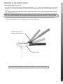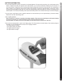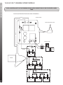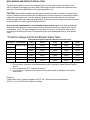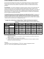
1
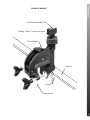
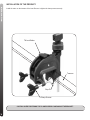
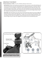
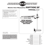
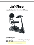
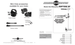
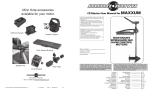
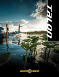
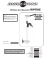
CE Master User Manual for RIPTIDE NOTE: Do not return your Minn Kota motor to your retailer. Your retailer is not authorized to repair or replace this unit. You may obtain service by: • calling Minn Kota at 1-800-227-6433 or 1-507-345-4623; • returning your motor to the Minn Kota Factory Service Center; • sending or taking your motor to any Minn Kota authorized service center on enclosed list. Please include proof of purchase, serial number and purchase date for warranty service with any of the above options. RIPTIDE TRANSOM MOUNT MOTORS serial number purchase date PLEASE THOROUGHLY READ THIS USER MANUAL. FOLLOW ALL INSTRUCTIONS AND HEED ALL SAFETY & CAUTIONARY NOTICES BELOW. USE OF THIS MOTOR IS ONLY PERMITTED FOR PERSONS THAT HAVE READ AND UNDERSTOOD THESE USER INSTRUCTIONS. MINORS MAY USE THIS MOTOR ONLY UNDER ADULT SUPERVISION. Features Installation Cautions Operation Battery Circuit Breaker Wiring Diagram Propeller Replacement Maximizer Maintenance Troubleshooting Warranty pg. 2-3 pg. 4 pg. 5 pg. 6-8 pg. 9-10 pg. 10 pg. 11-12 pg. 13 pg. 13 pg. 13 pg. 13 pg. 14 FEATURES TRAXXIS OVERVIEW Battery Meter Tilt Twist Tiller Extension & 6” Handle 6” / 15mm Maximizer / Permanently Sealed Electronics (On select models) One Hand Stow / Multi-position Mounting Bracket Lifetime Warranty Flexible Composite Shaft Weedless Propeller Permanent Magnet Motor 2 Specifications subject to change without notice. FEATURES TRAXXIS MOUNT Quick Release Depth Collar Steering Tension / Vertical Stow Knob Tilt Lock Button Transom Stop Pin Clamp Screws 3 INSTALLATION INSTALLATION OF THE PRODUCT: Install the motor on the transom of the boat. Be sure to tighten the clamp screws securely. Tilt Lock Button Transom Stop Pin Clamp Screws CAUTION: OVER-TIGHTENING THE CLAMP SCREWS CAN DAMAGE THE BRACKET. 4 CAUTIONS Attention: •Avoid running your motor with the propeller outside of the water. This may result in injuries from the rotating propeller. •It is recommended to set the speed selector to zero and place the motor in the deployed position prior to connecting power cables. Disconnect power cables prior to stowing. •Always ensure that the power cables are not twisted or kinked; and that they are securely routed to avoid a safety or trip hazard. Ensure cables are unobstructed in all locations to avoid damaging the wire insulation. Damage to the insulation could result in failure or injury. •Always inspect the insulation of the power cables prior to use to ensure they are not damaged. •Disregarding these safety precautions may result in an electrical short of the battery(s) and/or motor. Always disconnect the motor from the battery(s) before cleaning or checking the propeller. •Avoid submerging the complete motor as water may enter the lower unit through control head and shaft. Water in the lower unit may cause an electrical short and damage the lower unit. This damage will not be covered by warranty. Caution! •Always operate the motor in a safe distance away from obstructions. Never approach the motor when the propeller is running. Contact with a spinning propeller may endanger you or others. •Always exercise safe practices when using your motor; stay clear of other watercrafts, swimmers, and any floating objects. Always obey water regulations applicable to your area of operation. •Never operate the motor while under the influence of alcohol, drugs, medication, or other substances which may impair your ability to safely operate equipment. •This motor is not suitable for use in strong currents exceeding the thrust level of the motor. The constant noise pressure level of the motor during use is less than 70dB(A). The overall vibration level does not exceed 2,5m/sec≈. 5 OPERATION OPERATION OF THE PRODUCT: Stowing and Deploying Your Motor: There are 2 methods for stowing your motor for travel: Horizontal Stow: Loosen the steering tension knob, grab the back of the motor head or the motor shaft, while lifting up, tilt the motor into the boat (the motor must be lifted approximately 1/2” to disengage locking pins). The bracket will ratchet into a locked position. Be sure to retighten the steering tension knob and slide the quick release depth collar down to the top of the steering tension knob for transport. To deploy your motor from this stowed position, loosen the quick release collar, reposition and retighten to desired depth location, hold the motor shaft or head firmly, and loosen the steering tension knob, press the tilt lock button while holding control head and gently lower the motor into the water. Retighten the quick release collar. Retighten the steering tension knob to the desired steering tension. Vertical Stow: While firmly holding the motor shaft, loosen the steering tension knob and lift up on the motor. Retighten the steering tension knob to retain the vertical stow position of the motor. Be sure to slide the quick release depth collar down to the top of the steering tension knob for added security. To deploy your motor from this vertically stowed position, loosen the quick release collar, hold the motor shaft firmly, and loosen the steering tension knob, and gently lower the motor into the water. Retighten the quick release collar. Retighten the steering tension knob to the desired steering tension. Quick Release Depth Collar Steering Tension / Vertical Stow Knob Tilt Lock Button 6 WARNING : WHEN RAISING OR LOWERING MOTOR, KEEP FINGERS CLEAR OF ALL HINGE AND PIVOT POINTS AND ALL MOVING PARTS. Lift here Tilt and Extension Handle Operation: Your TRAXXIS trolling motor features 7 usable handle tilt positions…45°, 30°, and 15° up and down from the 0° (horizontal) position. To use the down positions, you must first press the release button located on the left underside of the pivot handle. Your TRAXXIS trolling motor handle also features a unique stow position, that is useful for limiting the amount of space required for storage or travel. IMPORTANT: First press the release button located on THE the left underside of the then push the handle downFAILURE until you feel THE MOTOR MUST BE IN OFF POSITION TOpivot USEhandle, TO USE THE STOW POSITION! TO the handle “lock in” IN to THE the stowed position. This will beSTOWING almost parallel the motorWILL shaft.RESULT IN JOINT FAILURE. PUT THE MOTOR OFF POSITION BEFORE THEtoHANDLE OPERATION OPERATION OF THE PRODUCT CONT’D: To extend the handle, pull the handle towards you to the desired position. The handle will extend a full 6 inches. To retract, push the handle in until it meets the face of the motor control head. Handle controls on/off, steering, forward/reverse Release button CAUTION: NEVER OPERATE YOUR MOTOR WHEN IT IS OUT OF THE WATER. 7 OPERATION OPERATION OF THE PRODUCT CONT’D: Steering Tension Adjustment: The steering tension can be adjusted by tightening or loosening the steering tension knob for the desired steering tension. Depth Adjustment The Quick Release Depth Collar can easily be adjusted by opening the lever arm to release to depth collar, sliding it to the desired depth, and then closing the lever arm again. The tension of the quick release depth collar can be adjusted with a screw driver to obtain the proper “feel”. Be careful not to over tighten! Lever Arm Steering Tension / Vertical Stow Knob 8 PINCH POINT WARNING!! BE SURE TO FIRMLY HOLD THE MOTOR SHAFT WHENEVER MAKING ADJUSTMENTS TO THE QUICK RELEASE DEPTH COLLAR, OR TO THE STEERING TENSION ADJUSTMENT KNOB. THE MOTOR CAN SLIDE DOWN QUICKLY AND CAUSE INJURY. The motor will operate with any deep cycle marine 12 volt battery/batteries. For best results use a deep cycle, marine battery with at least a 115 ampere hour rating. As a general on the water estimate, your 12 volt motor will draw one ampere per hour and your 24 volt motor will draw .75 ampere per hour for each pound of thrust produced when the motor is running on high. The actual ampere draw is subject to your particular environmental conditions and operation requirements. Maintain battery at full charge. Proper care will ensure having battery power when you need it, and will significantly improve the battery life. Failure to recharge lead-acid batteries (within 12-24 hours) is the leading cause of premature battery failure. Use a variable rate charger to avoid overcharging. BATTERY BATTERY INFORMATION: If you are using a crank battery to start a gasoline outboard, we recommend that you use a separate deep cycle marine battery/ batteries for your Minn Kota trolling motor. Advice regarding batteries: Never connect the (+) and the (–) terminals of the battery together. Take care that no metal object can fall onto the battery and short the terminals. This would immediately lead to a short and utmost fire danger. Recommendation: Use battery boxes and covered battery terminal clamps like Minn Kota accessory #MK-BC-1. These motors are equipped with a “push to test” battery gauge. The LED provides an accurate display of the remaining charge in the battery. It is only accurate when the motor is off. The gauge reads as: • Four lights indicate full charge. • Three lights indicate good charge. • Two lights indicate low charge. • One light indicates recharge. 9 BATTERY CONNECTION BATTERY CONNECTION 12 Volt Systems: 1.Make sure that the motor is switched off (speed selector on “0”). 2.Connect positive (+) red lead to positive (+) battery terminal. 3. Connect negative (–) black lead to negative (–) battery terminal. 4. For safety reasons do not switch the motor on until the propeller is in the water. 24 Volt Systems: 1. Make sure that the motor is switched off (speed selector on “0”). 2.Two 12 volt batteries are required. 3. The batteries must be wired in series, only as directed in wiring diagram, to provide 24 volts. a. Connect a connector cable to positive ( + ) terminal of battery 1 and to negative ( – ) terminal of battery 2. b.Connect positive (+) red lead to positive (+) terminal on battery 2. c. Connect negative (–) black lead to negative (–) terminal of battery 1. 4.For safety reasons do not switch the motor on until the propeller is in the water. 36 Volt Systems: 1. Make sure that the motor is switched off (speed selector on “0”). 2. Three 12 volt batteries are required. 3. The batteries must be wired in series, only as directed in wiring diagram, to provide 36 volts. a. Connect a connector cable to positive ( + ) terminal of battery 1 and to negative ( – ) terminal of battery 2. b. Connect a connector cable to positive (+) terminal of battery 2 and to negative (–) terminal of battery 3. c. Connect positive (+) red lead to positive (+) terminal on battery 3. d. Connect negative (–) black lead to negative (–) terminal of battery 1. 4.For safety reasons do not switch the motor on until the propeller is in the water. If installing a leadwire plug, observe proper polarity and follow instructions in your boat owner’s manual. See wiring diagram on following pages. • IMPROPER WIRING OF 24/36 VOLT SYSTEM COULD CAUSE BATTERY EXPLOSION! • KEEP LEADWIRE WING NUT CONNECTION TIGHT AND SOLID TO BATTERY TERMINALS. • LOCATE BATTERY IN A VENTILATED COMPARTMENT. CIRCUIT BREAKER Boat Rigging and Motor Installation: An over-current protection device (circuit breaker or fuse) must be used with this motor. Coast Guard requirements dictate that each ungrounded current-carrying conductor must be protected by a manually reset, trip-free circuit breaker or fuse. The type (voltage and current rating) of the fuse or circuit breaker must be sized accordingly to the trolling motor used. The following breaker sizes are recommended guidelines: Maximum thrust Voltage / Recommended circuit breaker rating 30# to 45# 12V 50A @ 12VDC 50# to 55# 12V 60A @ 12VDC 65# to 70# 24V 50A @ 24VDC 80# 24V 60A @ 24VDC 101# 36V 50A @ 36VDC E-Drive 48V 40A @ 48VDC The appropriate wire size needed to connect your trolling motor to the trolling motor batteries varies depending on the length of cable needed and voltage of the motor. For additional information, please consult appropriate ABYC (American Boat and Yacht Council) and Coast Guard requirements. Reference: United States Code of Federal Regulations: 33 CFR 183 – Boats and Associated Equipment ABYC E-11: AC and DC Electrical Systems on Boats 10 THIS IS A UNIVERSAL MULTI-VOLTAGE DIAGRAM. DOUBLE CHECK YOUR MOTORS VOLTAGE FOR PROPER CONNECTIONS Over-Current Protection Devices not shown in illustrations. FIVE SPEED SWITCH INTERRUPTEUR A CING VITESSES WIRING DIAGRAM 12-24 VOLT 5 SPEED MODELS RED M+ RED BLACK BLACK M - WHITE RED B+ YELLOW BLACK M - 12v MOTOR 12V BATT 1 24v 12V BATT 1 12V BATT 2 11 THIS IS A UNIVERSAL MULTI-VOLTAGE DIAGRAM. DOUBLE CHECK YOUR MOTORS VOLTAGE FOR PROPER CONNECTIONS Over-Current Protection Devices not shown in illustrations. CONTROL BOARD BLACK SPEED ADJUSTMENT KNOB RED M+ WIRING DIAGRAM 12-24-36 VOLT VARIABLE SPEED MODELS BATTERY GAUGE RED B+ BLACK B- RED 12v BLACK 12V BATT 1 24v MOTOR 12V BATT 1 12V BATT 2 36v 12V BATT 1 12 12V BATT 2 12V BATT 3 • Disconnect motor from battery prior to changing the propeller. • Hold the propeller and loosen the anode/nut with a wrench. • Remove anode/nut and washer. If the drive pin is sheared/broken, you will need to hold the shaft steady with a screwdriver blade pressed into the slot on the end of the shaft. • Turn the old prop to horizontal (as illustrated) and pull it straight off. If drive pin falls out, push it back in. • Align new propeller with drive pin. • Install prop washer and anode/nut. • Tighten anode/ nut 1/4 turn past snug. [25-35 inch lbs.] Be careful, over tightening can damage prop. CAUTION: DISCONNECT THE MOTOR FROM THE BATTERY BEFORE BEGINNING ANY PROP WORK OR MAINTENANCE. Weedless Propeller Slot End PROPELLER PROPELLER REPLACEMENT: anode/nut Washer Drive pin MAINTENANCE OF THE PRODUCT: 1. After use, these units should be rinsed with fresh water, then wiped down with a cloth dampened with an aqueous based silicone spray such as Armor All®. 2. The propeller must be cleaned of weeds and fishing line. The line can get behind the prop, wear away the seals and allow water to enter the motor. Check this after every 20 hours of operation. 3. Before each use, check to see that the prop nut is secure. 4. To prevent accidental damage during trailering or storage, disconnect the battery whenever the motor is off of 1. 2. • Check battery charge, if low, restore to full charge. 3. Motor is hard to steer: Motor fails to run or lacks power: • Loosen the steering tension knob on the top of bracket. • Check motor for obstructions. The motor may have gone • Lubricate the composite shaft. into current limit. To reset: return to off position, remove 4. Bracket shifts or “walks” on transom: obstruction and resume operation. • With some boats, the transom bracket may loosen or shift • Failure to put the motor in the off position before stowduring heavy use. ing the handle will result in joint failure. 5. You experience prop vibration during normal operation: • Check battery connections for proper polarity. • Remove and rotate the prop 180°. See removal instruc• Make sure terminals are clean and corrosion free. Use tions in prop section. fine sandpaper or emery cloth to clean terminals. NOTE: For all other malfunctions, see enclosed authorized • Check battery water level. Add water if needed. service center listing for nearest service center. Motor looses power after a short running time: TROUBLESHOOTING TROUBLESHOOTING: the water. For prolonged storage, lightly coat all metal parts with an aqueous based silicone spray. 5. For maximum performance, restore battery to full charge before each use. 6. Keep battery terminals clean with fine sandpaper or emery cloth. 7. The weedless wedge propeller is designed to provide absolute weed free operation with very high efficiency. To maintain this top performance, the leading edge of the blades must be kept smooth. If they are rough or nicked from use, restore to smooth by sanding with fine sandpaper. MAINTENANCE The built-In Maximizer’s electronics create pulse width modulation to provide longer running time and extended battery life. With the Maximizer speed control, you may, in some applications, experience interference in your depth finder display. We recommend that you use a separate deep cycle marine battery for your trolling motor and that you power the depth finder from the starting / cranking battery. If problems still persist, call our service department at 1-800-227-6433. MAXIMIZER MAXIMIZER™: (On Select Models) 13 BOAT RIGGING AND PRODUCT INSTALLATION: For safety and compliance reasons, we recommend that you follow American Boat and Yacht Council (ABYC) standards when rigging your boat. Altering boat wiring should be completed by a qualified marine technician. The following specifications are for general guidelines only: CAUTION: These guidelines apply to general rigging to support your Minn Kota Motor. Powering multiple motors or additional electrical devices from the same power circuit may impact the recommended conductor gauge and circuit breaker size. If you are using wire longer than that provided with your unit, follow the conductor gauge and circuit breaker sizing table below. If your total conductor length is more than 50 feet we recommend that you contact a qualified marine technician. An over-current protection device (circuit breaker or fuse) must be used. Coast Guard requirements dictate that each ungrounded current-carrying conductor must be protected by a manually reset, trip-free circuit breaker or fuse. The type (voltage and current rating) of the fuse or circuit breaker must be sized accordingly to the trolling motor used. The table below gives recommended guidelines for circuit breaker sizing. *Conductor Gauge and Circuit Breaker Sizing Table Total Conductor Length (length of all conductors in the total circuit) Motor Thrust 30# 40#, 45# Circuit Breaker 50 Amp @ 12 VDC 50#, 55# 60 Amp @ 12 VDC 70# 50 Amp @ 24 VDC 80# 60 Amp @ 24 VDC 101# 50 Amp @ 36 VDC E-Drive 40 Amp @ 48 VDC 10 feet 20 feet 30 feet 40 feet 50 feet 12 AWG 10 AWG 8 AWG 6 AWG 4 AWG 10 AWG 8 AWG 6 AWG 4 AWG 4 AWG 8 AWG 6 AWG 4 AWG 4 AWG 2 AWG 10 AWG 10 AWG 8 AWG 8 AWG 6 AWG 8 AWG 8 AWG 8 AWG 6 AWG 6 AWG 8 AWG 8 AWG 8 AWG 8 AWG 8 AWG 10 AWG 10 AWG 8 AWG 6 AWG 6 AWG *The conductor and circuit breaker sizing table above is only valid for the following assumptions. 1. No more than 3 conductors are bundled together inside of a sheath or conduit outside of engine spaces. 2. Each conductor has 105oC temp rated insulation. 3. No more than 5% voltage drop allowed at full motor power based on published product power requirements. Reference: United States Code of Federal Regulations: 33 CFR 183 – Boats and Associated Equipment ABYC E-11: AC and DC Electrical Systems on Boats BATEAU GRÉEMENT ET PRODUIT DE L'INSTALLATION : Pour des raisons de sécurité et de conformité, nous recommandons de suivre les normes de l’American Boat And Yacht Council (ABYC) lorsque truquer votre bateau. Modifier le câblage du bateau doit être complété par un technicien marin qualifié. Les spécifications suivantes sont uniquement des directives générales : Avertissement : Ces directives s'appliquent au gréement générale à l'appui de votre moteur Minn Kota. Alimenter plusieurs moteurs ou des dispositifs électriques supplémentaires depuis le même circuit de puissance peut influencer la taille recommandée de la jauge du conducteur et disjoncteur. Si vous utilisez fil plus long que celui fourni avec votre unité, suivre le conducteur jauge et le disjoncteur dimensionnement tableau ci-dessous. Si la longueur totale de votre conducteur est plus de 15 mètres nous recommandons que vous contacter un technicien marin qualifié. Un dispositif de protection de surintensité (disjoncteur ou fusible) doit être utilisé. Les exigences de la Garde-Côte américain disent que chaque conducteur sans fondement de porteurs de courant doit être protégé par un disjoncteur mise en circuit, à déclenchement libre ou un fusible. Le type (tension et courant nominal) du fusible ou disjoncteur doit être dimensionné en conséquence pour le moteur utilisé. Le tableau ci-dessous donne les directives pour le calibrage de disjoncteur. * Jauge de conducteur et disjoncteur Table de dimensionnement Moteur poussée 30# 40#, 45# Longueur totale de chef d'orchestre (longueur de tous les conducteurs dans le circuit total) Disjoncteur Amp 50 @ 12 VDC 50#, 55# Amp 60 @ 12 VDC 70# Amp 50 @ 24 VDC 80# Amp 60 @ 24 VDC 101# Amp 50 @ 36 VDC E-Drive Amp 40 @ 48 VDC 3 mètres 6 mètres 9 mètres 12 mètres 15 mètres 3 mm 5 mm 5 mm 8 mm 13 mm 21 mm 8 mm 13 mm 21 mm 21 mm 8 mm 13 mm 21 mm 21 mm 32 mm 5 mm 5 mm 8 mm 8 mm 13 mm 8 mm 8 mm 8 mm 13 mm 13 mm 8 mm 8 mm 8 mm 8 mm 8 mm 5 mm 5 mm 8 mm 13 mm 13 mm * Le disjoncteur tableau ci-dessus de dimensionnement et chef d'orchestre est uniquement valable pour les hypothèses suivantes. 1. Pas plus de 3 conducteurs sont regroupés à l'intérieur d'une gaine ou conduites à l'extérieur des espaces de moteur. o 2. Chaque conducteur a 105 c temp, évalué à isolation. 3. Pas plus d'une chute de tension de 5 % a permis à la puissance du moteur complet en fonction des besoins de puissance produit publié. Référence : United States Code of Federal Regulations : CFR 33 183 – bateaux et équipement connexe ABYC E-11: AC et DC des systèmes électriques à bord de bateaux REPAIR AND TROUBLESHOOTING We offer several options to help you troubleshoot and/or repair your product. Please read through the options listed below. FREQUENTLY ASKED QUESTIONS Did you know that we have over 100 FAQ’s to help answer all of your Minn Kota questions? Visit www.minnkotamotors.com and click on “Frequently Asked Questions” under the “Service” tab to find an answer to your question. http://www.minnkotamotors.com/service/faq.aspx?linkidentifier=id&itemid=817 AUTHORIZED SERVICE CENTERS Minn Kota has over 300 authorized service centers in the United States and Canada where you can purchase parts or get your products repaired. Please visit www.minnkotamotors.com and click on “Service Center Locator” under the “Service” tab to locate a service center in your area. http://www.minnkotamotors.com/service/asclocator.aspx CALL US (FOR U.S. AND CANADA) Our customer service representatives are available Monday – Friday between 7:00am – 4:30pm CST at 800-227-6433. If you are calling to order parts, please have the 11-character serial number from your product, specific part numbers, and credit card information available. This will help expedite your call and allow us to provide you with the best customer service possible. You can reference the parts list located in your manual to identify the specific part numbers. EMAIL US You can email our customer service department with questions regarding your Minn Kota products. To email your quesiton, visit www.minnkotamotors.com and click on “Contact Us” under the “Service” tab. http://www.minnkotamotors.com/service/contact.aspx RT80/T This page provides MinnKota® WEEE compliance disassembly instructions. For more information about where you should dispose of your waste equipment for recycling and recovery and/or your European Union member state requirements, please contact your dealer or distributor from which your product was purchased. Tools required: Flat Head screw driver, Phillips screw driver, Socket set, Pliers. 80 LBS THRUST 24 VOLT 42” SHAFT 200 208 205 210 210 215 220 390 225 230 395 400 420 380 385 235 370 375 365 240 415 360 405 410 245 250 260 255 135 265 136 270 425 275 315 280 320 285 325 316 290 330 295 300 335 345 305 355 317 345 350 356 310 340 70 115 20 50 65 60 30 85 120 110 35 1010 40 10 15 100 1015 1020 25 5 80 90 95 1 PARTS LIST 1000 P/N 2316228 2-100-214 140-010 788-040 2-200-397 2-300-340 421-376 144-017 880-025 188-094 9-738-004 975-041 701-043 701-009 830-027 830-094 990-051 990-052 973-025 992-010 992-045 640-018 640-123 2889460 200 2195659 205 2060296 208 2325666 210 2074081 215 2043427 220 2184017 n2888411 225 2303434 230 2062503 235 2062905 240 2303412 245 2263434 250 2383406 255 2061517 260 2333101 265 2991521 1 5 10 15 20 25 30 35 40 50 60 65 70 80 85 90 95 100 110 115 120 135 136 n Item Decal, c-box cover C-box cover Decal - MinnKota Battery meter, 24v SW Screw, #8 x 7/8 SS Control board, 24/36V Potentiometer Replacement Kit Screw, #8-30 x 5/8 SS Control box, VARS, SW Strain relief Screw, #6 x 5/8 SS Screw, #8 x 1 SS Screw, #10-24 x 2 PPH SS Collar, c-box Nut, 10-24, nylock, SS Cam lock/depth collar assy 24V Motor 42” SW Armature assembly Bearing Retaining ring Center housing assemby Brush end housing assembly Plain end housing assembly STD Flange bearing Seal Brush Brush plate assembly Brush spring O-ring, motor O-ring, thru-bolt Screw, 10-32 x 2 Thru-bolt Washer, steel Washer, nylatron Spacer, brush plate Washer, Belleville Spacer, thrust Leadwire, black Leadwire, red Seal and O-ring Kit Description 2 1 1 6 2 1 1 1 1 1 1 2 1 2 1 1 1 1 1 1 1 1 1 2 2 1 2 2 2 2 2 2 2 2 2 1 1 1 Qty 1 1 1 Item P/N n 1378132 n 2994876 1000 2331160 1010 2262658 1015 2091701 1020 2198401 Propeller kit WW2 Propeller bag assy Propeller WW2 Drive pin, large Washer, prop, large Nut, nylock, prop, Anode Description * This item is part of an assembly. This item cannot be sold separately due to machining and /or assembly that is required. Spring, handle pivot Washer, pot holder Leadwire assy, includes [235] 2062715 2061700 2992523 415 420 425 1 1 2 1 1 1 2 1 1 1 1 6 Handle assy, VARS [360-410] Grip/handle assy, VARS [360-375] Bearing, handle Screw, #6 PFH SS Yoke / spider assy, VARS Spring, detent, off Bearing, handle pivot Handle pivot, top Spring, release button Button, release Handle pivot, bottom Screw, #6 x 5/8 SS 2990957 2990456 2060015 2063405 2884092 2302742 2060005 2060900 2302745 2063700 2060905 2303412 Qty n 360 365 370 375 380 385 390 395 400 405 410 Description Bracket assy, Aluminum [270-356] 1 Knob, steering tension, soft 1 Collet 1 Lock arm 1 Spring, lock arm 1 Hinge 1 Pin, lock, ss 1 Pin, lock, ss 1 Bushing, hinge 1 Tube 42” 1 Bolt 1/4-20 x 2 3/8”, ss 3 Screw-clamp 2 Washer-clamp screw 2 Bracket, right, SW 1 Cam deactivator 1 Bushing, dowel 1/4 x 1/2 3 Spring, cam deactivator 1 Clamp screw kit 2 per kit Handle, clamp 2 Roll pin 2 Bracket, left, SW 1 Nut, 1/4-20, nylock, ss 3 Pin, stop 1 P/N 2991798 2060100 2068400 2064200 2062701 2061821 2062603 2062603 2037301 2002012 2063501 2061301 2331700 2771949 2067905 2067306 2062702 2771303 2050925 2052625 2771948 2263103 2062604 n 270 275 280 285 290 295 300 305 310 315 316 317 320 325 330 335 n 340 345 350 355 356 Item 1 1 1 1 Item P/N P/N 2094917 REV. K ECN 33752 Qty 2-12 Description Qty In the U.S.A., replacement parts may be ordered directly from MINN KOTA Parts Dept., 121 Power Drive,P.O. Box 8129 Mankato, Minnesota 56002-8129. In Canada, parts may be ordered from any of the Fuera de los Estados Unidos, consultar la lista anexa para ubicar el Centro de servicio autorizado Canadian Authorized Service Centers shown on the enclosed list. Be sure to provide the model and serial numbers of your motor when ordering parts. Please use the correct part numbers from the parts MINN KOTA. No dejar de incluir el número del MODELO y el número de SERIE del motor para el cual se solicitan las piezas. Usar siempre los números de pieza correctos indicados en la lista de piezas. list. Payment for any parts ordered from the MINN KOTA parts department, may be by cash, personal check, Discover Card, MasterCard or VISA. To order, call 1-800-227-6433 or FAX 1-800-527-4464. ENVIRONMENTAL COMPLIANCE STATEMENT: It is the intention of Johnson Outdoors Marine Electronics, Inc. to be a responsible corporate citizen, operating in compliance with known and applicable environmental regulations, and a good neighbor in the communities where we make or sell our products. WEEE Directive: EU Directive 2002/96/EC “Waste of Electrical and Electronic Equipment Directive (WEEE)” impacts most distributors, sellers, and manufacturers of consumer electronics in the European Union. The WEEE Directive requires the producer of consumer electronics to take responsibility for the management of waste from their products to achieve environmentally responsible disposal during the product life cycle. WEEE compliance may not be required in your location for electrical & electronic equipment (EEE), nor may it be required for EEE designed and intended as fixed or temporary installation in transportation vehicles such as automobiles, aircraft, and boats. In some European Union member states, these vehicles are considered outside of the scope of the Directive, and EEE for those applications can be considered excluded from the WEEE Directive requirement. This symbol (WEEE wheelie bin) on product indicates the product must not be disposed of with other household refuse. It must be disposed of and collected for recycling and recovery of waste EEE. Johnson Outdoors Marine Electronics, Inc. will mark all EEE products in accordance with the WEEE Directive. It is our goal to comply in the collection, treatment, recovery, and environmentally sound disposal of those products; however, these requirement do vary within European Union member states. For more information about where you should dispose of your waste equipment for recycling and recovery and/or your European Union member state requirements, please contact your dealer or distributor from which your product was purchased. Disposal: Minn Kota motors are not subject to the disposal regulations EAG-VO (electric devices directive) that implements the WEEE directive. Nevertheless never dispose of your Minn Kota motor in a garbage bin but at the proper place of collection of your local town council. Never dispose of battery in a garbage bin. Comply with the disposal directions of the manufacturer or his representative and dispose of them at the proper place of collection of your local town council. LIMITED WARRANTY LIMITED LIFETIME WARRANTY ON COMPOSITE SHAFT, LIMITED TWO-YEAR WARRANTY ON ENTIRE PRODUCT: Composite Shaft Johnson Outdoors Marine Electronics, Inc. warrants to the original purchaser that the composite shaft of the purchaser’s Minn Kota® trolling motor is free from defects in materials and workmanship appearing within the original purchaser’s lifetime. Johnson Outdoors Marine Electronics, Inc. will provide a new shaft, free of charge, to replace any composite shaft found to be defective more than two (2) years after the date of purchase. Providing such a new shaft shall be the sole and exclusive liability of Johnson Outdoors Marine Electronics, Inc. and the sole and exclusive remedy of the purchaser for breach of this warranty; and purchaser shall be responsible for installing, or for the cost of labor to install, any new composite shaft provided by Johnson Outdoors Inc. Entire Product Johnson Outdoors Marine Electronics, Inc. warrants to the original purchaser that the purchaser’s entire Minn Kota® trolling motor is free from defects in materials and workmanship appearing within two (2) years after the date of purchase. Johnson Outdoors Marine Electronics, Inc. will, at its option, either repair or replace, free of charge, any parts, including any composite shaft, found to be defective during the term of this warranty. Such repair or replacement shall be the sole and exclusive liability of Johnson Outdoors Marine Electronics, Inc. and the sole and exclusive remedy of the purchaser for breach of this warranty. Terms Applicable to Both Warranties These limited warranties do not apply to motors used commercially nor do they cover normal wear and tear, blemishes that do not affect the operation of the motor, or damage caused by accidents, abuse, alteration, modification, misuse or improper care or maintenance. DAMAGE TO MOTORS CAUSED BY THE USE OF REPLACEMENT PROPELLERS OR OTHER REPLACEMENT PARTS NOT MEETING THE DESIGN SPECIFICATIONS OF THE ORIGINAL PROPELLER AND PARTS WILL NOT BE COVERED BY THIS LIMITED WARRANTY. The cost of normal maintenance or replacement parts which are not defective are the responsibility of the purchaser. To obtain warranty service in the U.S., the motor or part believed to be defective, and proof of original purchase (including the date of purchase), must be presented to a Minn Kota® Authorized Service Center or to Minn Kota®’s factory service center in Mankato, MN. Any charges incurred for service calls, transportation or shipping/freight to/from the Minn Kota® Authorized Service Center or factory, labor to haul out, remove, re-install or re-rig products removed for warranty service, or any other similar items are the sole and exclusive responsibility of the purchaser. Motors purchased outside of the U.S. must be returned prepaid with proof of purchase (including the date of purchase and serial number) to any Authorized Minn Kota® Service Center in the country of purchase. Warranty service can be arranged by contacting a Minn Kota® Authorized Service Center listed on the enclosed sheet, or by contacting the factory at 1-800-2276433 or fax 1-800-527-4464. Note: Do not return your Minn Kota® motor to your retailer. Your retailer is not authorized to repair or replace them. THERE ARE NO EXPRESS WARRANTIES OTHER THAN THESE LIMITED WARRANTIES. IN NO EVENT SHALL ANY IMPLIED WARRANTIES (EXCEPT ON THE COMPOSITE SHAFT), INCLUDING ANY IMPLIED WARRANTIES OF MERCHANTABILITY OR FITNESS FOR PARTICULAR PURPOSE, EXTEND BEYOND TWO YEARS FROM THE DATE OF PURCHASE. IN NO EVENT SHALL JOHNSON OUTDOORS MARINE ELCTRONCIS, INC. BE LIABLE FOR INCIDENTAL, CONSEQUENTIAL OR SPECIAL DAMAGES. Some states do not allow limitations on how long an implied warranty lasts or the exclusion or limitation of incidental or consequential damages, so the above limitations and/or exclusions may not apply to you. This warranty gives you specific legal rights and you may also have other legal rights which vary from state to state. “WARNING: This product contains chemical(s) known to the state of California to cause cancer and/or reproductive toxicity.” 14 Minn Kota accessories available for your motor. Power Center Portable Chargers Quick Plugs Extension Handles Visit our website at www.minnkotamotors.com © 2010 Johnson Outdoors Marine Electronics, Inc. p/n 2097124 REV. G ECN 33016 3-11