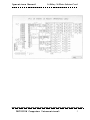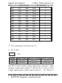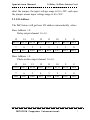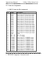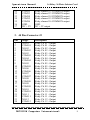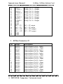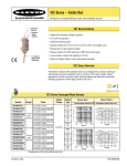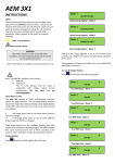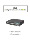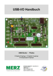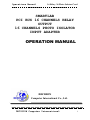
1
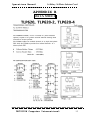
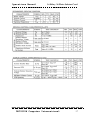
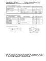
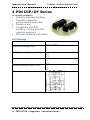
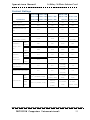
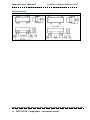
Operations Manual 16 Relay /16 Photo Isolator Card SMARTLAB PCI BUS 16 CHANNELS RELAY OUTPUT 16 CHANNELS PHOTO ISOLATOR INPUT ADAPTER OPERATION MANUAL DECISION Computer International Co., Ltd. DECISION Computer International i Operations Manual 16 Relay /16 Photo Isolator Card CHAPTERS 1. Introduction………………….………………..…… 2. Hardware Configuration……………………..…….. 1 4 APPENDICES A. Warranty Information …………………………..…. 11 B. Data Sheet………………………………….………. 14 ii DECISION Computer International Operations Manual 16 Relay /16 Photo Isolator Card CHAPTER 1 INTRODUCTION The PCI 16 channels relay output / photo isolator input adapter is a 32 bits PCI bus board with Plug and Play (PnP) features, it is a programmable I/O interface card for PC/486, Pentium, or compatibles. The PnP features let hardware configuration for IRQ and I/O address is detected by BIOS automatically, you don’t need set switch and jumper. The PCI 16 channels relay output / photo isolator input adapter provides relay output functions. The relay output part provides 16 relays to drive 16 different output channels. Each relay channel can be used to control ON/ OFF of external devices, to drive external power relays, to activate alarms… etc. The photo isolator input part provides 16 photo couple digital input channels, which allow the input signals to be completely floated and prevent the ground loop. The features of PCI 16 channels relay output / 16 channels photo isolator input adapter are: 32 bits PCI bus with Plug and Play (PnP) features. Support 16 relay output channels and 16 photo couple input channels. Max contact rating for relay: 70V/AC, 100V/DC 0.25AMP. Response time for relay: 1 ms minimum. Contact resistance for relay: 0.2 OHM maximum. Support several operating modes that are programmable. DECISION Computer International 1 Operations Manual 16 Relay /16 Photo Isolator Card Activation voltage: When short jumpers (input range from 0 to 20V) 0 to 1.5V inactive 3 to 20V active When open jumpers (input range from 0 to 30V) 0 to 16.6V inactive 18 to 30V active PACKAGE CONTENTS: 2 SMARTLAB PCI bus 16 channels relay output / 16 channels photo couple input adapter. User’s manual. Warranty form. DECISION Computer International Operations Manual 16 Relay /16 Photo Isolator Card DECISION Computer International 3 Operations Manual 16 Relay /16 Photo Isolator Card CHAPTER 2 HARDWARE CONFIGURATION Before you use the PCI 16 channels relay output / 16 channels photo couple input adapter, Please check our technical web site http://www.smatlab.com. Observe the figure in the follows, the proper settings for the PCI 16 channels relay output / 16 channels photo couple input adapter is described in the following. 4 DECISION Computer International Operations Manual 16 Relay /16 Photo Isolator Card 2.1 Switch and Jumper Settings 1. Card ID setting The switch is used to identify card number, default setting is card 15, and there are two methods to set the card number: a. PnP mode Just plug in SMARTLAB PCI BUS 16 CHANNELS RELAY OUTPUT / 16 CHANNELS PHOTO ISOLATOR INPUT ADAPTER into PCI slot, the PCI BIOS will allocate I/O address to each adapter automatically and assign card number start from 0 to each adapter. You may set any card number at PnP mode, and you need use software tools to distinguish port id. Almost all of the operating systems run at PnP mode. b. manual mode Set card number by card identifier switch, the PCI BIOS will assign pre-allocated I/O address to each adapter. Please set different card number to each adapter (do not duplicate card number setting). 1 2 3 4 OFF OFF OFF OFF Card Number 15 ON OFF OFF OFF 14 OFF ON OFF OFF 13 DECISION Computer International 5 Operations Manual 16 Relay /16 Photo Isolator Card ON ON OFF OFF 12 OFF OFF ON OFF 11 ON OFF ON OFF 10 OFF ON ON OFF 9 ON ON ON OFF 8 OFF OFF OFF ON 7 ON OFF OFF ON 6 OFF ON OFF ON 5 ON ON OFF ON 4 OFF OFF ON ON 3 ON OFF ON ON 2 OFF ON ON ON 1 ON ON ON ON 0 The card number starts from 0 to 15. 2. JP1 to JP16 . . JP1 Jumper Input Range Inactive Voltage Active Voltage Open 0 to 30V 0 to 1.5V 3 to 20V Short 0 to 20V 0 to 16.5V 18 to 30V The JP1 is used to select voltage signal opto+ and opto- range of photo couple input channel 1, and the JP2 is used to select voltage signal range of photo input channel 2, …etc. When we 6 DECISION Computer International Operations Manual 16 Relay /16 Photo Isolator Card short the jumper, the input voltage range is 0 to 20V, and open the jumper means input voltage range is 0 to 30V. 2.2 I/O Address The PnP feature will get base I/O address automatically, where Base Address + 0: Relay output channel 1 to 16 15 14 13 12 11 10 9 RL16 RL15 RL14 RL13 RL12 RL11 RL10 8 RL9 7 RL8 6 RL7 5 RL6 4 RL5 3 RL4 2 RL3 1 RL2 0 RL1 Base Address + 0: Photo isolator input channel 1 to 16. 15 IN16 14 IN15 13 IN14 12 IN13 11 IN12 10 IN11 9 IN10 8 IN9 7 IN8 6 IN7 5 IN6 4 IN5 3 IN4 2 IN3 1 IN2 0 IN1 DECISION Computer International 7 Operations Manual 16 Relay /16 Photo Isolator Card 2.3 Connector Assignments 1. DB 37 Connector Pin Assignments Pin 1 2 3 4 5 6 7 8 9 10 11 12 13 14 15 16 17 18 19 20 21 22 23 24 25 26 27 28 29 30 8 Single NO01 NO02 NO03 NO04 NO05 NO06 NO07 NO08 NO09 NO10 NO11 NO12 NO13 NO14 NO15 NO16 GND DC + 5V DC +12V COM01 COM02 COM03 COM04 COM05 COM06 COM07 COM08 COM09 COM10 COM11 Description Relay channel 1, Normal open output Relay channel 2, Normal open output Relay channel 3 Normal open output Relay channel 4 Normal open output Relay channel 5 Normal open output Relay channel 6 Normal open output Relay channel 7 Normal open output Relay channel 8 Normal open output Relay channel 9 Normal open output Relay channel 10 Normal open output Relay channel 11 Normal open output Relay channel 12 Normal open output Relay channel 13 Normal open output Relay channel 14 Normal open output Relay channel 15 Normal open output Relay channel 16 Normal open output GND DC + 5V output DC +12V output Relay channel 1, COMMON output Relay channel 2, COMMON output Relay channel 3, COMMON output Relay channel 4, COMMON output Relay channel 5, COMMON output Relay channel 6, COMMON output Relay channel 7, COMMON output Relay channel 8, COMMON output Relay channel 9, COMMON output Relay channel 10 COMMON output Relay channel 11 COMMON output DECISION Computer International Operations Manual 31 32 33 34 35 36 37 COM12 COM13 COM14 COM15 COM16 GND DC + 5V 16 Relay /16 Photo Isolator Card Relay channel 12 COMMON output Relay channel 13 COMMON output Relay channel 14 COMMON output Relay channel 15 COMMON output Relay channel 16 COMMON output GND DC + 5V output 2. 40 Pins Connector J2 Pin 1 2 3 4 5 6 7 8 9 10 11 12 13 14 15 16 17 18 19 20 21 22 23 24 Single NO-01 COM-01 NO-02 COM-02 NO-03 COM-03 NO-04 COM-04 NO-05 COM-05 NO-06 COM-06 NO-07 COM-07 NO-08 COM-08 NO-09 COM-09 NO-10 COM-10 NO-11 COM-11 NO-12 COM-12 Description Relay Ch. 01 - Output Relay Ch. 01 - Output Relay Ch. 02 - Output Relay Ch. 02 - Output Relay Ch. 03 - Output Relay Ch. 03 - Output Relay Ch. 04 - Output Relay Ch. 04 - Output Relay Ch. 05 - Output Relay Ch. 05 - Output Relay Ch. 06 - Output Relay Ch. 06 - Output Relay Ch. 07 - Output Relay Ch. 07 - Output Relay Ch. 08 - Output Relay Ch. 08 - Output Relay Ch. 09 - Output Relay Ch. 09 - Output Relay Ch. 10 - Output Relay Ch. 10 - Output Relay Ch. 11 - Output Relay Ch. 11 - Output Relay Ch. 12 - Output Relay Ch. 12 - Output DECISION Computer International 9 Operations Manual 25 26 27 28 29 30 31 32 33 34 35 36 37 38 39 40 NO-13 COM-13 NO-14 COM-14 NO-15 COM-15 NO-16 COM-16 GND GND DC + 5V DC + 5V DC + 12V DC + 12V GND GND 16 Relay /16 Photo Isolator Card Relay Ch. 13 - Output Relay Ch. 13 - Output Relay Ch. 14 - Output Relay Ch. 14 - Output Relay Ch. 15 - Output Relay Ch. 15 - Output Relay Ch. 16 - Output Relay Ch. 16 - Output DC + 5V output DC + 5V output DC + 12V output DC + 12V output 3. 40 Pins Connector J3 Pin 1 2 3 4 5 6 7 8 9 10 11 12 13 14 15 Single IN-01IN-01+ IN-02IN02+ IN-03IN-03+ IN-04IN-04+ IN-05IN-05+ IN-06IN-06+ IN-07IN-07+ IN-08- Description Opto-isolator Ch. 01 - Input Opto-isolator Ch. 01 + Input Opto-isolator Ch. 02 - Input Opto-isolator Ch. 02 + Input Opto-isolator Ch. 03 - Input Opto-isolator Ch. 03 + Input Opto-isolator Ch. 04 - Input Opto-isolator Ch. 04 + Input Opto-isolator Ch. 05 - Input Opto-isolator Ch. 05 + Input Opto-isolator Ch. 06 - Input Opto-isolator Ch. 06 + Input Opto-isolator Ch. 07 - Input Opto-isolator Ch. 07 + Input Opto-isolator Ch. 08 - Input 10 DECISION Computer International Operations Manual 16 17 18 19 20 21 22 23 24 25 26 27 28 29 30 31 32 33 34 35 36 37 38 39 40 IN-08+ IN-09IN-09+ IN-10IN-10+ IN-11IN-11+ IN-12IN-12+ IN-13IN-13+ IN-14IN-14+ IN-15IN-15+ IN-16IN-16+ GND GND DC + 5V DC + 5V DC + 12V DC + 12V GND GND 16 Relay /16 Photo Isolator Card Opto-isolator Ch. 08 + Input Opto-isolator Ch. 09 - Input Opto-isolator Ch. 09 + Input Opto-isolator Ch. 10 - Input Opto-isolator Ch. 10 + Input Opto-isolator Ch. 11 - Input Opto-isolator Ch. 11 + Input Opto-isolator Ch. 12 - Input Opto-isolator Ch. 12 + Input Opto-isolator Ch. 13 - Input Opto-isolator Ch. 13 + Input Opto-isolator Ch. 14 - Input Opto-isolator Ch. 14+ Input Opto-isolator Ch. 15 - Input Opto-isolator Ch. 15 + Input Opto-isolator Ch. 16 - Input Opto-isolator Ch. 16 + Input DC + 5V output DC + 5V output DC + 12V output DC + 12V output DECISION Computer International 11 Operations Manual 16 Relay /16 Photo Isolator Card APPENDIX A WARRANTY INFORMATION A.1 Copyright Copyright DECISION COMPUTER INTERNATIONAL CO., LTD. All rights reserved. No part of SmartLab software and manual may be produced, transmitted, transcribed, or translated into any language or computer language, in any form or by any means, electronic, mechanical, magnetic, optical, chemical, manual, or otherwise, without the prior written permission of DECISION COMPUTER INTERNATIONAL CO., LTD. Each piece of SmartLab package permits user to use SmartLab only on a single computer, a registered user may use he program on a different computer, but may not use the program on more than one computer at the same time. Corporate licensing agreements allow duplication and distribution of specific number of copies within the licensed institution. Duplication of multiple copies is not allowed except through execution of a licensing agreement. Welcome call for details. 12 DECISION Computer International Operations Manual 16 Relay /16 Photo Isolator Card A.2 Warranty Information SmartLab warrants that for a period of one year from the date of purchase (unless otherwise specified in the warranty card) that the goods supplied will perform according to the specifications defined in the user manual. Furthermore that the SmartLab product will be supplied free from defects in materials and workmanship and be fully functional under normal usage. In the event of the failure of a SmartLab product within the specified warranty period, SmartLab will, at its option, replace or repair the item at no additional charge. This limited warranty does not cover damage resulting from incorrect use, electrical interference, accident, or modification of the product. All goods returned for warranty repair must have the serial number intact. Goods without serial numbers attached will not be covered by the warranty. The purchaser must pay transportation costs for goods returned. Repaired goods will be dispatched at the expense of SmartLab. To ensure that your SmartLab product is covered by the warranty provisions, it is necessary that you return the Warranty card. Under this Limited Warranty, SmartLab's obligations will be limited to repair or replacement only, of goods found to be defective a specified above during the warranty period. SmartLab is not liable to the purchaser for any damages or losses of any kind, through the use of, or inability to use, the SmartLab product. DECISION Computer International 13 Operations Manual 16 Relay /16 Photo Isolator Card SmartLab reserves the right to determine what warranty repair or replacement. constitutes Return Authorization: It is necessary that any returned goods are clearly marked with an RA number that has been issued by SmartLab. Goods returned without this authorization will not be attended to. 14 DECISION Computer International Operations Manual 16 Relay /16 Photo Isolator Card APPENDIX B DATA SHEET DECISION Computer International 15 Operations Manual 16 Relay /16 Photo Isolator Card 16 DECISION Computer International Operations Manual 16 Relay /16 Photo Isolator Card DECISION Computer International 17 Operations Manual 16 Relay /16 Photo Isolator Card 18 DECISION Computer International Operations Manual 16 Relay /16 Photo Isolator Card DECISION Computer International 19 Operations Manual 16 Relay /16 Photo Isolator Card 20 DECISION Computer International Operations Manual 16 Relay /16 Photo Isolator Card DECISION Computer International 21 Operations Manual 16 Relay /16 Photo Isolator Card 22 DECISION Computer International Operations Manual 16 Relay /16 Photo Isolator Card DECISION Computer International 23 Operations Manual 16 Relay /16 Photo Isolator Card 4 PIN DIP/DF Series UL models available Industry standard package Transfer molded for environmental protection Miniature size Compatible with DIP handling, sorting and PCB insertion quipment Optional shielding and diodes Coil Ratings Part Number Nominal Voltage (VDC) Coil Resistance (ohms) ±10% Operate Voltage (VDC) max. Release Voltage (VDC) min. DB1A**BW(D) DA1A**BW(D) 5 12 24 500 850 2200 3.8 9.0 18.0 0.5 1.0 2.0 Schematics 24 DECISION Computer International Operations Manual 16 Relay /16 Photo Isolator Card Contact Ratings DA1A**BW DB1A**BW Parameters Power (W) max. Voltage (VDC) max. Switching Current (A) max. Carry Current (A) max. Contact Resistance (ohms) max. (initial) Open Breakdown Contact DA1A**NW DA2A**BW DB2A**BW DA1C**BW DA1A**DW DF1A**BW DA1B**BW DB1B**BW DB1C**BW Mercury DF1B**BW 10 3 50 10 200 100 500 200 0.5 0.25 2.0 0.5 1.0 0.5 2.0 1.0 0.15 0.15 0.1 250 200 1000 250 1500 1500 1500 1500 1010 108 1010 1010 1010 1010 1010 1010 1.0 2.0 0.5 2.5 0.15 (1A) 0.2 (1B) Voltage (VDC) Contact min. to Coil Open Insulation Contact Resistance (ohms) min. Contact to Coil Operate Time (mS) max (incl. bounce) Release Time (mS) max. Low Level 108 (10mVDC, 10µA) Electrical Life Rated Load 2.0 (DW) 1.0 (NW) 2.0 (DW) 1.0 0.5 5 X 10⁸ 109 (10VDC, 108 (10mVDC, (10VDC, 4mA) 4mA) 10µA) 2 X 10 6 X 10⁵ (20VDC, 0.5A) 1.0 (NW) 6 (12VDC, 106 (50VDC, 6 X 10⁵ 1.0A) (20VDC, 0.5A) 0.25A) DECISION Computer International 25 Operations Manual 16 Relay /16 Photo Isolator Card Dimensions DA - DB Series DF Series 26 DECISION Computer International