1
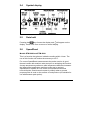
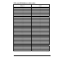
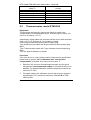
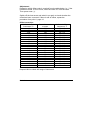
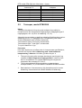
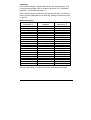
User Manual/Bruger manual ETM 2000 Series Digital thermometers/digitale termometre Copyright 2000 AMETEK DENMARK A/S 105766 02 17-12-2002 ............................................................ENGLISH ............................................................... DANSK 17-12-2002 105766 02 List of contents 1.0 2.0 Introduction ..............................................................................2 Operating the instrument ........................................................3 2.1 Switch on/Switch off...................................................................... 3 2.2 Probe connection.......................................................................... 3 2.3 Backlight ....................................................................................... 3 2.4 Symbol display.............................................................................. 4 2.5 Data hold....................................................................................... 4 2.6 SpeedRead ................................................................................... 4 2.7 Differential input............................................................................ 5 2.8 Celsius/Fahrenheit selection ........................................................ 5 2.9 Manual selection of display resolution.......................................... 6 2.10 Selection of thermocouple ............................................................ 6 2.11 MAX/MIN function ......................................................................... 6 2.11.1 Error indications regarding sensor................................... 7 3.0 Data logging..............................................................................8 3.1 3.2 3.3 3.4 3.5 3.6 3.7 4.0 Setting internal clock..................................................................... 8 Manual logging ............................................................................. 9 Preset interval logging .................................................................. 9 Output of stored data on instrument display............................... 10 Output stored data to DigiLog and PC software......................... 10 Transmission of stored data to a printer or terminal emulator.... 10 Erasing of stored data................................................................. 11 Electrical specifications ........................................................12 4.1 ETM-2000, ETM-2029, and ETM-2098 ...................................... 12 4.2 ETM-2024 and ETM-2084 .......................................................... 12 4.3 Batteries...................................................................................... 13 5.0 Adjustment and calibration procedures ..............................14 5.1 RTD Pt100, ETM-2084 ............................................................... 14 5.1.1 Zero offset calibration procedure ................................... 15 5.2 Thermocouples, model ETM-2098 ............................................. 18 5.2.1 Calibration mode............................................................ 19 5.2.2 Calibration with ”cold junction compensation” activated 21 5.2.3 Zero offset calibration procedure ................................... 21 6.0 Warranty..................................................................................23 1/23 ENGLISH 1.0 Introduction These operating instructions cover all models in the ETM 2000 Series. Therefore, some of the options described may not apply to this instrument. Please check the functions of the instrument you have purchased before proceeding. If in doubt, the type designation will appear on the display when the instrument is switched on. Table of functions Model ETM 2000 Sensor type K ETM 2024 ETM 2029 ETM 2084 ETM 2098 PT100 K,T,J,N,R ,S PT100 K,T,J,R,N ,S 2 input Yes SpeedRead Yes Yes * Yes Yes Yes Yes Yes Yes Yes Yes Yes Range lock Yes Yes Yes Yes MAX/MIN Yes Yes Yes Yes IP 67 IP 65 IP 67 IP 65 Yes Yes C°/F° Data Hold Density IP 65 Logging function * Yes The instrument is delivered with °C readout. Refer to rear of instrument for the temperature ranges. Batteries Two type AA batteries (Penlight) included. Follow instructions on reverse of instrument for fitting/replacement. When symbol appears on display, replace batteries. Serial No. The S/N of the ETM instruments is placed under the batteries. This will secure that the number is not being removed by accident or by wear and tear. ENGLISH 2/23 2.0 Operating the instrument 2.1 Switch on/Switch off Press key for on and key for off. The instrument will automatically switch off after 12 min. unless any key is activated or the instrument is in LOG MAX/MIN mode. If key is held when unit is switched on, automatic switch off function will be disabled until the unit is switched off. Display shows ∧ and ∨. 2.2 Probe connection Warning Do not bring the probe into contact with any service connected to a hazardous voltage (i.e. a voltage exceeding 30 volts RMS or 42.5 volts peak with respect to either earth or ground). Ensure that the probe is suitable for the application, paying particular attention to the temperature range and type of thermocouple. Connect probe plug into the socket at top of instrument ensuring correct polarity. Please note that temperature information on probes is typically the specification of the sensor element. Very often a plastic handle or similar is mounted on the sensor. Such handles cannot stand the often very high temperatures. 2.3 Backlight Press and hold held. key. The light will be on as long as the key is 3/23 ENGLISH 2.4 Symbol display 2.5 Data hold Pressing the key freezes the display and will appear on the display. Press once more to return to normal display. 2.6 SpeedRead Models ETM-2029 and ETM-2098. This is a function that gives an indicative reading within 14 sec. The use of this function will reduce the accuracy to ±2°C. For correct SpeedRead measurements the probe must be in good thermal contact with medium under test prior to activating the function. A steep temperature gradient or wide temperature difference between the initial probe temperature and item under test is required. SpeedRead is suitable for core frozen food measurements and hot/cold liquids. Good thermal contact is unlikely when a general purpose probe is used on the surface of food produce (not suitable for use with between pack probe). ENGLISH 4/23 Insert probe and press key. The symbol will appear and the display will flash FAST until the correct reading appears and the will be displayed. This reading will automatically be held. Press key to return to normal mode. If it is not possible to obtain a faster reading due to the similarity of probe tip temperature and temperature of item to be measured then the symbol will be cancelled and the instrument will return to normal mode. 2.7 Differential input Model ETM-2098. The thermometer can be set to read input A, B or A-B, which will result in readout of the difference between input A and input B (A minus B). Input is selected by pressing the key. The channel selected will be shown on the display, and recalled, when the instrument is next powered up. NOTE: The channel selection will not operate if the display is in HOLD, MAX/MIN or LOG mode. These will be shown as or in the symbol display. 2.8 , Celsius/Fahrenheit selection Models ETM-2024, ETM-2029, ETM-2084 and ETM-2098. key. The Select the desired temperature scale by pressing selected scale is confirmed by °C or °F in the symbol display and is retained when the instrument is switched off. NOTE: Celsius/Fahrenheit selection is not possible, if one of the functions HOLD, MAX/MIN or LOG has been selected. 5/23 ENGLISH These are indicated in the display as symbol display. , or in the Model ETM-2000 always shows °C. 2.9 Manual selection of display resolution Models ETM-2024, ETM-2029, ETM-2084 and ETM-2098. All instruments have a 0.1° resolution in the range from –199.0° to +199.9° and a 1° resolution outside this range. To fix the display to a 1° resolution in the entire measuring range, press the key. A/R will now disappear from the symbol display. To cancel the mode press the key again and A/R will be shown on the symbol display again. 2.10 Selection of thermocouple Models ETM-2029 and ETM-2098. key to select type K, T, J, N, R or S thermocouple. Press the This selection is retained when the instrument is switched off. 2.11 MAX/MIN function Models ETM-2024, ETM-2029, ETM-2084 and ETM-2098. key to start. The instrument will display alternating ∧ Press the and ∨ symbols and current reading. Press again to display MAX temperature reading and the ∧ symbol will be displayed. Press again to display MIN temperature reading and the ∨ symbol will be displayed. Press again to return to the actual temperature display. ENGLISH 6/23 Press the key to display the average temperature since the MAX/MIN mode was activated and symbol will appear on display. Press the key again to return to actual temperature display. NOTE: To reset MAX/MIN function switch instrument off. 2.11.1 Error indications regarding sensor If the sensor is open circuit, the display will show O-C as long as the condition exists. NOTE: If MAX/MIN mode is selected, O-C will not be cleared even after the open circuit has been cleared. If overrange or underrange occurs the instrument will display Out. 7/23 ENGLISH 3.0 Data logging The following additional functions apply to models ETM-2084 and ETM-2098. These models have functions that enable the user to store and retrieve up to 250 readings and output such to a PC or Epson compatible printer via AMETEK’s infrared EasyLink-box. This is delivered together with Digilog PC software, a WindowsTM software package. When keying in numerical values please follow the YELLOW figures on the front plate. While keying in, the symbol display will show . Before starting the data logging make sure that all stored data has been cleared. If the symbols or are shown in the display, data are stored in the memory. key and then the Data are deleted by pressing the The symbol will appear in the display. Press data, the or key. . After removal of symbols will disappear from the display. The instrument returns to normal mode. and the symbols and not wanting to Having pressed the delete data, you will have to switch off the instrument and switch it on again to avoid that data are erased. 3.1 Setting internal clock Press key. and symbols with the current year and month settings will appear on the display (YYMM). Key in new year and month if desired and press to accept. Display will show current date (DD). Key in date and press ENGLISH 8/23 . Display will show current hours and minutes setting (24 hour clock) (HHMM). Key in hours and minutes and press normal mode. to accept. Instrument will then return to If you wish to stop the keying you will have to switch off the instrument and switch it on again. 3.2 Manual logging This function allows readings to be stored as and when required. A maximum of 50 readings can be stored this way. When ready to store a key to store data. and symbols will reading press the appear on the display. Now it is possible to enter up to a four digit reference number including decimal point (12.34). Press key to enter and store reading. Instrument will return to standard mode, however the symbol will remain on display until data is erased. 3.3 Preset interval logging This function allows readings to be taken automatically at a preset time interval. NOTE: If data is already stored, as signified by the or appearing on display, this function will not operate. symbols Press key. symbol and 0000 will appear on the display. Enter required time interval in hh:mm (HH:MM). To take a reading for example every minute, key in 0001 and press . Current reading will return to display and will remain on display. Instrument will continue logging until a maximum of 250 readings are taken or data is downloaded. If you wish to stop the logging you will have to switch off the instrument and switch it on again. 9/23 ENGLISH 3.4 Output of stored data on instrument display This feature will only function if either the displayed. To view data press , then or the and reading will be displayed. Press symbol is keys. The first stored key to view successively stored readings and any other key to return to normal mode. 3.5 Output stored data to DigiLog and PC software Follow the instructions of the program. To output data to DigiLog, press key, followed by the 3.6 key and finally . Transmission of stored data to a printer or terminal emulator To print data via an Epson compatible printer with RS232 serial interface press the key, followed by the key and finally . Printer settings must be as follows: 9600 Baud, 8 data bits, no parity, 1 stop bit, no flow control. It is also possible to transmit data to a terminal emulator this way, for example Hyper Terminal in your PC. ENGLISH 10/23 Ensure that PC/printer is ready to receive information. After transmission, the unit will return to normal operation and any autologging will stop. NOTE: Always use the supplied RS 232 cable. 3.7 Erasing of stored data To erase stored data press key, then , and will be . After erasure, neither the nor the displayed. Finally press symbol will be displayed.The unit will return to normal mode. If after pressing and you do not wish to delete data you must turn instrument off and on, then the stored data will not be lost. 11/23 ENGLISH 4.0 Electrical specifications (concerning temperature ranges, please see reverse of instrument) 4.1 ETM-2000, ETM-2029, and ETM-2098 Celsius: ±0.1% of measured value, ±0.2°C, ±1 digit at temperatures above 100°C. ±0.5% of measured value, ±0.2°C, ±1 digit at temperatures below 100°C. Except type R and type S thermocouples, which have the following specifications: ±0.1% of measuring range, ±0.2% of measuring value, ±1 digit. Fahrenheit: ±0.1% of measuring value, ±0.4°F, ±1 digit, at temperatures above 148°F. ±0.5% of measuring value, ±0.4°F, ±1 digit, at temperatures below 148°F. Except type R and S thermocouples, which have the following specifications: ±0.1% of measuring range, ±0.2% of measuring value, ±1 digit. A typical standard sensor type K, DIN class 2, has the following specifications: ±(2.5°C or 0.0075 x measuring value) °C. 4.2 ETM-2024 and ETM-2084 Celsius: ±0.2% of measuring value, ±0.1°C, ±1 digit, at temperatures between 150°C and 800°C. ENGLISH 12/23 Fahrenheit: ±0.2% of measuring value, ±0.2°F, ±1 digit, at temperatures between 238°F and 1472°F. A typical PT100 standard sensor, DIN class B, has the following specification: ±(0.3 + 0.005 x measuring value)°C. 4.3 Batteries Two type AA batteries (Penlight) included. Follow the instructions for fitting/replacement on the reverse of the instrument. Battery lifetime is app. 500 hours, however less if backlight is used. 13/23 ENGLISH 5.0 Adjustment and calibration procedures 5.1 RTD Pt100, ETM-2084 Equipment RTD Pt100 electronic simulator with a nominal excitation current of 1 mA as supplied from ETM-2084. Accuracy ±(0.02% of reading + 0.05°C/0.09°F) or precision calibration resistors. Reference IEC Pt100 tables. 4-pin plug part No. 123027. Procedure 1. Connect 4-pin plug (123027) to instrument under test. Use a 4-wire configuration and connect to the test source as described by test equipment wiring instructions. 2. Install batteries correctly and switch instrument on by pressing the ”ON” button at the same time holding down key ”5”. All segments on the display will illuminate and then the display will scroll the model number followed by ”0” on the display. Now release key ”5”. The instrument is now ready to receive a 4-digit code to enable calibration mode. If there is an offset at zero refer to section 5.1.1. 3. Type in 6,0,7,1 followed by ↵: The instrument is now ready to receive the calibration reference resistance as indicated on the instrument’s display. Set Pt100 simulator to ≡ 0.00 °C or resistance 100.00 Ω and press key ”3”. The display will now show a number of counts between 3600 and 4200. Press key ”2” to accept the reading. ENGLISH 14/23 4. The display will then call for an input of -100°C ±0.05°C. Set Pt100 simulator to ≡ -100.00°C or resistance 60.25 Ω. After 5 sec. press key ”3” and display will show a number of counts between 2200 and 2800.* Press key ”2” to accept the reading. 5. The display will then call for an input of 199°C ±0.05°C. Set Pt100 simulator to ≡ 199.00°C or a resistance of 175.47 Ω. After 5 sec. press key ”3” and the display will show a number of counts between 6600 and 7200.* Press key ”2” to accept the reading. 6. The display will then call for an input of 750°C ±0.05°C. Set Pt100 simulator to ≡ 750.00°C or resistance 360.47 Ω. After 5 sec. press key ”3” and the display will show a number of counts between 3800 and 4300.* Press key ”2” to accept the reading. The instrument will now pause for 10 seconds to store the calibration readings. In the meantime it will show the reading of the current simulated input. To finish the adjustment routine switch instrument off and then on again. 7. Use Pt100 simulator or precision calibration resistance to check full range of instrument and verify calibration is within published specification, rounding up spec. on one degree resolution if > or = 0.5°C, i.e. @ 300°C (0.2% reading ±0.1°C ±1 digit) = (0.7°C + 1°C) rounding = ±2°C. If the instrument does not meet specification, please follow point 1 to 7 to tighten linearity. * NOTE: 5.1.1 If the counts are out of range, there is a fault. Turn off the instrument and return the unit for service. Zero offset calibration procedure Set Pt100 simulator to ≡ 0.00°C or resistance 100.00 Ω. Press ”ON” to switch the instrument on, then press and hold key ”5”. All segments on the display will illuminate and then the display will scroll the model number followed by ”0” on the display. Now release the key ”5”. The 15/23 ENGLISH Instrument is now ready to receive a 4-digit code to enable zero calibration mode. Type in 1,8,1,2 followed by ↵ . The unit is now in a state that will allow any offset indicated in the display to be zeroed. Adjustment: Determine which offset code is required from the table next page. I.e. if instrument reads +0.3 for a zero input, enter the code ”17” from the table. Then press enter (↵). Switch off the instrument, then on again and verify that offset has been corrected. If there is still an offset, repeat the procedure. Repeat point 7. to check full range of the instrument. ENGLISH 16/23 RTD model ETM-2084 zero offset codes Indicated temperature Correction code to offset °C enter +2.0 40 +1.9 39 +1.8 38 +1.7 37 +1.6 36 +1.5 35 +1.4 34 +1.3 33 +1.2 32 +1.1 31 +1.0 30 +0.9 29 +0.8 28 +0.7 27 +0.6 26 +0.5 25 +0.4 24 +0.3 23 +0.2 22 +0.1 21 0.0 20 -0.1 19 -0.2 18 -0.3 17 -0.4 16 -0.5 15 -0.6 14 -0.7 13 -0.8 12 -0.9 11 -1.0 10 -1.1 9 -1.2 8 -1.3 7 To be continued on the next page 17/23 ENGLISH RTD model ETM-2084 zero offset codes - continued Indicated temperature Correction code offset °C to enter -1.4 6 -1.5 5 -1.6 4 -1.7 3 -1.8 2 -1.9 1 -2.0 0 5.2 Thermocouples, model ETM-2098 Equipment Thermocouple simulator/mV source with facility to switch from compensated to uncompensated output. Accuracy type K output, min. ±(0.01% of readout + 0.1°C). Alternatively, highly stable and accurate millivolt source with resolution down to 0.01 µV. Accuracy 0.1% of reading or better. 2-wire copper cable fitted with miniature copper plug. Type K thermocouple cable with K type miniature thermocouple plug fitted. Type T thermocouple cable with T type miniature thermocouple plug fitted. Two new type AA batteries or similar. Procedure If the error is due to a zero offset outside of instrument’s specification, please refer to section 5.2.2. Calibration with ”cold junction compensation” activated. If not carry on from point 1. 1. Switch on mV source or thermocouple simulator (set for type K and switch to uncompensated output) for at least half an hour to stabilise. For optimal calibration, ambient temperature should not exceed 21°C ±2°C. 2. Fit copper cable to the calibration source and plug into miniature thermocouple (T/C) socket on instrument. Channel B on ETM2098 models. ENGLISH 18/23 3. Fit batteries into instrument and follow correct orientation instructions. You are now ready to put instrument into calibration mode. On instruments with data logging facility, it will be necessary to clear data, before the calibration will allow calibration mode to be enabled. Refer to operation instructions to clear data. Set unit for a type K input and set to measure in °C on channel B input. The calibration default is for a type K even on type T only models. All calibration is performed in °C. 5.2.1 1. Calibration mode Switch instrument ”ON” at the same time holding down key ”5”. All segments on display will illuminate and then the display will scroll the model number followed by ”0” on the display. Now release key ”5”. Enter the 4 digit code to enable calibration mode. Type in 6,0,7,1 followed by ↵: The Instrument is now ready to receive calibration reference signal as indicated on the instrument’s display. In this mode, ”cold junction compensation” is not activated. 2. Output 0 mV or 0°C from the calibration source: Enter reference signal. Wait 5 sec. Then press the ”3” key. The display will then show a number of counts between 1700 and 2100. Press ”2” to accept the reading. 3. The display will then call for an input of 190°C ±0.2°C / (7739 µV) ±8.0 µV. Enter reference signal. Wait 5 sec. Press key ”3”. The display will show a number of counts between 3750 and 4150*. Press ”2” to accept the reading. 4. The display will then call for an input of 230°C ±0.2°C/(9343 µV) ±8.2 µV. Enter reference signal. Wait 5 sec. Then press key ”3”. The display will then show a number of counts between 4150 and 4550*. Press ”2” to accept the reading. 19/23 ENGLISH 5. The display will then call for an input of 500°C ±0.5°C/(20644 µV) ±21 µV. Enter reference signal. Wait 5 sec. Then press key ”3”. Display will then show a number of counts between 6900 and 7300*. Press ”2” to accept the reading. 6. The display will then call for an input of 1350°C ±0.5°C/(54138 µV) ±21 µV. Enter reference signal. Wait 5 sec. Then press key ”3”. The display will then show ”out”*. Press ”2” to accept the reading. 7. The dis20play will then call for an input of -55°C ±0.2°C/(-2067 µV) ±71 µV. Enter reference signal. Wait 5 sec. Then press key ”3”. The display will then show a number of counts between 1450 and 1630*. Press ”2” to accept the reading. 8. The display will then call for an input of -120°C ±0.2°C/(-4138 µV) ±5.21 µV. Enter reference signal. Wait 5 sec. Then press key ”3”. The display will then show a number of counts between 900 and 1100*. Press ”2” to accept the reading. 9. The display will then call for an input of -220°C ±0.5°C/(-6158 µV) ±2.2 µV. Enter reference signal. Wait 5 sec. Then press key ”3”. The display will then show a number of counts between 400 and 600*. Press ”2” to accept the readout. 10. The instrument will now calculate the new constants and will thereafter show the actual temperature. Switch off the instrument to finish the adjustment routine. * NOTE: ENGLISH If the number is outside the range, the instrument is either faulty or the entered reference voltage is wrong. Switch off the instrument and return the unit for service. 20/23 5.2.2 Calibration with ”cold junction compensation” activated To check the function and whether the instrument has been correctly adjusted, carry out the following: 1. Connect thermocouple cable to calibration source. Use type ”K” cable for all models except models 2006T, 2086T, where type ”T” has to be used. Switch calibration source to a compensated output. 2. Plug thermocouple into socket of instrument under test. For optimum accuracy allow ten minutes to stabilise, then switch instrument on. 3. Select outputs to check full range of instrument and verify calibration is within published specification. Round to 1 degree resolution, if the rejection is > or = 0.5°C, i.e. @ 300°C (0.1% readout, ±0.2 °C ± 1 digit**) = (0.5°C + 1°C) rounding = ±2°C** 0.1% scale ±0.2% readout type R & S ranges. If the instrument does not meet the specification, steps 1, page 14 to point 10, page 20 may be followed to increase the linearity, but remember to take into account uncertainties of the calibration source. If the instrument has a ”zero offset” error or is out of specs. at 0°C, this may be adjusted by referring to ”zero offset” calibration procedure. 5.2.3 Zero offset calibration procedure Switch on the instrument by pressing the ”ON” key, then press and hold the ”5”-key. All segments on the display will illuminate and then the display will scroll the model number followed by ”0” on the display. Now release key ”5”. The instrument is ready to receive a 4-digit code. Type in 1,8,1,2 followed by ↵. The unit is now in a state that will allow any offset indicated on the display to be zeroed. Note the offset value. Please note that ”cold junction compensation” is still active. Thermocouple signal has to be set to 0°C. 21/23 ENGLISH Adjustment: Determine which offset code is required from the table below. I.e., if the instrument reads +0.5 too much, enter the code ”50” from the table. Then press enter (↵). Switch off the instrument and switch it on again to check whether the offset has been corrected. If there is still an offset, repeat the procedure from point 1, page 14. Offset correction Indicated offset instrument °C +1.0 +0.9 +0.8 +0.7 +0.6 +0.5 +0.4 +0.3 +0.2 +0.1 0.0 -0.1 -0.2 -0.3 -0.4 -0.5 -0.6 -0.7 -0.8 -0.9 -1.0 Correction code to enter 200 190 180 170 160 150 140 130 120 110 100 90 80 70 60 50 40 30 20 10 0 Repeat 5.2.2. to check full range of instrument. ENGLISH 22/23 Indicated offset instrument °F 32 +1.8 32 +1.6 32 +1.4 32 +1.3 32 +1.1 32 +0.9 32 +0.7 32 +0.5 32 +0.4 32 +0.2 32 32 –0.2 32 –0.4 32 –0.5 32 –0.7 32 –0.9 32 –1.1 32 –1.3 32 –1.4 32 –1.6 32 –1.8 6.0 Warranty AMETEK DENMARK A/S grants a 2 year warranty from the date of purchase against faulty workmanship and materials. During the warranty period any defective instrument will be repaired or replaced at the discretion of the manufacturer. This warranty does not cover damage or failure resulting from misuse or accident. Modification, adjustment or any alteration with the internal arrangement of the instrument shall absolve the manufacturer from any liability in respect of the instrument. Any instrument to be repaired should be forwarded to the supplier, carriage paid and at the owner’s risk. A brief description of the fault should be included. Serial No. The S/N of the ETM instruments is placed under the batteries to secure that the number will not be removed by accident or by wear and tear. 23/23 ENGLISH Indholdsfortegnelse 1.0 2.0 Introduktion ..............................................................................2 Betjening ...................................................................................4 2.1 Tænd/sluk ..................................................................................... 4 2.2 Følertilslutning .............................................................................. 4 2.3 Baggrundsbelysning ..................................................................... 4 2.4 Symbol display.............................................................................. 5 2.5 Data hold....................................................................................... 5 2.6 SpeedRead ................................................................................... 5 2.7 Indgangsvælger og differensmåling ............................................. 6 2.8 Celsius/Fahrenheit valg ................................................................ 7 2.9 Manuelt valg af displayopløsning ................................................. 7 2.10 Valg af termoelementtype............................................................. 7 2.11 MAX/MIN funktion ......................................................................... 8 2.11.1 Fejlindikationer vedrørende føler ..................................... 8 3.0 Data opsamling.........................................................................9 3.1 3.2 3.3 3.4 3.5 3.6 3.7 4.0 Indstilling af dato og tid ................................................................. 9 Manuel dataopsamling................................................................ 10 Tidsbestemt dataopsamling........................................................ 10 Udlæsning af gemte data på instrumentdisplay ......................... 11 Overførsel af gemte data til DigiLog PC software ...................... 11 Overførsel af gemte data til printer eller terminalemulator ......... 11 Sletning af gemte data................................................................ 12 Elektriske specifikationer ......................................................13 4.1 ETM-2000, ETM-2029, og ETM-2098 ........................................ 13 4.2 ETM-2024 and ETM-2084 .......................................................... 13 4.3 Batterier ...................................................................................... 14 5.0 Justerings-/kalibreringsprocedurer......................................15 5.1 RTD Pt100, ETM-2084 ............................................................... 15 5.1.1 Zero offset kalibreringsprocedure .................................. 16 5.2 Termopar, model ETM-2098 ...................................................... 19 5.2.1 Kalibreringsindstilling ..................................................... 20 5.2.2 Kalibrering med ”koldt loddested kompensering” aktiveret22 5.2.3 Zero offset kalibreringsprocedure .................................. 22 6.0 Garanti.....................................................................................24 1/24 DANSK 1.0 Introduktion Denne brugsanvisning dækker alle modeller inden for AMETEK ETM 2000 serien . Det er derfor muligt, at nogle af optionerne ikke forefindes på Deres instrument. Inden ibrugtagning, bør man derfor undersøge, hvilke optioner instrumentet er udstyret med. Er De i tvivl om, hvilken type instrument De er i besiddelse af, kan typen aflæses på displayet, når instrumentet tændes. Funktionsoversigt Model ETM 2000 Sensortype K ETM 2024 ETM 2029 ETM 2084 ETM 2098 PT100 K,T,J,N,R ,S PT100 K,T,J,R,N ,S 2 indgange Ja SpeedRead Ja Ja * Ja Ja Ja Ja Ja Ja Ja Ja Ja Manuelt område Ja Ja Ja Ja MAX/MIN Ja Ja Ja Ja IP 67 IP 65 IP 67 IP 65 Ja Ja C°/F° Data Hold Tæthedsgrad IP 65 Ja Dataopsamling * Instrumentet leveres med °C udlæsning. Temperaturmåleområder, se instrumentets bagside. Batterier To type AA batterier (Penlight) medfølger. Følg instruktionerne for montage/udskiftning på bagsiden af instrumentet. Udskift batterierne, når displayet viser DANSK 2/24 symbolet. Serienummer ETM instrumenternes serienummer er placeret under batterierne. Dette sikrer, at nummeret ikke utilsigtet bliver fjernet ved brug og slitage. 3/24 DANSK 2.0 Betjening 2.1 Tænd/sluk Tryk på for at tænde og for at slukke. Instrumentet slukker automatisk efter 12 minutter, med mindre instrumentet udfører dataopsamling, eller hvis MAX/MIN funktionen er i brug. Hvis holdes nede, når instrumentet tændes, vil den automatiske slukkefunktion være sat ud af funktion. Dette indikeres i displayet, som skiftevis viser ∧ og ∨. 2.2 Følertilslutning Advarsel Sørg for at føleren ikke kommer i berøring med farlige spændinger (dvs. en spænding på over 30 V RMS eller 42,5 V spidsspænding i forhold til jord). Sørg for at føleren passer til opgaven, vær specielt opmærksom på temperaturområdet og termoelementtypen. Sæt følerstikket i instrumentet. Ved termoelementstikket skal man være opmærksom på, at benene ikke er lige brede. Tving ikke stikket i med modsat polaritet. Vær opmærksom på at temperaturopgivelser på følere typisk er specifikationen på følerelementet. Ofte er der monteret et plasthåndtag eller lignende på føleren. Disse tåler IKKE de meget høje temperaturer. 2.3 Tryk på DANSK Baggrundsbelysning . Lyset er tændt, så længe knappen holdes nede. 4/24 2.4 Symbol display 2.5 Data hold Ved at trykke på fastholdes måleværdien og kommer til syne i displayet. Et tryk mere resulterer i, at instrumentet igen vender tilbage til normalvisning. 2.6 SpeedRead Modellerne ETM-2029 og ETM-2098. Ved hjælp af denne funktion fremkommer måleværdien hurtigere (14 sek.). Nøjagtigheden reduceres samtidig til ±2°C. Der skal være god termisk kontakt mellem føleren og målemediet, inden tasten aktiveres. Temperaturændringer skal ligeledes ske meget hurtigt, eller også skal der være meget stor forskel mellem følertemperaturen og temperaturen på målemediet. SpeedRead er velegnet til måling af den indre temperatur i dybfrosne madvarer og varme/kolde væsker. 5/24 DANSK God termisk kontakt ved måling af overfladetemperaturen på levnedsmidler kan sjældent opnås med en universalføler eller en indstiksføler. Stik føleren ind og tryk på . Symbolet kommer til syne i displayet, og displayet blinker FAST, indtil den korrekte måleværdi fremkommer, og bliver vist i displayet. Måleværdien fastholdes automatisk. Tryk på for at vende tilbage til normal temperaturvisning. Hvis det ikke er muligt at opnå et hurtigere måleresultat på grund af en for lille forskel mellem følertemperaturen og temperaturen på målemediet, vil symbolet (SpeedRead) blive afbrudt, og instrumentet vender tilbage til normalfunktion. 2.7 Indgangsvælger og differensmåling Model ETM-2098. Termometret kan indstilles til at måle fra indgang A, indgang B eller AB, som medfører en udlæsning af differencen mellem indgang A og indgang B (A minus B). Der vælges indgang ved at trykke på . Den valgte indgang vil blive vist på displayet og gemt, så instrumentet starter med den valgte indgang, når det tændes næste gang. BEMÆRK: Indgangsvælgeren fungerer ikke, hvis en af funktionerne HOLD, MAX/MIN eller LOG er valgt. Disse indikeres på displayet som DANSK , eller 6/24 i symboldisplayet. 2.8 Celsius/Fahrenheit valg Modellerne ETM-2024, ETM-2029, ETM-2084 og ETM-2098. tasten. Vælg den ønskede temperaturenhed ved at trykke på Den valgte enhed bekræftes ved et °C eller °F symbol i displayet og bibeholdes, når instrumentet slukkes. BEMÆRK: Celsius/Fahrenheit valg er ikke mulig, hvis en af funktionerne HOLD, MAX/MIN eller LOG er valgt. Disse indikeres på displayet som displayet. , eller i symbol Model ETM-2000 viser altid °C. 2.9 Manuelt valg af displayopløsning Modellerne ETM-2024, ETM-2029, ETM-2084 og ETM-2098. Alle instrumenter har en opløsning på 0,1° i området fra -199,0° til +199,9° og en opløsning på 1° uden for dette område. For at indstille displayet til en fast opløsning på 1° i hele måleområdet, trykkes på tasten. Dette indikeres ved, at A/R forsvinder i symboldisplayet. For at ophæve denne indstilling trykkes igen på kommer atter til syne i symboldisplayet. 2.10 tasten, og A/R Valg af termoelementtype Modellerne ETM-2029 og ETM-2098. tasten for at vælge type K, T, J, N, R eller S Tryk på termoelement. Det indstillede valg gemmes, når instrumentet slukkes. Den valgte type vises i symbol displayet. 7/24 DANSK 2.11 MAX/MIN funktion Modellerne ETM-2024, ETM-2029, ETM-2084 og ETM-2098. . Instrumentet vil Denne funktion aktiveres ved at trykke på skiftevis vise ∧ og ∨ i symboldisplayet samt den aktuelle måleværdi. Tryk igen for at vise MAX måleværdi, og ∧ symbolet vil nu være fast. Tryk igen for at vise MIN måleværdi, og symbolet ∨ kommer til syne. Tryk igen for at vende tilbage til den aktuelle måleværdi. Tryk på tasten for at vise gennemsnitstemperaturen fra tidspunktet, hvor MAX/MIN funktionen blev aktiveret. symbolet kommer til syne på displayet. Tryk på den aktuelle måleværdi. igen for at vende tilbage til BEMÆRK: For at annullere MAX/MIN funktionen, skal apparatet slukkes. 2.11.1 Fejlindikationer vedrørende føler Hvis målekredsen er åben, kommer O-C til syne på displayet. BEMÆRK: DANSK Hvis MAX/MIN funktionen er valgt, vil O-C ikke forsvinde fra displayet, selv om fejlen rettes. Ved over/underskridelse af måleområdet, vil Out blinke i displayet. 8/24 3.0 Data opsamling Følgende ekstrafunktioner findes på modellerne med dataopsamling ETM-2084 og ETM-2098. Disse modeller har funktioner, der gør det muligt for brugeren at gemme op til 250 udlæsninger og videresende disse til en PC eller Epson kompatibel printer via AMETEK’s infrarøde EasyLink-boks. Denne leveres sammen med DigiLog PC software, en WindowsTM softwarepakke. Ved indtastning af talværdier, skal De orientere Dem efter de GULE tal på forpladen. Når en sådan indtastning skal ske, er det vist i symboldisplayet med . Før De går i gang med dataopsamling, skal De sikre Dem, at hukommelsen er slettet. Hvis symbolerne eller vises i displayet, er der data i hukommelsen. Data slettes ved at trykke på og derefter . Nu vises i . Efter sletningen vil eller displayet. Tryk derefter symbolerne være fjernet fra displayet. Instrumentet vender tilbage til normal temperaturvisning. Hvis De efter at have trykket på og ikke ønsker at slette data, må De slukke for apparatet og tænde det igen. Derved undgås sletning. 3.1 Tryk på Indstilling af dato og tid og symbolerne og vises i displayet. År og måned for vises på displayet (ÅÅMM). Indtast år og måned og tryk på accept. Displayet viser nu den indstillede dato (DD). Indtast dato og tryk på . Displayet viser nu timer og minutter (24 timers ur) (TTMM). Indtast timer og minutter og tryk på for accept. Instrumentet vil derefter vende tilbage til temperaturvisning. 9/24 DANSK Ønsker De at afbryde indtastningen, må De slukke for apparatet og tænde det igen. 3.2 Manuel dataopsamling Med denne funktion kan man gemme displayværdier. I alt 50 udlæsninger kan gemmes på denne måde. Tryk på for at gemme data. og vises i displayet. Det er nu muligt at indtaste en reference med op til 4 cifre, inklusive punktum (12.34). Afslut med temperaturvisning, men slettes. 3.3 . Instrumentet vender tilbage til normal forbliver på displayet, indtil hukommelsen Tidsbestemt dataopsamling Denne funktion gør det muligt at gemme måleværdier med brugerindstillede intervaller. BEMÆRK: Hvis data allerede er lagret, vist ved at eller symbolerne er synlige på displayet, kan denne funktion ikke aktiveres. Tryk på . symbolet og 0000 kommer til syne på displayet. Indtast ønsket tidsinterval i timer og minutter (TTMM). Ønskes f.eks. dataopsamling hvert minut tast 0001 og tryk derefter på . Derefter vises på vender displayet tilbage til temperaturvisning og symboldisplayet. Instrumentet fortsætter med at gemme data, indtil maksimalt 250 udlæsninger er gemt. Data udlæses og overføres, eller instrumentet slukkes. Ønsker De at afbryde dataopsamlingen, må De slukke for apparatet og tænde det igen. DANSK 10/24 3.4 Udlæsning af gemte data på instrumentdisplay Denne funktion fungerer kun, hvis enten i displayet. For at se data trykkes på , derefter eller symbolerne er vist og . De først for at se successivt lagrede gemte data bliver vist. Tryk på målinger og tryk på en vilkårlig tast for at vende tilbage til normalfunktion. 3.5 Overførsel af gemte data til DigiLog PC software Følg instruktionerne i programmet. Når data skal overføres til DigiLog, skal følgende tastsekvens bruges , derefter og til slut . 3.6 Overførsel af gemte data til printer eller terminalemulator For at udskrive data via en Epsonkompatibel printer med RS232 seriel interface tryk på , derefter og til sidst . Printeropsætning skal være, som følger: 9600 Baud, 8 data bits, ingen paritet, 1 stop bit, ingen flowkontrol. Det er også muligt på denne måde at overføre data til en terminalemulator, f.eks. Hyper Terminal i Deres PC. 11/24 DANSK Sørg for at PC/printer er klar til at modtage informationer. Efter transmissionen vender apparatet tilbage til normalfunktion, og al dataopsamling stopper. BEMÆRK: 3.7 Anvend altid det medleverede RS 232 kabel. Sletning af gemte data For at slette gemte data trykkes på , derefter , og vises i . Efter sletningen vil eller symbol displayet. Tryk derefter symbolerne være fjernet fra displayet. Apparatet vender tilbage til normal temperaturvisning. Hvis De efter at have trykket på og ikke ønsker at slette data, må De slukke for apparatet og tænde det igen. Kun dette vil sikre, at Deres data ikke bliver slettet. DANSK 12/24 4.0 Elektriske specifikationer (vedrørende temperaturmåleområder, se instrumentets bagside) 4.1 ETM-2000, ETM-2029, og ETM-2098 Celsius: ±0,1% af måleværdi, ±0,2°C, ±1 digit, ved temperaturer over -100°C. ±0,5% af måleværdi, ±0,2°C ±1 digit, ved temperaturer under -100°C. Dog undtaget type R og S termoelementer, som har følgende specifikationer: ±0,1% af måleområde, ±0,2% af måleværdi, ±1 digit. Fahrenheit: ±0,1% af måleværdi, ±0,4°F, ±1 digit, ved temperaturer over -148°F. ±0,5% af måleværdi, ±0,4°F, ±1 digit, ved temperaturer under -148°F. Dog undtaget type R og S termoelementer, som har følgende specifikationer: ±0,1% af måleområde, ±0,2% af måleværdi, ±1 digit. En typisk standardføler type K, DIN klasse 2, har følgende specifikation: ±(2,5°C eller 0,0075 x måleværdi) °C. 4.2 ETM-2024 and ETM-2084 Celsius: ±0,2% af måleværdi, ±0,1°C, ±1 digit, ved temperaturer mellem -150°C og 800°C. Fahrenheit: ±0,2% af måleværdi, ±0,2°F, ±1 digit, ved temperaturer mellem -238°F og 1472°F. 13/24 DANSK En typisk PT100 standard føler, DIN klase B, har følgende specifikation: ±(0,3 + 0,005 x måleværdi) °C. 4.3 Batterier To type AA batterier (Penlight) medfølger. Følg instruktionerne for montage/udskiftning på bagsiden af instrumentet. Batteriernes levetid er ca. 500 timer, dog kortere hvis der anvendes baggrundsbelysning. DANSK 14/24 5.0 Justerings-/kalibreringsprocedurer 5.1 RTD Pt100, ETM-2084 Udstyr RTD Pt100 elektronisk simulator med nominel målestrøm på 1 mA som fra ETM-2084. Nøjagtighed ±(0,02% af udlæsning + 0,05°C/0,09°F) eller præcisionskalibreringsresistorer. Reference IEC Pt100 tabeller. 4-bens stik nr. 123027. Procedure 1. Sæt 4-bens stikket (123027) i instrumentet, der skal testes. Anvend en 4-leder konfiguration og slut den til testkilden som beskrevet under instruktioner for ledningsføring af testudstyr. 2. Når batterierne er korrekt isat, tændes instrumentet på ”ON”, hvorefter ”5”- tasten holdes nede. Displayet bliver oplyst og modelnummer efterfulgt af ”0” ruller hen over skærmen. ”5”tasten kan herefter slippes. Instrumentet er nu klar til at modtage en 4-cifret kode og kan herefter indstilles til kalibrering. Hvis der er en offsetfejl ved nul, konferer med afsnit 5.1.1. 3. Indtast 6,0,7,1 efterfulgt af ↵: Instrumentet er nu klar til at modtage kalibreringsreferencemodstanden som indikeret på instruments display. Indstil Pt100 simulatoren til ≡ 0,00 °C eller modstand 100,00 Ω og tryk på ”3”. Displayet viser nu et antal tællinger mellem 3600 og 4200. Tryk på tasten ”2” for at acceptere udlæsningen. 4. 5. Displayet beder om et input på -100°C ±0,05°C. Indstil Pt100 simulatoren til ≡ -100,00°C eller en modstand på 60,25 Ω. Efter 5 sek. trykkes på tasten ”3” og displayet viser herefter et antal tællinger mellem 2200 og 2800.* Tryk på”2” for at acceptere udlæsningen. Displayet beder om et input på 199°C ±0,05°C. Indstil Pt100 15/24 DANSK simulatoren til ≡ 199,00°C eller en modstand på 175,47 Ω. Efter 5 sek. trykkes på tasten ”3” og displayet viser herefter et antal tællinger mellem 6600 og 7200.* Tryk på ”2” for at acceptere udlæsningen. 6. Displayet beder om et input på 750°C ±0,05°C. Indstil Pt100 simulatoren til ≡ 750,00°C eller en modstand på 360,47 Ω. Efter 5 sek. trykkes på tasten ”3” og displayet viser herefter et antal tællinger mellem 3800 og 4300.* Tryk på ”2” for at acceptere udlæsningen. Instrumentet gemmer kalibreringsværdierne (Ca. 10 sek.) og viser imens udlæsningen af det aktuelt simulerede input. For at afslutte justeringsrutinen slukkes og tændes for instrumentet. 7. Brug en Pt100 simulator eller en præcisionskalibreringsmodstand for at checke instrumentets totale område samt, om kalibreringen er inden for de oplyste specifikationer og afrund med 1 grad, hvis opløsningen er > eller = 0,5°C, d.v.s. @ 300°C (0,2% udlæsning ±0,1°C ±1 ciffer) = (0,7°C + 1°C) afrunding = ±2°C. Hvis instrumentet ikke overholder specifikationerne, følges pkt. 1 til 7 for at justere lineariteten. * BEMÆRK: Hvis tællingerne er uden for området, er der en fejl. Sluk for instrumentet og returnér det for servicering. 5.1.1 Zero offset kalibreringsprocedure Indstil Pt100 simulatoren til ≡ 0,00°C eller en modstand på 100,00 Ω. Tænd for instrumentet på ”ON”, hvorefter ”5”- tasten holdes nede. Displayet bliver oplyst og modelnummer efterfulgt af ”0” ruller hen over skærmen. ”5”-tasten kan herefter slippes. Instrumentet er nu klar til at modtage en 4-cifret kode, så instrumentet kan indstilles til nulkalibrering. Indtast 1,8,1,2 efterfulgt af ↵ . Enhver offset, der vises på displayet, kan nu nulstilles. DANSK 16/24 Justering: Find ud fra tabellen på næste side den offset kode, der skal anvendes. Dvs. hvis instrumentet siger +0,3 for nul input, skal koden ”17” fra tabellen indtastes. Tryk derefter på enter (↵). Sluk for instrumentet og tænd for det igen og kontroller, om offset fejlen er rettet. Hvis der stadigvæk er en offset fejl, gentages proceduren. Gentag pkt. 7. for at checke hele instrumentets område. 17/24 DANSK RTD model ETM-2084 nul offset koder. Indikeret offset Korrektionskode, der instrument °C indtastes +2,0 40 +1,9 39 +1,8 38 +1,7 37 +1,6 36 +1,5 35 +1,4 34 +1,3 33 +1,2 32 +1,1 31 +1,0 30 +0,9 29 +0,8 28 +0,7 27 +0,6 26 +0,5 25 +0,4 24 +0,3 23 +0,2 22 +0,1 21 0,0 20 -0,1 19 -0,2 18 -0,3 17 -0,4 16 -0,5 15 -0,6 14 -0,7 13 -0,8 12 -0,9 11 -1,0 10 -1,1 9 -1,2 8 -1,3 7 Fortsættes på næste side DANSK 18/24 RTD model ETM-2084 nul offset koder - fortsat Indikeret offset Korrektionskode, der instrument °C indtastes -1,4 6 -1,5 5 -1,6 4 -1,7 3 -1,8 2 -1,9 1 -2,0 0 5.2 Termopar, model ETM-2098 Udstyr Termopar-simulator/mV-forsyning med mulighed for at skifte fra kompenseret til ikke kompenseret udgangssignal. Nøjagtighed type K udgangssignal, min. ±(0,01% af udlæsning + 0,1°C). Alternativt kan anvendes en stabil og nøjagtig millivoltforsyning med en opløsning på 0,01 µV. Nøjagtighed 0,1% af udlæsning eller bedre. 2-leder kobberkabel med miniature kobberstik. Termoelement type K med type K miniaturestik. Termoelement type T med type T miniaturestik. To nye AA batterier el. lign. Procedure Hvis fejlen skyldes en nul-offset uden for instrumentets specifikationer, henvises der til afsnit 5.2.2. Kalibrering med ”koldt loddested kompensering” aktiveret. Hvis ikke, gå videre fra pkt. 1. 1. 2. 3. Tilslut mV-forsyning eller termopar-simulatoren (sat til type K og omskiftet til ikke kompenseret udgangseffekt) i mindst en halv time for at stabilisere. For optimal kalibrering bør omgivende temperatur ikke overstige 21°C ±2°C. Tilslut kobberkablet til kalibreringskilden og sæt miniature termopar-stikket (T/C) i instrumentet. Kanal B ETM-2098 modeller. Sæt batterierne i instrumentet og følg instruktionerne for korrekt installering. Instrumentet kan herefter indstilles til kalibrering. 19/24 DANSK På instrumenter med data-logning, er det nødvendigt at slette alle log data, inden kalibreringsmenuen kan aktiveres. Der henvises til instruktionerne om sletning af data. Indstil til type K indgang og indstil til måling i °C på kanal B indgangen. Kalibrerings-default er type K også på modeller, der kun er type T. Al kalibrering udføres i °C. 5.2.1 1. Kalibreringsindstilling Tænd for instrumentet på ”ON” og hold derefter ”5”- tasten nede. Display segmenter bliver oplyst og modelnummer efterfulgt af ”0” bliver vist i displayet. ”5”-tasten kan herefter slippes. Der kan nu indtastes den 4-cifrede adgangskode . Indtast 6,0,7,1 efterfulgt af ↵: Instrumentet er nu klar til at modtage kalibreringsreferencesignal som indikeret på instruments display. I denne indstilling er ”koldt loddested kompensering” ikke aktiveret. 2. Udgangseffekt 0 mV eller 0°C fra kalibreringskilden: Påtryk referencesignal. Vent 5 sek. Tryk derefter på tasten ”3”. Displayet viser et tal mellem 1700 og 2100. Tryk på ”2” for at acceptere udlæsningen. 3. Displayet beder om et input på 190°C ±0,2°C / (7739 µV) ±8,0 µV. Påtryk referencesignal. Vent 5 sek. Tryk derefter på tasten ”3”. Displayet viser et tal mellem 3750 & 4150*. Tryk på ”2” for at acceptere udlæsningen. 4. Displayet beder nu om et input på 230°C ±0,2°C/(9343 µV) ±8,2 µV. Påtryk referencesignal. Vent 5 sek. Tryk derefter på tasten ”3”. Displayet viser et tal mellem 4150 & 4550*. Tryk på ”2” for at acceptere udlæsningen. 5. Displayet beder nu om et input på 500°C ±0,5°C/(20644 µV) ±21 µV. Påtryk referencesignal. Vent 5 sek. Tryk derefter på tasten ”3”. Displayet viser et tal mellem 6900 & 7300*. Tryk på ”2” for at acceptere udlæsningen. DANSK 20/24 6. Displayet beder nu om et input på 1350°C ±0,5°C/(54138 µV) ±21 µV Påtryk referencesignal. Vent 5 sek. Tryk derefter på tasten ”3”. Displayet viser ”out”*. Tryk på ”2” for at acceptere udlæsningen. 7. Displayet beder nu om et input på -55°C ±0,2°C/(-2067 µV) ±71 µV. Påtryk referencesignal. Vent 5 sek. Tryk derefter på tasten ”3”. Displayet viser et tal mellem 1450 & 1630*. Tryk på ”2” for at acceptere udlæsningen. 8. Displayet beder nu om et input på -120°C ±0,2°C/(-4138 µV) ±5,21 µV. Påtryk referencesignal. Vent 5 sek. Tryk derefter på tasten ”3”. Displayet viser et tal mellem 900 & 1100*. Tryk på ”2” for at acceptere udlæsningen. 9. Displayet beder nu om et input på -220°C ±0,5°C/(-6158 µV) ±2,2 µV. Påtryk referencesignal. Vent 5 sek. Tryk derefter på tasten ”3”. Displayet viser et tal mellem 400 & 600*. Tryk på ”2” for at acceptere udlæsningen. 10. Instrumentet vil nu beregne nye konstanter, hvorefter det viser den aktuelle temperatur. Sluk for instrumentet for at afslutte justeringsrutinen. * BEMÆRK: Hvis det aflæste tal er uden for området, er der en fejl enten på instrumentet eller også er den påtrykte reference spænding forkert. Sluk for instrumentet og returnér det for servicering. 21/24 DANSK 5.2.2 Kalibrering med ”koldt loddested kompensering” aktiveret For at kontrollere om funktionen fungerer, og om instrumentet er korrekt justeret, udføres følgende procedure: 1. Forbind termoelementkablet til reference udstyr. Benyt type ”K” kabel for alle modeller undtaget 2006T, 2086T, hvor type ”T” skal anvendes. Indstil reference udstyr til kompenseret udgangssignal. 2. Sæt termoelementet i stikket på instrumentet under test. For optimal nøjagtighed, lad instrumentet stabilisere i 10 min. Tænd derefter for instrumentet. 3. Verificer, at instrumentet overholder den opgivet specifikation. Der afrundes til 1 grads opløsning, hvis afvisningen er > eller = 0,5°C, dvs. @ 300°C (0,1% udl. ±0,2 °C ± 1 ciffer**) = (0,5°C + 1°C) afrunding = ±2°C** 0,1% skala ±0,2% udl. type R & S områder) Hvis instrumentet ikke overholder specifikationerne, kan pkt. 1, side 15 til pkt. 10, side 21 følges for at stramme op på lineariteten, men husk at tage højde for unøjagtigheder på reference udstyret. Hvis instrumentet har en ”zero offset” fejl eller er uden for specifikationerne ved 0°C, kan dette justeres ved at følge ”zero offset” kalibreringsprocedure. 5.2.3 Zero offset kalibreringsprocedure Tænd for instrumentet på ”ON” og hold derefter ”5”-tasten nede. Display segmenter bliver oplyst og modelnummer efterfulgt af ”0” bliver vist. ”5”-tasten kan herefter slippes. Instrumentet er nu klar til at modtage en 4-cifret kode. Indtast 1,8,1,2 efterfulgt af ↵. Enhver offset, der vises på displayet, kan nu nulstilles. Noter offset værdien. Bemærk, at ”koldt loddested kompensering” stadigvæk er aktiv. Termoparsignalet skal sættes til 0°C. DANSK 22/24 Justering: Find ud af på tabellen, hvilken offset kode, der skal anvendes. Dvs. hvis instrumentet siger +0,5 for meget, skal koden ”50” fra tabellen indtastes. Tryk derefter på enter (↵). Sluk for instrumentet og tænd for det igen og kontroller, om offset er rettet. Hvis der stadigvæk er en offset fejl, gentag proceduren fra pkt. 1, side 15. Offset korrektion. Indikeret offset instrument °C +1,0 +0,9 +0,8 +0,7 +0,6 +0,5 +0,4 +0,3 +0,2 +0,1 0,0 -0,1 -0,2 -0,3 -0,4 -0,5 -0,6 -0,7 -0,8 -0,9 -1,0 Korrektionskode, der indtastes 200 190 180 170 160 150 140 130 120 110 100 90 80 70 60 50 40 30 20 10 0 Indikeret offset instrument °F 32 +1,8 32 +1,6 32 +1,4 32 +1,3 32 +1,1 32 +0,9 32 +0,7 32 +0,5 32 +0,4 32 +0,2 32 32 -0,2 32 -0,4 32 -0,5 32 -0,7 32 -0,9 32 -1,1 32 -1,3 32 -1,4 32 -1,6 32 -1,8 Gentag afsnit 5.2.2. for at kontrollere hele instrumentets område. 23/24 DANSK 6.0 Garanti AMETEK DENMARK A/S yder 2 års garanti fra købsdato på materialeog fabrikationsfejl. I garantiperioden forbeholder AMETEK DENMARK A/S sig ret til enten at ombytte instrumentet eller reparere dette efter eget skøn. Garantien dækker ikke ved fejlbehandling eller beskadigelse af instrumentet. Enhver modifikation, fejljustering eller indgreb i apparatet medfører bortfald af garantien. Forsendelse sker for ejers regning og risiko. En kort beskrivelse af eventuel fejl skal være vedlagt. Serienummer ETM instrumenternes serienummer er placeret under batterierne, dette sikrer, at nummeret ikke utilsigtet bliver fjernet ved brug og slitage. DANSK 24/24