1
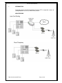
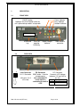
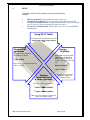
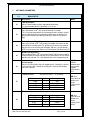
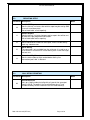
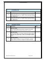
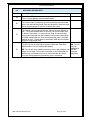
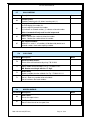
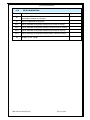
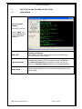
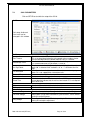
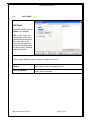
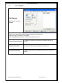
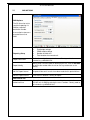
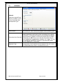
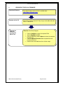
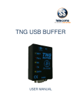
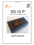
SS-10 C
FIXED CELLULAR TERMINAL – CDMA
USER MANUAL
SS-10C USER MANUAL
Revision History:
Revision 01
Revision 02
Original document
Added Call Back
08 October 2009
10 June 2010
CONTENTS
1
2
2.1
2.2
2.3
3
3.1
3.2
4
5
5.1
5.2
5.3
5.4
5.5
5.6
5.7
5.8
5.9
5.10
6
6.1
7
7.1
7.2
7.3
7.4
7.5
7.6
8
9
10
INTRODUCTION ................................................................................................ 3
FEATURES ........................................................................................................ 4
PHYSICAL FEATURES .............................................................................................. 4
SOFTWARE FEATURES............................................................................................. 4
MAINTENANCE FEATURES ..................................................................................... 4
DESCRIPTION ................................................................................................... 5
FRONT VIEW .............................................................................................................. 5
REAR VIEW ................................................................................................................ 5
SETUP ............................................................................................................... 6
SETTABLE PARAMETERS .............................................................................. 7
BASIC SETUP .............................................................................................................. 7
REPORTING SETUP ................................................................................................... 8
CALL DETAIL REPORTING ...................................................................................... 8
AUTHORIZED USER .................................................................................................. 9
HARDWARE SETTINGS ............................................................................................ 9
NETWORK AND SECURITY ................................................................................... 10
CALL BARRING ....................................................................................................... 11
CALL BACK .............................................................................................................. 11
MISCELLANEOUS .................................................................................................... 11
SETUP INFORMATION ............................................................................................ 12
SERIAL PORT COMMANDS ............................................................................13
SIMPLIFIED SERIAL PORT COMMANDS .............................................................. 13
SETUP OF THE UNIT BY USING THE SS-10 TOOL.......................................14
MAIN WINDOW........................................................................................................ 14
CALL PARAMETERS ............................................................................................... 15
CALL BACK .............................................................................................................. 16
CALL BARRING ....................................................................................................... 17
SMS OPTIONS ........................................................................................................... 18
NETWORK ................................................................................................................ 19
UPGRADE OF THE SS-10C FIRMWARE ........................................................20
TECHNICAL SPECIFICATIONS ......................................................................21
CONTACT DETAILS ........................................................................................22
DOC. NO: SS-10C (REV. 02)
Page 2 of 22
SS-10C USER MANUAL
1
INTRODUCTION
The purpose of the SS-10 C Fixed Cellular Terminal (FCT) is to provide a means of
making telephone calls via the CDMA infrastructure.
ARCHITECTURE
DOC. NO: SS-10C (REV. 02)
Page 3 of 22
SS-10C USER MANUAL
2
FEATURES
2.1
PHYSICAL FEATURES
Matches to complex line impedance
Power saving feed-bridge
Signal level indicator LEDs
Busy indicator
Network indicator
SMA antenna connector
CDMA module On/Off switch allows Network Detach
Power supply 300mA at 12 VDC
RJ11 connector for telephone
DB9 connector for programming
800MHz operation
RUIM/non-RUIM operation
2.2
2.3
SOFTWARE FEATURES
Settable digit count
Settable dial timeout
Transmit & receive levels adjustable
Optional line voltage reversal
Optional line current break
Optional periodic module reboot
4 minute timer to reset CDMA module if not registered on the network
MAINTENANCE FEATURES
Routine periodic SMS reports
Feed bridge voltages
CDMA Module voltage
Failed calls
Total duration of calls
SMS report on zero traffic (no calls made for specified interval)
Request reports
Request setting information
Change set-up information by SMS
2 authorized maintainers
Programmable by serial port, telephone or sms
DOC. NO: SS-10C (REV. 02)
Page 4 of 22
SS-10C USER MANUAL
3
DESCRIPTION
3.1
FRONT VIEW
ON/OFF button
Holding in the On/Off button while the
unit is powered up enables setup mode
Power Indicator
Busy Indicator
Network Indicator
RUIM CARD
RUIM card
tray
3.2
1
4
Press for
opening
RUIM tray
Signal strength
indicator
SMA antenna
connector
REAR VIEW
Line Connector
RJ-11 Connector
(Only pins 2 & 3
are used)
DOC. NO: SS-10C (REV. 02)
PC Connector
DC Connector
DB9 Female - Used for Connects a DC voltage
setup purposes
between 12V and 18V to
Use a standard PC
the unit
serial cable for
Pin
Description
Inside
DC
positive voltage
connecting the unit to
Outside GROUND
a PC
Page 5 of 22
SS-10C USER MANUAL
4
SETUP
Setup of the SS-10C can be done by using one of the following
methods:
SMS Setup Method: Sending SMS commands to the unit;
Telephone Setup Method: Using a telephone connected to the SS-10C;
PC Serial Port Setup Method: Sending commands to the unit by connecting it
to a PC and use a Comms package like HyperTerminal, or
PC Serial Port Setup Method: Connect the unit to a PC using the SS-10C
Tool package
Using SS-10 Toolkit
Load the SS-10 Tool and refer to the notes
“Setup of the unit by using the SS-10
Tool’
Using a
Telephone
Sending SMS
commands
The format of the commands
using SMS is as follows:
Setup Mode must be enabled.
Holding in the On/Off button
while the unit is powered up
enables setup mode on the SS10C.
**<n>*<val>
where <n> is a command number and
<val> is a value.
Dial the following:
<nn>*<ddd>#
Sending
Commands using
a Comms package
Where nn is the parameter
number and ddd is the
required setting.
From the serial port the format is:
**<nn>*<ddd><enter>
or
**<nn>,<ddd><enter>
Where nn is the parameter number and
ddd is the required setting
DOC. NO: SS-10C (REV. 02)
Page 6 of 22
SS-10C USER MANUAL
5
SETTABLE PARAMETERS
5.1
BASIC SETUP
Parameter Description
01
02
Notes
Total Digit Count
Sets the total number of digits required before dialling.
It is recommended that this parameter is set to 10.
Dial Timeout
Sets dial timeout in 10ths of a second. Normally 4 seconds
This is the time taken before the call proceeds when numbers shorter
than the total digit count or international digit count are dialled. The
dial timeout may be overridden by entering ‘#’ after the last dialled
digit.
04
Polarity Reversal Signalling
Sets reversal time in 10ths of a second. To enable reversal on answer,
add 100 to the number input. E.g. 04*20 sets the time to 2.0 seconds
without reversal on answer and setting 04*120 sets it to 2.0 seconds
WITH reversal on answer. Please see “Connection Alert Received (57).”
05
Break Pulse Signalling
Sets the break time in 10ths of a second. Some PABX systems require
a current break to indicate that the call has terminated. The SS-10 can
provide such a break. If it is not required then set this parameter to 0.
06
CLI Restriction
Sets the CLI Restriction status for outgoing calls. Setting this value to
1 will hide the caller’s identity and setting this value to 0 will display
the caller’s identity.
Transmit Levels
07
Relative Level
-12 dB
-6 dB
0 dB
+6 dB
Receive Levels
08
Relative Level
-12 dB
-6 dB
0 dB
+6 dB
DOC. NO: SS-10C (REV. 02)
NB: The
CDMA
network does
not currently
support
International
CLI.
Set transmit levels 1 – 4 (2 normal)
Value
1
2
3
4
Description
Soft
Factory Setting
Louder
Loudest
NB: Unit
must be reset
before new
audio
settings take
effect.
Set receive levels 1 – 4 (2 normal)
Value
1
2
3
4
Description
Soft
Factory Setting
Louder
Loudest
Page 7 of 22
NB: Unit
must be reset
before new
audio
settings take
effect.
SS-10C USER MANUAL
5.2
REPORTING SETUP
Parameter Description
Notes
10
No Call SMS Report
Sets the interval, in minutes, after which a report may be sent by SMS
if no calls have taken place.
Set to 0 to disable ‘no call reporting’.
11
Routine Reports
Sets the interval, in minutes, between routine reports that will be sent
by SMS to the pre-programmed destination.
Set to 0 to disable routine reporting.
12
SMS Report Destination
Sets the destination number for SMS report. Please include country
code. Eg. +27828221381
13
SS-10 Identity
This command is only available from the serial port. It is used to set a
16 character ID so that the SS-10 can identify itself in SMS messages
that are sent.
14
5.3
International Digit Count
Sets the total number of digits needed before dialling if an
international prefix “00” is detected.
CALL DETAIL REPORTING
Parameter Description
20
Notes
Call Record Prefix
Sets up a 2 digit number that will prefix call records that are output
from the SS-10. The prefix is the line of the Extension or Trunk
number to identify the SS-10 to which the CDR record belongs.
DOC. NO: SS-10C (REV. 02)
Page 8 of 22
SS-10C USER MANUAL
5.4
AUTHORIZED USER
Parameter Description
32
33
5.5
Notes
Authorised User 1
Gives authorisation to user 1 for controlling access to the SS-10 unit
via SMS by entering the user’s numbers. Country code to be included,
e.g. +27828221381
Authorised User 2
Gives authorisation to user 2 for controlling access to the SS-10 unit
via SMS by entering the user’s numbers. Country code to be included,
e.g. +27828221381
HARDWARE SETTINGS
Parameter Description
Notes
40
On-Hook Voltage
The On-Hook voltage can be set with this command. The allowed
range is from 20 volts to 40 volts. Nominal value is 35 volts.
41
Off Hook Voltage
The Off-Hook voltage is set using this command. It can be set from 18
to 30 volts. The nominal value is 25 volts. This allows power usage to
be reduced during conversations, which reduces heating in confined
spaces.
42
Peak Ring Voltage
Sets the peak ring voltage. The range is 40 to 60 volts. The factory
setting is 50 volts; normally this setting will not require adjustment.
DOC. NO: SS-10C (REV. 02)
Page 9 of 22
SS-10C USER MANUAL
5.6
NETWORK AND SECURITY
Parameter Description
55
56
57
58
Notes
Power Down Time
Time in minutes between forced network logoffs.
Automatic Call Termination
This feature allows an outgoing call to be automatically disconnected
after a user-defined time period. Enter 0 to disable this feature or enter
the desired time period (in minutes) to enable the feature.
Connection Alert Received
This feature is used in conjunction with “Polarity Reversal Signalling
(04).” The CDMA network does not currently send a connection alert
as default. Connection is assumed on call setup. A true connection
alert can be requested from the network if circumstances demand this
for PABX configuration etc. Enter 0 if no connection alert is received
(default) or enter 1 if arrangements have been made with the network
to receive a connection alert.
RUIM / non-RUIM Mode
The SS-10C can be used with or without a RUIM card. Enter 0 for
RUIM mode or 1 for non-RUIM mode (default).
NB: The unit will refuse network connection if the mode used does not
match the set mode. The unit will not function in non-RUIM mode if a
RUIM card is inserted and vice versa. Please consider this before
using the SMS programming functionality for this command.
DOC. NO: SS-10C (REV. 02)
Page 10 of 22
NB: The unit
must be
rebooted for
the new
setting to
take effect.
SS-10C USER MANUAL
5.7
CALL BARRING
Parameter Description
60
61
62
65
5.8
Notes
Incoming Calls
Prohibits incoming calls (0), allows incoming calls (1).
Display Number Table
Used to display the number list.
An extra digit will precede the number.
(2) Indicates an allowed number, (1) indicates a barred number.
Note: Command will only work in serial setup mode
Add Number
Add a ‘2’ before the number to allow the number.
Add a ‘1’ before the number to bar the number.
Set ‘Require Allowed’
When this is set to ‘1’, all numbers will be barred by default and
allowed numbers have to be explicitly enabled.
CALL BACK
Parameter Description
Notes
70
Erase Call Back Entries.
Erase all the call back entries by using **70*112233
71
Add Entry
Add a number to the call back list. E.g. **71*0821111111
NB. Number must begin with the “0” digit.
72
Delete Entry
Delete a number from the call back list. E.g. **72*0821111111
73
Allow Any Number
Set to 1 allows any number to be called back
Set to 0 enforces the listed numbers
5.9
MISCELLANEOUS
Parameter Description
80
Clear Totals
Resets the report values
81
Set Report Timer
Sets the time interval for the report timer.
DOC. NO: SS-10C (REV. 02)
Notes
Page 11 of 22
SS-10C USER MANUAL
5.10
SETUP INFORMATION
Parameter Description
96
Reboot the CDMA Module
Should be used after level changes.
97
Sends a report back to originator.
Notes
98*1
Sends SMS back to originator displaying first section of settings.
98*2
Sends SMS back to originator displaying second section of settings.
98*3
Sends SMS back to originator displaying third section of settings.
98*4
Sends SMS back to originator displaying fourth section of settings.
99
Displays all the settings.
DOC. NO: SS-10C (REV. 02)
Page 12 of 22
SS-10C USER MANUAL
6
SERIAL PORT COMMANDS
6.1
SIMPLIFIED SERIAL PORT COMMANDS
Simplified basic commands for entering via the serial port generally used for diagnostic or basic
setup purposes.
Instruction
Description
Notes
DR<enter>
Gives a short report on state.
AT<ddddddd><enter>
Sends the data dddd to the cell module.
RESET<enter>
Resets the SS-10.
DIAG<enter>
Toggles the diagnostic state of the SS-10.
REP<enter>
Sends a report SMS to the pre-programmed
destination.
**<nn>*<ddd><enter>
Sets parameter nn to value ddd.
SETID<space><sssss><e
nter>
Sets the ID of the SS-10 to sssss.
This is used to identify the particular SS-10C
(site name?) when automatic SMS messages are
sent.
DOC. NO: SS-10C (REV. 02)
Page 13 of 22
SS-10C USER MANUAL
7
SETUP OF THE UNIT BY USING THE SS-10 TOOL
7.1
MAIN WINDOW
SS-10 Tool Main
Window
Load the SS-10 Tool
Click on COM1, then
click on Refresh to do
automatic baudrate
detection
IMSI +VER
Displays the following:
IMSI, Software Revision and Hardware type of the CDMA engine
SS-10 Firmware revision number.
UpLoad Firmware
To update the firmware, load the Firmware file from the File Menu.
Use UpLoad Firmware button to load the Firmware into the unit.
Refer to the Upgrade Firmware section for the complete procedure.
Show Signal
Tick the Show Signal box for a visual and measured indication of the
signal strength.
DOC. NO: SS-10C (REV. 02)
Page 14 of 22
SS-10C USER MANUAL
7.2
CALL PARAMETERS
Click on SETUP to start with the setup of the SS-10.
Call Parameters:
Call setup, Audio and
Line levels can be
changed in this window.
Call Setup
Dial Timeout
Dialled Digit Count
Int. Digit Count
CLI Restriction
Reversal Time
Reversal on Answer
Break Time
Audio Parameters
TX Level
RX Level
Line Settings
On-Hook Voltage
Off-Hook Voltage
Ring Voltage
DOC. NO: SS-10C (REV. 02)
Sets dial timeout in 10ths of a second
This is the time taken before the call proceeds when numbers shorter
than the total digit count are dialed. Nominal value is 4 seconds
Sets the total number of digits required before dialling.
It is recommended that this parameter is set to 10.
Sets the total number of digits needed before dialling if an international
prefix “00” is detected. Also invoked if a “#” or “*” is dialled as the first
digit.
Hides the number of origin when a call is made to an external party.
Note: CLI is not supported for international calls.
Sets reversal time in 10ths of a second.
Enables or disables Reversal on Answer.
Sets the break time in 10ths of a second. Some PABX systems require a
current break to indicate that the call has terminated. If it is not required
then set this to 0.
Sets Audio Transmit level. Nominal value is 2.
Sets Audio Receive level. Nominal value is 2.
The allowed range is from 20 to 40 volts. Nominal value is 35 volts.
It can be set from 18 to 30 volts. The nominal value is 25 volts. This
allows power usage to be reduced during conversations, which reduces
heating in confined spaces.
The range is 40 to 60 volts. The factory setting is 50 volts, normally this
setting will not require adjustment
Page 15 of 22
SS-10C USER MANUAL
7.3
CALL BACK
Call Back:
Call back numbers can be
added in this window.
NB: In some cases, the
network does not issue a
command to disconnect a
busy call. If this is the
case, the call should be
manually terminated when
the ‘busy’ tone is heard to
allow for call back.
Click on Add or Delete to enter or remove the number from the list.
Number
The call back number to be added to the list
Allow Any Number
When ticked, the call back list will be ignored and any incoming call
number will be called back.
DOC. NO: SS-10C (REV. 02)
Page 16 of 22
SS-10C USER MANUAL
7.4
CALL BARRING
Call Barring:
Calls can be barred or
allowed
Enter the first digits of the number needed to recognise the number type.
Select the Type as BARRED or ALLOWED.
Click on Add or Delete to enter or remove the number from the list.
Require Allowed Numbers
If the block is not ticked it will allow all the numbers that are not
barred.
Allow Incoming Calls
The SS-10 can be set to allow or ignore incoming calls
Auto Call Termination
Automatically terminates an outgoing call after a user-defined “Call
Period”
DOC. NO: SS-10C (REV. 02)
Page 17 of 22
SS-10 USER MANUAL
7.5
SMS OPTIONS
SMS Options:
The SS-10 can be set to
send fault reporting via
SMS to a required
destination number.
It can authorise two users
to control the unit via
SMS.
Feed bridge voltages
CDMA module voltage
Number of failed calls
Total duration of answered calls
Reporting Setup
Report Destination
Destination number for reports to be sent. Country code to be
included, e.g. +27828221381
Report Identity
Identity to be sent with report for identifying the unit. Click on Get IMSI
to retrieve the number from the unit or use any custom text as the
identity.
No Call Report Interval
A report will be sent if no calls have been made for this period of time.
Routine Report Interval
Fixed intervals between sending of reports.
SMS Control Info
Authorised User
Give authorisation to two users for controlling the access to the
SS-10C unit via SMS by entering the user’s numbers. Country code to
be included, e.g. +27828221381
SS-10C USER MANUAL
7.6
NETWORK
Network:
Select the required Reset
Interval if needed, as well
as the Connection Alert
and Operation Type
Reset Interval
Connection Alert Received
Operation Type
DOC. NO: SS-10C (REV. 02)
Set the interval in hours and minutes between forced network log-offs.
This feature is used in conjunction with “Reversal on Answer.” The
Neotel network does not currently send a connection alert as default.
Connection is assumed on call setup. A true connection alert can be
requested from the network if circumstances demand this for PABX
configuration etc. NB. Please ensure that the Connection Alert has
been enabled by the network before setting the “Yes” option. This can
be verified by the “$HFEEPO:” response in the command window
when an outgoing call is connected.
The SS-10C can be used with or without a RUIM card. NB: As a
security feature, the SS-10C will refuse to operate if the unit is set to
non-RUIM mode and a RUIM is inserted and vice versa.
Page 19 of 22
SS-10C USER MANUAL
8
UPGRADE OF THE SS-10C FIRMWARE
Download Firmware
The latest firmware for the SS-10 is available from:
http://www.sstelecoms.com/
Connect unit to PC
Upgrade the
Firmware
by using the
SS-10 Tool
Connect the SS-10 unit to the PC by using a serial cable and make
sure it is switched on.
Load the SS-10 Tool Program:
•
•
•
•
•
DOC. NO: SS-10C (REV. 02)
Click on ComPort to select the required COM.
Set the BaudRate to 9600.
From the File Menu choose Open and select the required
Firmware file.
Click the UpLoad Firmware button to upload the new
firmware to the unit.
Remove the serial cable from the unit after setup.
Page 20 of 22
SS-10C USER MANUAL
9
TECHNICAL SPECIFICATIONS
Housing
LED indicators
Black powder coated Aluminum 147 x 90 x 26 mm
POWER
IN USE
NETWORK
SIGNAL STRENGTH
Connectors
PC connection:
LINE connectors:
POWER connection:
Set-up
Set-up data is stored in non-volatile memory.
Setup can be done by using a telephone or PC.
Compatibility
Required voltage
Current consumption
DOC. NO: SS-10C (REV. 02)
9 way D-Type female
RJ11
2.1 mm DC socket
Compatible with most PABX’s
10 VDC to 16 VDC
300 mA
Page 21 of 22
SS-10C USER MANUAL
10
CONTACT DETAILS
Office:
23 Botha Avenue
Lyttelton Manor
Pretoria, Gauteng
South Africa
Tel:
Fax:
+27 12 664 4644
+27 86 614 5625
E-mail: [email protected]
Postal address:
Postnet Suite 48
Private Bag x 1015
Lyttelton, 0140
Pretoria, Gauteng
South Africa
Sales Support:
South Africa
E-mail: [email protected]
United Kingdom
E-mail: [email protected]
Technical Support:
E-mail: [email protected]
DOC. NO: SS-10C (REV. 02)
Page 22 of 22