1
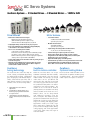
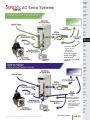
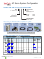
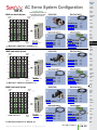
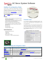
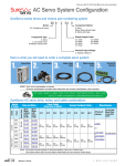
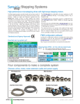
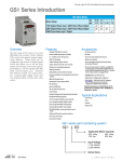
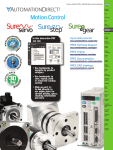
®
AC Servo Systems
Company
Information
Systems
Overview
SureServo™
AC servo systems
The SureServo family of brushless servo
systems from AutomationDirect is fully
digital and offers a rich set of features at
dynamite prices. Choose from eight standard servo motors that are used in combination with one of three standard servo
drives.
• Eight standard systems from 100W to 3kW
• Use with AutomationDirect CLICK,
DirectLOGIC, or P3000 PLCs; or any other
host controller
• Drives feature on-board indexer and
adaptive tuning modes
• Free setup software
• 30-day money-back guarantee
• Two year warranty
Why use a servo?
The SureServo servo systems provide the
highest possible level of performance for
precise control of position, velocity, and
torque. Compared to lower cost stepping
systems, the SureServo products provide:
• More torque at higher speeds
(up to 5,000 rpm)
• Broader range of power (up to 3kW)
• Higher response with closed-loop control
(high hit rate without stalling or
lost position)
Programmable
Controllers
Field I/O
Software
C-more &
other HMI
Drives
SureServo family
The SureServo family is designed for
flexibility and quick implementation.
SureServo drives accept a wide range of
command sources:
• Built-in motion controller w/preset
position, velocity or torque
• Select presets with switch inputs and/or
the multi-drop Modbus serial interface
• Position commands with “pulse and
direction” or “count up and down” format
• Analog voltage Velocity or Torque
command
• Encoder follower
For configuration, tuning and diagnostics, use the drive’s integrated keypad
/display or take advantage of the free
SureServo Pro™ PC-based software.
Tune the system easily with adaptive
auto-tuning selections or a manual
mode.
Adapt to diverse applications with
configurable I/O, including eight digital
inputs, five digital outputs, two analog
monitors and a scalable encoder
output.
Motors &
Gearbox
Steppers/
Servos
Motor
Controls
Proximity
Sensors
Photo
Sensors
Limit
Switches
Encoders
CHECK OUT OUR PRICES
Servo Systems
Soft
Starters
AutomationDirect
Current
Sensors
Allen-Bradley
Digital Servo Drive
$488.00
$1,050.40
Pressure
Sensors
100W Servo Motor
with connectorized Leads
$325.00
SVL-201
$536.31
Temperature
Sensors
Breakout Board Kit for
CN1 Control Interface
$94.00
ASD-BM-50A
$211.09
2090-U3BK-D4401
Pushbuttons/
Lights
10’ Motor
Feedback Cable
$50.00
$83.22
2090-CFBM6DF-CBAA03
Process
10’ Motor
Power Cable
$29.50
SVC-PFL-010
$93.62
Configuration Software
FREE
SV-PRO*
$78.07
2098-UWCPRG
Price/Part Number
Price/Part Number
2098-DSD-005
SVA-2040
TLY-A130T-HK62AA
SVC-EFL-010
Relays/
Timers
2090-CPBM6DF-16AA03
Comm.
Terminal
Blocks &
Wiring
*SureServo Pro software is FREE when downloaded and is also available for $9 on a CD
Complete 1-axis 100W System
$
986.50
2052.71
$
Power
All prices are U.S. list prices, AutomationDirect prices are from April 2012 Price List. The Allen-Bradley
100W system consists of part numbers shown in table above with prices from
www.rockwellautomation.com/en/e-tools 2/20/12.
Circuit
Protection
Enclosures
Tools
Pneumatics
Safety
Appendix
Product
Index
Volume 14
w w w. a u to m at i o n d i re c t . c o m / s e r vo s
Drives/Motors/Motion
e16-23
Part #
Index
®
AC Servo Systems
SureServo Systems ... 3 Standard Drives ... 8 Standard Motors ... 100W to 3kW
Drive features
• Main Power and Control Power Inputs
• Main Power: 230 VAC 1-phase/3-phase
(2kW and 3kW systems are 3-phase only)
• Control Power: 230 VAC Single Phase; 50/60 Hz
• Fully digital with up to 450 Hz velocity loop response
• Easy setup and diagnostics with built-in keypad/display
or the SureServo Pro PC-based software
• Five-in-one command options include:
• ± 10V torque or velocity command
• Pulse train or master encoder position command (accepts
line driver or open collector) with electronic gearing
• Built-in indexer for position control using 8 preset positions
and/or position setpoint with serial Modbus
• Tuning aids include inertia estimation and easy tuning for up to
10 levels of response
• Optically isolated digital inputs (8) and outputs (5), analog
outputs for monitor signals (2), and line driver output for
encoder (with scalable resolution)
SureServo
tuning technology
The SureServo drive closes the loop on
current, velocity, and position (depending
on control mode selection). Proportional
gain, integral gain, feed forward compensation, command low pass filter, and a
notch filter for resonance suppression are
available. There are three tuning modes:
1 . “Manual Mode" for user-defined
adjustments
2. “Easy Mode" for default settings over a
wide range of programmed inertia with
10 response levels
3. “Auto Mode" for automatic adjustment
using an estimated (or measured) value of
inertia
Motor features
• Low inertia models:
• 100W, 200W, 400W, 750W and 1kW
• Speeds up to 5,000 rpm.
• Medium inertia models:
• 1kW, 2kW and 3kW
• Speeds up to 3,000 rpm.
• Square flange mounting with metric dimensions:
• 40, 60, 80, 100, 130 and 180 mm flanges
• Permanent magnet 3-phase synchronous motor
• Keyless drive shafts support clamp-on style coupling
• Integrated encoder with 2,500 (x4) pulses/revolution plus
marker pulse (once per revolution)
• Optional 24 VDC spring-set holding brakes
• Standard hook-up cables for motor power/brake and encoder
• Standard DIN-rail mounted ZIPLink break-out kit for the
drive’s CN1 connector (with screw terminal connections)
SureServo
built-in motion controller
While the SureServo drives can accept
traditional commands from host controls,
they can also provide their own internal
motion control. For example, up to eight
index moves can be pre-defined and
stored in the drive and then selected and
executed using up to three discrete inputs.
The predefined index profiles can also be
changed via serial communications. The
motion can be incremental or absolute
(homing routines are available in the drive)
and acceleration can be linear or S-curve.
SureServo
Optional Holding Brake
Each SureServo model of motor can be
ordered with an optional 24 VDC springset holding brake. This brake holds the
motor in place when power is removed.
Multiple drives can be daisy-chained
and addressed separately using the
drive’s serial port. This allows very simple
yet powerful control of multi-axis processes
that do not need precise path control but
only precise starting and stopping points.
Applications include press feeds, auger
fillers, rotary tables, robots for pick and
place, test or assembly operations, drilling,
cutting, tapping, and similar applications
using simple index moves for single or
multi-axis motion.
Volume 14
e16-24
Drives/Motors/Motion
1 - 80 0 - 633 - 0405
®
AC Servo Systems
Company
Information
Systems
Overview
Programmable
Controllers
Field I/O
Software
C-more &
other HMI
Drives
Soft
Starters
Motors &
Gearbox
Steppers/
Servos
Motor
Controls
• Pulse Train Positions:
• Step and direction
• CW and CCW
• Encoder follower
±10V)
• Analog Velocity (±
±10V)
• Analog Torque (±
• Mode Switching
• “On-the-Fly” Control Mode
Switching
Proximity
Sensors
Photo
Sensors
Limit
Switches
Encoders
Current
Sensors
Pressure
Sensors
Temperature
Sensors
Pushbuttons/
Lights
Process
Relays/
Timers
Comm.
Terminal
Blocks &
Wiring
Power
Circuit
Protection
Enclosures
Stand-alone operation
using internal presets
• Preset selection with
digital inputs
• Ability to change preset
values with serial bus
(RTU/ASCII Modbus
protocols)
Volume 14
w w w. a u to m at i o n d i re c t . c o m / s e r vo s
Drives/Motors/Motion
e16-25
Tools
Pneumatics
Safety
Appendix
Product
Index
Part #
Index
®
AC Servo Systems
How to select and apply
SureServo systems
The primary purpose of the AC servo system is to precisely control
the motion of the load.
The most fundamental
considerations in selecting the servo system are "reflected" load
inertia, servo system maximum speed requirement, servo system
continuous torque requirement, and servo system peak torque
requirement. In a retrofit application, select the largest torque
SureServo system that most closely matches these parameters for
Motion Profile
Desired
Load
Velocity
time
Required
Motor
Torque
Servo
System
Mechanical
Transmission
the system being replaced. In a new application, these
parameters should be determined through calculation and/or
measurement.
AutomationDirect has teamed with Copperhill Technologies to
provide free servo-sizing software. “VisualSizer-SureServo” software will assist in determining the correct motor and drive for your
application by calculating the reflected load inertia and required
speed and torque based on the load configuration. “VisualSizerSureServo”
software
can
be
downloaded
from
www.sureservo.com/downloads.htm.
Information for selecting SureServo systems is also included in
Appendix B of the SureServo User Manual, which can be downloaded from the AutomationDirect.com website.
Load
1. "Reflected" load inertia
The inertia of everything attached to the servo motor driveshaft
needs to be considered and the total "reflected" inertia needs to be
determined. This means that all elements of any mechanical
transmission and load inertia need to be translated into an equivalent inertia as if attached directly to the motor driveshaft. The
ratio of "reflected" load inertia to motor inertia needs to be carefully considered when selecting the servo system.
In general, applications that need high response or bandwidth will
benefit from keeping the ratio of load inertia to motor inertia as
low as possible and ideally under 10:1. Systems with ratios as
high as 200:1 can be implemented, but corresponding lower
bandwidth or responsiveness must be accepted. The servo
response including the attached load inertia is determined by the
servo tuning. SureServo systems may be tuned manually, adaptively with measurement of the load inertia, or set with default
tuning based on a programmed value of load inertia.
2. Torque and speed
With knowledge of the motion profile and any mechanical transmission between the motor and load, calculations can be made to determine the required servo motor continuous torque, peak torque, and
maximum motor speed. The required amount of continuous torque
must fall inside the continuous operating region of the system torquespeed curve (you can check the continuous torque at the average
speed of the motion profile). The required amount of peak torque
must also fall within the servo system's intermittent operating region of
the system torque-speed curve (you need to check this value at the
required maximum speed).
300%
Peak Torque
Limited by Current
Limit
Peak Torque
Limited by Voltage
Limit
Torque
200%
Intermittent Operating
Region
100%
Continuous Operating
Region
1000
2000
3000
4000
5000
Speed (r.p.m.)
Volume 14
e16-26
Drives/Motors/Motion
1 - 80 0 - 633 - 0405
®
AC Servo Systems
Application tip coupling considerations
Company
Information
Systems
Overview
Programmable
Controllers
The SureServo motors have keyless shafts that are designed for
use with clamp-on or compression style couplings. Couplings
using keys and/or set screws should NOT be used with
SureServo motors as they are likely to come loose or damage
the motor shaft. "Servo-grade" clamp-on or compression style
couplings are usually the best choice when you consider the
stiffness, torque rating, and inertia. Higher stiffness (lb-in/radian)
is needed for better response but there is a trade-off between the
stiffness and the added inertia of the coupling. Concerning the
torque rating of the coupling, use a safety factor of 1.25 over the
SureServo peak torque requirement of your application.
Coupling Suppliers: www.sureservo.com/couplingconsiderations.htm
Mechanical transmissions
Common mechanical transmissions include leadscrews, rack &
pinion mechanisms, conveyors, gears, and timing belts. The use
of leadscrew, rack & pinion, or conveyor are common ways to
1. Reduction of reflected
load inertia
As a general rule, it is beneficial to keep
the reflected load inertia as low as possible
while using the full range of servo speed.
SureServo systems can go up to 5,000 rpm
for the low inertia motors and up to 3,000
rpm for the medium inertia motors.
Example: A gearbox reduces the required
torque by a factor of the gear ratio, and
reduces the reflected load inertia by a
factor of the gear ratio squared. A 10:1
gearbox reduces output speed to 1/10,
increases output torque 10 times, and
decreases reflected inertia to 1/100.
However, when investigating the effect of
different speed reduction ratios DO NOT
forget to include the added inertia of
couplings, gearbox, or timing belt pulleys.
These added inertias can be significant,
and can negate any inertia reduction due
to the speed reduction.
translate the rotary motion of the servo motor into linear motion
of the load. The use of a speed reducer such as a gearbox or
timing belt can be very beneficial as follows:
2. Low speed and high torque
applications
If the application requires low speed and
high torque then it is common to introduce a speed reducer so that the servo
system can operate over more of the
available speed range. This could also
have the added benefit of reducing the
servo motor torque requirement which
could allow you to use a smaller and
lower cost servo system. Additional benefits are also possible with reduction in
reflected inertia, increased number of
motor encoder counts at the load, and
increased ability to reject load disturbances due to mechanical advantage of
the speed reducer.
3. Space limitations and motor
orientation
SureServo motors can be mounted in any
orientation, but the shaft seal should not
be immersed in oil (open-frame gearbox,
etc.). Reducers can possibly allow the use
of a smaller motor or allow the motor to
be repositioned. For example, some
reducers would allow for in-line, right
angle, or parallel mounting of the motor.
For more information, refer to the website
listed below.
The following four pages are your ordering guide for the eight
standard SureServo systems. Each of the eight standard systems
has a torque-speed curve including the motor inertia for reference. This is the fundamental information that you need to
select the servo drive and matching motor for your application.
C-more &
other HMI
Drives
Soft
Starters
Motors &
Gearbox
Steppers/
Servos
Motor
Controls
Proximity
Sensors
Photo
Sensors
Limit
Switches
Encoders
Current
Sensors
Pressure
Sensors
Temperature
Sensors
Process
Relays/
Timers
Comm.
Terminal
Blocks &
Wiring
Power
Don't forget the cables and ZIPLink break-out board kit!
Included in the ordering guide are the available connection
cables from the drive to motor in standard lengths from 10 to 60
feet. The break-out board kit includes a 0.5m (19 inch) cable
for the CN1 I/O interface, and is listed for your convenience.
We highly recommend all five items per system as a minimum.
All cables are 100% factory tested to make your system installation as easy and quick as possible. See the Accessories section
for regeneration resistors, AC line filters, fuses, contactors, and
RF noise filters.
Volume 14
w w w. a u to m at i o n d i re c t . c o m / s e r vo s
Software
Pushbuttons/
Lights
www.sureservo.com/mechanical_trans.htm
Ordering guide instructions
Field I/O
Drives/Motors/Motion
e16-27
Circuit
Protection
Enclosures
Tools
Pneumatics
Safety
Appendix
Product
Index
Part #
Index
®
AC Servo System Configuration
SureServo series drives and motors part numbering system
SV A - 2
04
0
Component Option
Series
0: Drive
Blank: Motor without brake
B: Motor with brake
SV: SureServo AC servo
Rated Output Power
Component Type
01: 100W
02: 200W
04: 400W
07: 750W
A: Drive
L: Low inertia motor
M: Medium inertia motor
10: 1000W
20: 2000W
30: 3000W
Nominal Input Voltage
2: 230VAC; 50/60 Hz
Here is what you will need to order a complete servo system:
Servo Drive
Servo Motor
Motor Power
Cable
Motor Encoder
Cable
ZIPLink I/O
Interface
NOTE: UNIT CAN BE PROGRAMMED VIA KEYPAD.
OPTIONAL PROGRAMMING SOFTWARE (FREE DOWNLOAD) AND OPTIONAL PROGRAMMING CABLE AVAILABLE.
SureServo AC servo drive, motor, and cable combinations
Inertia
& Power
SVL-201
SVL-201B
SVL-202
SVL-202B
400W
SVL-204
SVL-204B
750W
SVL-207
SVL-207B
SVL-210
SVL-210B
SVM-210
SVM-210B
SVM-220
SVM-220B
SVM-230
SVM-230B
Power
Servo Drive
Servo
Motor
with
brake
(note)
Inertia
Servo
Motor
without
brake
(note)
Medium inertia
SVA-2040
SVA-2100
1000W
1000W
2000W
3000W
SVA-2300
Low inertia
100W
200W
Power Cables
(from Drive to Motor)
Drive and Motor
Encoder Feedback Cables
10 ft
20 ft
30 ft
60 ft
10 ft
20 ft
30 ft
60 ft
SVCPFL-010
SVCPFL-020
SVCPFL-030
SVCPFL-060
SVCEFL-010
SVCEFL-020
SVCEFL-030
SVCEFL-060
SVCSVCSVCSVCPHM-010 PHM-020 PHM-030 PHM-060
SVCEHH-010
SVCPHH-010
SVCPHH-020
SVCPHH-030
SVCEHH-020
SVCEHH-030
SVCEHH-060
Miscellaneous
ZIPLink I/O
Interface
RS-422/485
Serial Communication
Cable
ZL-RTB50
and
ZL-SVC-CBL50 SVC-MDCOM-CBL
or
ZL-SVC-CBL50-1
or
ZL-SVC-CBL50-2
SVCPHH-060
NOTE: EACH SERVO MOTOR REQUIRES AN ENCODER FEEDBACK CABLE AND A POWER CABLE.
THE MOTOR POWER CABLE INCLUDES BRAKE POWER WIRES FOR THE OPTIONAL MOTOR BRAKE.
Volume 14
e16-28
Drives/Motors/Motion
1 - 80 0 - 633 - 0405
®
AC Servo System Configuration
For all systems:
100W Low Inertia System
Order programming software &
programming cable if needed.
See pgs. 16-31 & 16-32 .
Torque
(N-m)
Field I/O
8.9
7.1
SVL-201
SVL-201B (w/brake)
5.3
<--->
<--->
SVC-PFL-010 (10’)
SVC-PFL-020 (20’)
SVC-PFL-030 (30’)
SVC-PFL-060 (60’)
<--->
<--->
<--->
<--->
Speed
(rpm)
SVA-2040 <--->
Jm= Motor Inertia = 0.000027 lb-in-s2 (0.000003 kg - m2)
SVC-EFL-010 (10’)
SVC-EFL-020 (20’)
SVC-EFL-030 (30’)
SVC-EFL-060 (60’)
<--->
<--->
<--->
<--->
ZL-RTB50 <--->
and one cable below:
ZL-SVC-CBL50 (0.5m) <--->
ZL-SVC-CBL50-1 (1m) <--->
ZL-SVC-CBL50-2 (2m) <--->
200W Low Inertia System
Torque
(N·m)
17.7
1.5
1.0
SVL-202
SVL-202B (w/brake)
13.3
Intermittent
Duty Zone
<--->
<--->
SVC-PFL-010 (10’)
SVC-PFL-020 (20’)
SVC-PFL-030 (30’)
SVC-PFL-060 (60’)
<--->
<--->
<--->
<--->
0
0
1000
2000
3000 4000 5000
200W Low Inertia
Speed
(rpm)
SVA-2040 <--->
Jm= Motor Inertia = 0.00016 lb-in-s2 (0.000018 kg - m2)
SVC-EFL-010 (10’)
SVC-EFL-020 (20’)
SVC-EFL-030 (30’)
SVC-EFL-060 (60’)
<--->
<--->
<--->
<--->
ZL-RTB50 <--->
and one cable below:
ZL-SVC-CBL50 (0.5m) <--->
ZL-SVC-CBL50-1 (1m) <--->
ZL-SVC-CBL50-2 (2m) <--->
400W Low Inertia System
Torque
(N·m)
35.4
SVL-204
SVL-204B (w/brake)
26.6
<--->
<--->
SVC-PFL-010 (10’)
SVC-PFL-020 (20’)
SVC-PFL-030 (30’)
SVC-PFL-060 (60’)
<--->
<--->
<--->
<--->
Pushbuttons/
Lights
Process
Relays/
Timers
Circuit
Protection
Enclosures
Pneumatics
8.9
Speed
(rpm)
Power
Tools
17.7
0
400W Low Inertia
Current
Sensors
Terminal
Blocks &
Wiring
44.3
Continuous
Duty Zone
Encoders
Comm.
Torque
(in-lb)
Intermittent
Duty Zone
Limit
Switches
Temperature
Sensors
4.4
Continuous Duty Zone
0
Motor
Controls
Pressure
Sensors
8.9
0.5
Steppers/
Servos
Photo
Sensors
22.1
2.0
Motors &
Gearbox
Proximity
Sensors
Torque
(in·lb)
2.5
C-more &
other HMI
Soft
Starters
1.8
0
100W Low Inertia
Software
Drives
3.5
Continuous
Duty Zone
Systems
Overview
Programmable
Controllers
Torque
(in-lb)
Intermittent
Duty Zone
Company
Information
SVA-2040 <--->
SVC-EFL-010 (10’)
SVC-EFL-020 (20’)
SVC-EFL-030 (30’)
SVC-EFL-060 (60’)
<--->
<--->
<--->
<--->
ZL-RTB50 <--->
and one cable below:
ZL-SVC-CBL50 (0.5m) <--->
ZL-SVC-CBL50-1 (1m) <--->
ZL-SVC-CBL50-2 (2m) <--->
Jm= Motor Inertia =0.0003 lb-in-s2 (0 .000034 kg - m2)
Volume 14
w w w. a u to m at i o n d i re c t . c o m / s e r vo s
Drives/Motors/Motion
e16-29
Safety
Appendix
Product
Index
Part #
Index
®
AC Servo System Configuration
For all systems:
750W Low Inertia System
Torque
(N-m)
Order programming software &
programming cable if needed.
See pgs. 16-31 & 16-32.
Torque
(in-lb)
88.5
70.8
53.1
Intermittent
Duty Zone
SVL-207
SVL-207B (w/brake)
<--->
<--->
SVC-EFL-010 (10’)
SVC-EFL-020 (20’)
SVC-EFL-030 (30’)
SVC-EFL-060 (60’)
<--->
<--->
<--->
<--->
SVC-PFL-010 (10’)
SVC-PFL-020 (20’)
SVC-PFL-030 (30’)
SVC-PFL-060 (60’)
<--->
<--->
<--->
<--->
35.4
17.7
Continuous
Duty Zone
0
750W Low Inertia
Speed
(rpm)
SVA-2100 <--->
Jm= Motor Inertia = .00096 lb-in-s2 (0.000108 kg - m2)
ZL-RTB50 <--->
and one cable below:
ZL-SVC-CBL50 (0.5m) <--->
ZL-SVC-CBL50-1 (1m) <--->
ZL-SVC-CBL50-2 (2m) <--->
1 kW Low Inertia System
Torque
(N·m)
Torque
(in·lb)
10.0
88.5
8.0
70.8
Intermittent
Duty Zone
6.0
53.1
SVL-210
SVL-210B (w/brake)
<--->
<--->
SVC-PHM-010 (10’)
SVC-PHM-020 (20’)
SVC-PHM-030 (30’)
SVC-PHM-060 (60’)
<--->
<--->
<--->
<--->
SVC-EHH-010 (10’)
SVC-EHH-020 (20’)
SVC-EHH-030 (30’)
SVC-EHH-060 (60’)
<--->
<--->
<--->
<--->
ZL-RTB50 <--->
and one cable below:
ZL-SVC-CBL50 (0.5m) <--->
ZL-SVC-CBL50-1 (1m) <--->
ZL-SVC-CBL50-2 (2m) <--->
35.4
4.0
Continuous
Duty Zone
2.0
17.7
0
0
1000
0
2000
3000
5000
4000
1 kW Low Inertia
Speed
(rpm)
SVA-2100 <--->
Jm= Motor Inertia = .0023 lb-in-s2 (0.00026 kg - m2)
1 kW Medium Inertia System
................................................................................
................................................................................
................................................................................
................................................................................
................................................................................
Torque
Torque
(N-m)
(in-lb)
......................................................................
25 ...................................................................... 221.3
......................................................................
20 ...................................................................... 177.0
......................................................................
15 ...................................................................... 132.8
SVM-210
<--->
SVM-210B (w/brake) <--->
SVC-PHM-010 (10’)
SVC-PHM-020 (20’)
SVC-PHM-030 (30’)
SVC-PHM-060 (60’)
<--->
<--->
<--->
<--->
SVC-EHH-010 (10’)
SVC-EHH-020 (20’)
SVC-EHH-030 (30’)
SVC-EHH-060 (60’)
ZL-RTB50 <--->
and one cable below:
ZL-SVC-CBL50 (0.5m) <--->
ZL-SVC-CBL50-1 (1m) <--->
ZL-SVC-CBL50-2 (2m) <--->
......................................................................
Intermittent
10 ...................................................................... 88.5
......................................................................
Duty Zone
5 ...................................................................... 44.3
Continuous
......................................................................
Duty Zone
0
0
1000
2000
1 kW Medium Inertia
3000
4000
5000
Speed
(rpm)
0
SVA-2100 <--->
Jm= Motor Inertia = .0053 lb-in-s2 (0.000598 kg - m2)
<--->
<--->
<--->
<--->
Volume 14
e16-30
Drives/Motors/Motion
1 - 80 0 - 633 - 0405
®
AC Servo System Configuration
For all systems:
2 kW Medium Inertia System
Order programming software &
programming cable if needed.
See pgs. 16-31 & 16-32.
................................................................................
................................................................................
................................................................................
................................................................................
................................................................................
Field I/O
25 ...................................................................... 221.3
......................................................................
20 ...................................................................... 177.0
......................................................................
SVC-PHH-010 (10’)
SVC-PHH-020 (20’)
SVC-PHH-030 (30’)
SVC-PHH-060 (60’)
SVM-220
<--->
SVM-220B (w/brake) <--->
132.8
15 ......................................................................
Duty Zone
<--->
<--->
<--->
<--->
......................................................................
10 ...................................................................... 88.5
......................................................................
0
1000
2000
3000
4000
2 kW Medium Inertia
5000
0
SVC-EHH-010 (10’)
SVC-EHH-020 (20’)
SVC-EHH-030 (30’)
SVC-EHH-060 (60’)
SVA-2300 <--->
Speed
(rpm)
Jm= Motor Inertia = .014 lb-in-s2 = (0.00158 kg - m2)
ZL-RTB50 <--->
and one cable below:
ZL-SVC-CBL50 (0.5m) <--->
ZL-SVC-CBL50-1 (1m) <--->
ZL-SVC-CBL50-2 (2m) <--->
<--->
<--->
<--->
<--->
3 kW Medium Inertia System
................................................................................
................................................................................
................................................................................
................................................................................
C-more &
other HMI
Drives
Motors &
Gearbox
Steppers/
Servos
Motor
Controls
Proximity
Sensors
Photo
Sensors
Torque
Torque
(N-m)
(in-lb)
......................................................................
................................................................................
Software
Soft
Starters
Continuous
44.3
5 ......................................................................
Duty Zone
......................................................................
0
Systems
Overview
Programmable
Controllers
Torque
Torque
(N-m)
(in-lb)
......................................................................
Intermittent
Company
Information
50 ...................................................................... 442.5
......................................................................
40 ...................................................................... 354.0
......................................................................
SVC-PHH-010 (10’)
SVC-PHH-020 (20’)
SVC-PHH-030 (30’)
SVC-PHH-060 (60’)
SVM-230
<--->
SVM-230B (w/brake) <--->
30 ...................................................................... 265.5
<--->
<--->
<--->
<--->
Intermittent
......................................................................
Limit
Switches
Encoders
Current
Sensors
Duty Zone
20 ...................................................................... 177.0
......................................................................
Pressure
Sensors
88.5
10 ......................................................................
Continuous
......................................................................
Temperature
Sensors
Duty Zone
0
0
1000
2000
3000
4000
3 kW Medium Inertia
5000
Speed
(rpm)
0
SVC-EHH-010 (10’)
SVC-EHH-020 (20’)
SVC-EHH-030 (30’)
SVC-EHH-060 (60’)
SVA-2300 <--->
Jm= Motor Inertia = 0.038 lb-in-s2 = (0.00433 kg - m2)
ZL-RTB50 <--->
and one cable below:
ZL-SVC-CBL50 (0.5m) <--->
ZL-SVC-CBL50-1 (1m) <--->
ZL-SVC-CBL50-2 (2m) <--->
<--->
<--->
<--->
<--->
NOTE: ALL MOTOR POWER CABLES INCLUDE BRAKE
POWER WIRES FOR THE OPTIONAL MOTOR BRAKE.
SureServo Communications Cables for Muti-drop Networks
Product
Price
Pushbuttons/
Lights
Process
Relays/
Timers
Comm.
Terminal
Blocks &
Wiring
Power
Circuit
Protection
Description
Enclosures
<--->
RS-422/485 serial communication cable for use with multidrop networks; 3ft length; IEEE 1394
plug to unterminated wires; compatible with all SureServo systems.
Facilitates connection between the SureServo drive serial port and host controllers.
<--->
ZIPLink SureServo Drives cable with 6-pin RJ12 connector to a 6-pin IEEE 1394 connector, shielded, twisted pair, 2.0 meter (6.6 ft.) length. For RS-232 connection to all SureServo amplifiers.
SVC-485RJ12-CBL-2 *
<--->
ZIPLink SureServo amplifier communication cable, RJ12 male to 6-pin IEEE 1394 connector,
shielded, twisted pair, 2.0 meter (6.6 ft.) length. Cable used in conjunction with ZL-CDM-RJ12xxx
distribution module can access a compatible RS-485 device network.
Safety
SVC-485HD15-CBL-2 *
<--->
ZIPLink SureServo Drives cable with a HD 15-pin male to a 6-pin IEEE 1394 connector, shielded,
twisted pair, 2.0 meter (6.6 ft.) length. For RS-485 connection to all SureServo amplifiers.
Product
Index
SVC-MDCOM-CBL
SVC-232RJ12-CBL-2 *
Tools
Pneumatics
Appendix
* Refer to the ZIPLinks Wiring Solutions section for complete information regarding the ZIPLink cables.
Volume 14
w w w. a u to m at i o n d i re c t . c o m / s e r vo s
Drives/Motors/Motion
e16-31
Part #
Index
®
AC Servo System Software
SureServo Pro configuration software
SureServo Pro is an optional free downloadable configuration
software package for the SureServo drives. With SureServo Pro
installed, the personal computer may be directly connected to the
servo drive's serial port via the PC's RS-232 serial port*. A sixfoot configuration cable (SVC-PCCFG-CBL, <--->) is available
to make the connection between the drive serial port and PC
DB-9 serial port simple.
*Note: Use our USB-RS232 converter cable in conjunction with the SVC-PCCFGCBL cable on PCs having only USB ports.
Features
• Quick Start - The basic setup when you have limited time and just
want to get up and running ASAP.
• Maintenance keypad allows the user to operate the servo system
from the PC. This is a great aid during start-up to allow the servo to
perform some basic motion and to check the I/O.
• Detailed - The complete setup for all the drive parameters
• Tune and check the servo response live using the scope feature.
• Upload and download the drive setup. Save the drive setup as a
file for future use.
• Edit the drive setup
• View all drive faults
• Trend drive variables in real time
System Requirements
Parameter views
The SureServo Pro configuration tool logically organizes over
165 servo drive parameters into five tabbed groups. Each
parameter has a factory default that usually allows the servo to
run “out-of-the-box”.
The parameters can be easily changed with available options or
setting ranges displayed. Tuning modes and parameters can
also be changed using SureServo Pro. After the parameters have
been defined, the complete setup can be stored and archived.
Drive configurations can be uploaded, edited, saved, and downloaded as often as necessary.
Parameter View Example Screen - Basic Parameters
• Windows 7, Windows 2000, XP Pro
• 24 MB of RAM
• 16 MB hard disk
• RS232 serial port or USB port
• Internet Explorer 4.0 or higher (for HTML help support)
SureServo Software and Configuration Cables
Product
Price
Description
SV-PRO
Free
SureServo Pro configuration software for use with all SureServo servo systems.
FREE download from www.sureservo.com or www.automationdirect.com websites.
SV-PRO
<--->
CD with SureServo Pro configuration software
SVC-PCCFG-CBL
<--->
SVC-485CFG-CBL-2 * <--->
Six-foot RS-232 communications cable; connects servo drive serial port to PC DB-9 serial port.
For PCs having only USB ports, use our USB-RS232 converter cable in conjunction with the SVC-PCCFG-CBL cable.
ZIPLink SureServo amplifier configuration cable, 6-pin IEEE 1394 connector to RJ45 connector, shielded, twisted pair, 2.0 meter (6.6 ft.) length.
Use this cable in conjunction with our USB-485M serial adapter to connect any SureServo amplifier to a PC. Eliminates the need to reprogram networked servo drives from RS485 to RS232 when connecting to a PC.
* Refer to the ZIPLinks Wiring Solutions section for complete information regarding ZIPLink cable SVC-485CFG-CBL-2.
Volume 14
e16-32
Drives/Motors/Motion
1 - 80 0 - 633 - 0405
Motor Controller Communication
Drive / Motor Controller (GS/DuraPulse/SureServo/SureStep/Stellar) ZIPLink Selector
Drive / Motor Controller
Controller
Comm Port Type Network/Protocol Connects to
DL06 PLCs
RJ12
RS-485 Modbus RTU
Cable
Comm Port Type Cable
(2 meter length) Connectors
Port 2 (HD15)
GS-485HD15-CBL-2
GS-EDRV100
RJ12
GS-EDRV-CBL-2
ZL-CDM-RJ12Xxx*
RJ12
GS-485RJ12-CBL-2
FA-ISOCON
5-pin Connector
GS-ISOCON-CBL-2
D2-260 CPU
GS1
ZIPLink Cable
Communications
CLICK PLCs
DL05 PLCs
RJ12 to HD15
RJ12 to RJ12
RJ12 to 5-pin plug
Other Hardware
Required
–
–
–
–
–
–
Port 2 (RJ12)
–
DL06 PLCs
RS-232 Modbus RTU
D2-250-1 CPU
Port 2 (HD15)
GS-RJ12-CBL-2
RJ12 to RJ12
FA-15HD
D2-260 CPU
GS2
RJ12
D4-450 CPU
Port 3 (25-pin)
FA-CABKIT
P3-550 CPU
Port 2 (RJ12)
–
DL06 PLCs
Port 2 (HD15)
GS-485HD15-CBL-2
RJ12
GS-EDRV-CBL-2
ZL-CDM-RJ12Xxx*
RJ12
GS-485RJ12-CBL-2
FA-ISOCON
5-pin Connector
GS-ISOCON-CBL-2
RJ12 to 5-pin plug
Port 2 (HD15)
GS-485HD15-CBL-2
RJ12 to HD15
GS-EDRV100
RJ12
GS-EDRV-CBL-2
ZL-CDM-RJ12Xxx*
RJ12
GS-485RJ12-CBL-2
5-pin Connector
GS-ISOCON-CBL-2
D2-260 CPU
RS-485 Modbus RTU
GS-EDRV100
DL06 PLCs
D2-260 CPU
DuraPulse
(GS3)
RJ12
RS-485 Modbus RTU
FA-ISOCON
CLICK PLCs
DL05 PLCs
RJ12 to HD15
RJ12 to RJ12
RJ12 to RJ12
RJ12 to 5-pin plug
–
–
–
–
–
–
–
–
–
–
–
Port 2 (RJ12)
–
DL06 PLCs
RS-232 Modbus RTU
D2-250-1 CPU
Port 2 (HD15)
SVC-232RJ12-CBL-2
6-pin IEEE to RJ12
FA-15HD
D2-260 CPU
SureServo
IEEE1394 (CN3)
D4-450 CPU
Port 3 (25-pin)
FA-CABKIT
P3-550 CPU
Port 2 (RJ12)
–
DL06 PLCs
RS-485 Modbus RTU
–
Port 2 (HD15)
SVC-485HD15-CBL-2
6-pin IEEE to HD15
ZL-CDM-RJ12Xxx*
RJ12
SVC-485RJ12-CBL-2
6-pin IEEE to RJ12
–
USB-485M
RJ45
SVC-485CFG-CBL-2
6-pin IEEE to RJ45
–
Port 2 (HD15)
SR44-485HD15-CBL-2 RJ45 to HD15
RJ12
SR44-485RJ45-CBL-2 RJ45 to RJ12
Port 2 (HD15)
STP-232HD15-CBL-2
D2-260 CPU
–
DL06 PLCs
Stellar
(Soft Starter)
SR44 Series
RJ45**
RS-485 Modbus RTU
D2-250-1 CPU
D2-260 CPU
ZL-CDM-RJ12Xxx*
–
DL06 PLCs
D2-250-1 CPU
SureStep
RJ12
RS-232 ASCII
HD15-pin to RJ12
CLICK PLCs
–
–
D2-260 CPU (Port2)
DL05 PLCs
SR44-RS485**
RJ12
STP-232RJ12-CBL-2
RJ12 to RJ12
–
–
* When using the ZL-CDM-RJ12Xxx ZIPLink Communication Distribution Module, replace the lowercase xx with the number of RJ12 ports, i.e.4 for four ports or10 for
ten ports. (ex: ZL-CDM-RJ12X4 or ZL-CDM-RJ12X10)
** The SR44-RS485 Communications Adapter must be installed for RS-485 communications with the Stellar soft starters.
Volume 14
e29-90
Terminal Blocks/Wiring Solutions
1 - 80 0 - 633 - 0405
Precision Servo Gearboxes
Features
SureGear™ Servo
Gearbox Overview
The SureGear PGA series of high-precision servo gear reducers
is an excellent choice for applications that require good accuracy
and reliability at an exceptional value. This in-line planetary
gear reducer has a thread-in mounting style, along with a level
of precision and torque capacity that is best in its class. Offered
in a concentric shaft design with a maximum five arc-min backlash rating, the SureGear PGA series is an accurate, highperformance, and cost effective solution for any OEM.
The machining quality of the SureGear PGA helical planetary
gears provides a very quiet and more efficient reducer than other
competitive products that are similarly priced. The SureGear
PGA series easily mates to SureServo motors, and is the perfect
solution for applications such as gantries, injection-molding
machines, pick-and-place automation, and linear slides.
SureGear™ Servo Gearbox Selection
• Industry-standard mounting dimensions
• Thread-in mounting style
• Best-in-class backlash (5 arc-min)
• Four gear ratios available (5, 10, 15, 25:1)
• Mounting hardware included for attaching to SureServo motors
• Helical-cut planetary gears for quiet operation and reduced vibration
• Uncaged needle roller bearings for high rigidity and torque
• Adapter bushing connection for simple and effective attachment to
most servo motors
• High-viscosity, anti-separation grease does not migrate away from the
gears; no leakage through the seal
• Maintenance free: No need to replace the grease for the life of the unit
• At nominal speed, service life is 20,000 hours
• Can be positioned in any orientation
• 5-year warranty
Applications
• Linear slides
• Packaging machines
• Conveyors
• Gantries
• Injection-molding machines
• Pick-and-place automation
SureGear Servo Gearbox Selection
SureServo Gear
Motor
Ratio
SVL-201(B)
SVL-202(B)
SVL-204(B)
SVL-207(B)
SVL-210(B)
SVM-210(B)
SVM-220(B)
SVM-230(B)
SureGear
Gearbox
Motor Nominal Combination Nominal Combination
Combination
Output Torque
Output Torque
Nominal Output Max Output
( N·m [lb·in] )
( N·m [lb·in] )
Speed ( rpm ) Speed ( rpm )
Available Load Inertia
@ 5:1 Mismatch *
( kg·cm2 [lb·in·s2] )
5
PGA070-05A1
1.59 [14.1]
600
1,000
10
PGA070-10A1
3.18 [28.1]
300
500
9.40 [0.008]
15
PGA070-15A1
4.77 [42.2]
200
333
21.38 [0.019]
25
PGA070-25A1
7.95 [70.4]
120
200
60.63 [0.054]
5
PGA070-05A2
3.20 [28.3]
600
1,000
18.50 [0.016]
10
PGA070-10A2
6.40 [56.6]
300
500
76.00 [0.067]
15
PGA070-15A2
9.60 [85.0]
200
333
171.00 [0.151]
25
PGA070-25A2
16.00 [141.6]
120
200
481.25 [0.426]
5
PGA070-05A2
6.35 [56.2]
600
1,000
38.50 [0.034]
10
PGA070-10A2
12.70 [112.4]
300
500
156.00 [0.138]
15
PGA070-15A2
19.05 [168.6]
200
333
351.00 [0.310]
25
PGA070-25A2
31.75 [281.0]
120
200
981.25 [0.868]
5
PGA070-05A3
11.95 [105.8]
600
900
126.00 [0.111]
10
PGA090-10A3
23.90 [211.5]
300
450
465.00 [0.411]
15
PGA090-15A3
35.85 [317.3]
200
300
1053.00 [0.931]
25
PGA090-25A3
59.75 [528.8]
120
180
2931.25 [2.593]
5
PGA090-05A4
16.50 [146.0]
600
900
252.50 [0.223]
10
PGA090-10A4
33.00 [292.1]
300
450
1020.00 [0.902]
15
PGA120-15A4
49.50 [438.1]
200
300
2295.00 [2.030]
25
PGA120-25A4
82.50 [730.2]
120
180
6375.00 [5.639]
5
PGA090-05A5
24.00 [212.4]
400
600
675.00 [0.597]
10
PGA090-10A5
48.00 [424.8]
200
300
2710.00 [2.397]
15
PGA120-15A5
72.00 [637.3]
133
200
6097.50 [5.393]
25
PGA120-25A5
120.00 [1062.1]
80
120
16937.50 [14.981]
5
PGA120-05A6
47.00 [416.0]
400
600
1700.00 [1.504]
94.00 [832.0]
200
300
6800.00 [6.015]
10
0.32 [2.8]
0.64 [5.7]
1.27 [11.2]
2.39 [21.2]
3.30 [29.2]
4.80 [42.5]
PGA120-10A6
PGA-155-10A6
9.40 [83.2]
1.83 [0.002]
15
PGA155-15A6
141.00 [1239.1]
133
200
15300.00 [13.533]
25
PGA155-25A6
235.00 [2079.9]
80
120
42500.00 [37.591]
5
PGA120-05A6
71.50 [632.8]
400
600
5137.50 [4.544]
143.00 [1265.7]
200
300
20550.00 [18.176]
10
PGA120-10A6
PGA155-10A6
14.30 [126.6]
15
PGA155-15A6
214.50 [1898.5]
133
200
46237.50 [40.897]
25
PGA155-25A6
357.50 [3164.1]
80
120
128437.50 [113.603]
* Available load inertia is calculated based on servo motor inertia using the formula: Available Inertia = (5·Motor Inertia – Gearbox Inertia)·(Gear Ratio)2
A 5:1 inertia mismatch is a good target for design purposes. Systems with lower or higher mismatch may be possible, depending on operating conditions.
Volume 14
e16-50
Drives/Motors/Motion
1 - 80 0 - 633 - 0405
Precision Servo Gearboxes
Company
Information
Pricing & Specifications
Systems
Overview
Programmable
Controllers
640
[144]
530
[119]
0.056
PGA070-15A1
<--->
15:1
double
18
[159]
35
[310]
80
[708]
740
[166]
630
[142]
0.055
PGA070-25A1
<--->
25:1
double
27
[239]
50
[443]
100
[885]
870
[196]
790
[178]
0.053
PGA070-05A2
<--->
5:1
single
27
[239]
50
[443]
100
[885]
510
[115]
390
[88]
0.160
single
18
[159]
35
[310]
80
[708]
640
[144]
530
[119]
0.140
35
[310]
80
[708]
740
[166]
630
[142]
0.140
0.130
PGA070-10A2
<--->
10:1
70
Allowable Radial Load
( N [lb] )
Allowable Thrust Load
( N [lb] )
SVL-201(B)
PGA070-15A2
<--->
15:1
double
PGA070-25A2
<--->
25:1
double
27
[239]
50
[443]
100
[885]
870
[196]
790
[178]
50
[443]
100
[885]
510
[115]
390
[88]
0.360
PGA070-05A3
<--->
5:1
single
PGA090-10A3
<--->
10:1
single
50
[443]
80
[708]
200
[1770]
1200
[270]
1600
[360]
0.750
PGA090-15A3
<--->
15:1
double
50
[443]
80
[708]
200
[1770]
1400
[315]
1900
[427]
0.720
PGA090-25A3
<--->
25:1
double
75
[664]
125
[1106]
250
[2213]
1600
[360]
2200
[495]
0.710
PGA090-05A4
<--->
5:1
single
75
[664]
125
[1106]
250
[2213]
960
[216]
1200
[270]
2.900
50
[443]
80
[708]
200
[1770]
1200
[270]
1600
[360]
2.800
single
75
[664]
125
[1106]
250
[2213]
960
[216]
1200
[270]
2.900
80
[708]
200
[1770]
1200
[270]
1600
[360]
2.800
PGA090-10A4
PGA090-05A5
<--->
<--->
10:1
5:1
single
5
10:1
single
PGA120-15A4
<--->
15:1
double
120
[1062]
225
[1991]
500
[4425]
2300
[517]
3000
[674]
2.800
PGA120-25A4
<--->
25:1
double
180
[1593]
330
[2921]
625
[5532]
2700
[607]
3700
[832]
2.800
PGA120-15A5
<--->
15:1
double
120
[1062]
225
[1991]
500
[4425]
2300
[517]
3000
[674]
2.800
330
[2921]
625
[5532]
2700
[607]
3700
[832]
2.800
PGA120-25A5
<--->
25:1
double
PGA120-05A6
<--->
5:1
single
180
[1593]
330
[2921]
625
[5532]
1600
[360]
1900
[427]
11.000
single
120
[1062]
225
[1991]
500
[4425]
2000
[450]
2500
[562]
11.000
240
[2124]
470
[4160]
1000
[8851]
4700
[1057]
4100
[922]
240
[2124]
470
[4160]
1000
[8851]
5400
[1214]
4900
11.000
[1102]
360
[3186]
700
1250
[6196] [11063]
6400
[1439]
6100
11.000
[1371]
PGA155-10A6
<--->
10:1
single
PGA155-15A6
<--->
15:1
double
PGA155-25A6
<--->
25:1
double
155
2000 4000
Soft
Starters
Motors &
Gearbox
Motor
Controls
Limit
Switches
Encoders
Pressure
Sensors
3.5
[7.7]
SVL-207(B)
4.0
[8.8]
Temperature
Sensors
Pushbuttons/
Lights
IP55
SVL-210(B)
3.5
[7.7]
SVM-210(B)
8.7
[19.2]
SVL-210(B)
8.7
[19.2]
SVM-210(B)
Process
Relays/
Timers
Comm.
Terminal
Blocks &
Wiring
Power
Circuit
Protection
Enclosures
Tools
95
16
[35.3]
11.000
90
Pneumatics
7.8
[17.2]
Safety
SVM-220(B)
SVM-230(B)
18
[40.0]
Volume 14
w w w. a u to m at i o n d i re c t . c o m / s e r vo s
Drives
Current
Sensors
1.5
[3.3]
90
180
[1593]
10:1
1.7
[3.7]
3.5
[7.7]
C-more &
other HMI
Photo
Sensors
SVL-202(B)
SVL-204(B)
90 °C
[194 °F]
Software
Proximity
Sensors
95
<--->
<--->
1.5
[3.3]
90
PGA090-10A5
PGA120-10A6
95
95
50
[443]
120
1.7
[3.7]
90
27
[239]
90
90
Field I/O
Steppers/
Servos
1.5
[3.3]
95
18
[159]
3000 6000
Fits SureServo Servo Motor
80
[708]
Environmental Rating
35
[310]
0.077
Approx Weight ( kg [lb] )
18
[159]
390
[88]
Maximum Housing Temperature
single
510
[115]
Efficiency (%)
10:1
Moment of Inertia (kg·cm2)
<--->
Maximum Input Speed (rpm)
PGA070-10A1
Nominal Input Speed (rpm)
Emergency Stop Torque
( N·m [lb·in] )
single
Backlash (arc-min)
Maximum Acceleration Torque
( N·m [lb·in] )
5:1
100
[885]
Frame Size (mm)
<--->
50
[443]
Price
Reduction
PGA070-05A1
27
[239]
Part Number
Ratio
Nominal Output Torque
( N·m [lb·in] )
SureGear™ Precision Servo Gearboxes
Drives/Motors/Motion
e16-51
Appendix
Product
Index
Part #
Index