1
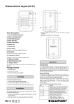
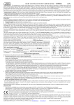
Wireless PIR Motion Sensor (IR-S1)
Parts Description
Installation
1. Learn/Test Button & LED indicator
Press the button to transmit a learn/test code and enter Test
mode for 3 minutes. The LED will light up whenever a movement
is detected under Test mode.
The PIR Sensor has knockouts on the back where plastic is
thinner. The 2 center knockouts are for flat wall mounting, and the
4 side knockouts are for corner mounting.
2. Battery Insulator
1. Break through the knockouts; use the knockouts to mark
position on the wall or corner.
3. Supervision Enable/Disable Jumper Switch
(JP2)
4. High/Low Sensitivity Jumper Switch (JP3)
5. Tamper Switch
The Tamper switch protects the PIR from unauthorized cover
opening.
2. Drill holes into the wall or corner using the knockouts as
template.
3. Fix the PIR Sensor base onto the wall with the screws and
plugs provided.
4. Replace the PIR Sensor cover onto the base.
Package Content
Corner Fixing
Knockouts x 4
1 x PIR Sensor
4 x wall plugs and screws
Surface Fixing
Knockouts x 2
(Inside)
2 x 1.5V alkaline batteries (pre-installed)
Supervision Enable/Disable Jumper Switch (JP2)
Jumper On
Jumper Off
The jumper link is inserted
connecting the two pins
if the jumper link is removed
or parked on one pin.
If enabled, the PIR sensor will transmit supervision signal to
Control Panel periodically for the sensor to monitor PIR sensor
condition.
Jumper set to ON = supervision function is Disabled (Default)
Jumper set to OFF = supervision function is Enabled
High/Low Sensitivity Jumper Switch (JP3)
Jumper On
Jumper Off
The jumper link is inserted
connecting the two pins
if the jumper link is removed
or parked on one pin.
Jumper set to ON = PIR sensitivity is set to High
Jumper set to OFF= PIR sensitivity is set to Low (Default)
Learning
Put the Control Panel into learning mode, then press the learn
button to transmit learn code. Please refer to Control Panel
manual for to complete the learning process.
Operation
Sleep Timer
The PIR features a “sleep time” of approximately 1 minute for
power conservation. After transmitting a detected movement, the
PIR will not retransmit for 1 minute. Any further movement
detected during this sleep period will extend the sleep time by
another minute. In this way continuous movement in front of a
PIR will not unduly exhaust the battery.
Test Mode
Press the Test Button to enter Test mode for 3 minutes. Sleep
timer will be disabled under Test mode, and the LED indicator will
flash every time a movement is detected. Use the Test mode to
determine PIR detection coverage and plan the installation
location accordingly.
LED Indicator
Off
On (2 seconds)
Normal Operation
- When Tamper Switch is triggered
- Movement detection under low battery,
tamper triggered, or Test mode.
Battery
The PIR uses two alkaline 1.5 V batteries as its power source. It
also features low battery detection function to notify the Control
Panel when the battery voltage is low.
When PIR is on low battery, follow the procedure below to
change the batteries.
1. Open the PIR back cover.
2. Remove the old batteries.
3. Press the tamper switch several times to fully discharge.
4. Insert the new batteries observing correct polarity. The PIR
LED will light up for 30 seconds to indicate it is warming up.
5. Replace the PIR back cover.
Specification
Environmental Condition
-10°C to 40°C, relative humidity 85% non-condensing.
Radio
433 MHz
FCC Statement
This device complies with Part 15 of the FCC Rules. Operation is
subject to the following two conditions:
(1) This device may not cause harmful interference, and
(2) This device must accept any interference received, including
interference that may cause undesired operation.
FCC Caution:
To assure continued compliance, any changes or modifications
not expressly approved by the party responsible for compliance
may void the user's authority to operate this equipment. (Example
- use only shielded interface cables when connecting to computer
or peripheral devices).