1
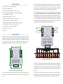
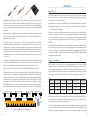
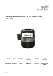
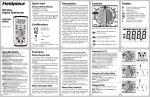
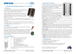
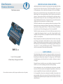
Zero Emission
Vehicles Australia
Protecting your Lithium Batteries
http://www.zeva.com.au
Lithium batteries have been a revolution in energy storage and a major enabling factor in the
resurgence of electric vehicles. However they can be easily damaged if their voltage goes out
of safe operating range – either too high (from overcharging) or too low (over-discharging).
Battery packs are commonly built from a large number of individual cells in series to achieve
higher voltages. Due to manufacturing tolerances, cells will always have some variation in
capacity, so during use there will be some cells which get full or go flat before others. In
battery packs made of many cells in series, the overall voltage gives little indication of the
voltage of individual cells in the chain, so it is important to have a system which monitors the
voltages of each cell, and takes action if any cell goes out of range.
ZEVA’s BMS12 modules offer a robust, automotive-grade solution for protecting your lithium
batteries from damage, maintaining pack balance, and monitoring cell voltages remotely. A
single module can manage anywhere between 3–12 lithium cells, and up to 16 modules may
be used on the same CAN bus allowing packs up to 192 cells or about 600VDC.
The BMS12 modules communicate over CAN bus with a BMS master control unit to form
a complete Battery Management System for your vehicle. Voltage thresholds are fully
configurable, allowing the module to be compatible with most lithium chemistries including
LiFePO4, LiCo, LiPo and LiMn.
BMS12
Battery Management Systems should be considered the last line of defence for your battery
pack. During normal operation, the BMS should never have to intervene with vehicle
operation, only taking action to protect the battery in exceptional circumstances. Although a
BMS will protect your cells from damage from over-discharging, regularly discharging your
cells to 0% SoC – i.e driving until the BMS stops the vehicle – will drastically shorten the
cycle life of your batteries so is best avoided whenever possible.
v1.2
12-cell, CAN bus-enabled
Lithium Battery Management Module
Safety Warning
Electric Vehicle battery packs contain a lot of energy and can deliver a lot of power, with
potentially lethal voltages and currents. Proper precautions and electrical safety procedures
should always be observed when working on EVs. Voltages above 110VDC should be
considered dangerous, and vehicles should never be worked on while power contactor(s)
are engaged.
Please read this manual carefully to ensure correct installation and operation of your BMS12
modules. If you are unsure of anything, please contact us before proceeding.
Please read these instructions carefully for proper installation and use of this product.
We have endeavoured to make a safe and reliable product which performs as described,
however since ZEVA has no control over the integration of its products into a vehicle, we can
assume no responsibility for the safety or functionality of the completed vehicle.
It is the responsibility of the end user to determine the suitability of the products for the
purpose employed, and the end user assumes all risks associated. Products should only be
installed by suitably qualified and experienced persons, and should always be used in a safe
and lawful manner.
1
If cells are distributed in multiple groups around the vehicle, we do not recommend setting
the BMS up as a fully centralised system (that is, with HV flyleads from every cell coming to a
group of modules at a single location in the vehicle) because the long HV flyleads are subject
to greater EMI noise and greater change of potentially dangerous wiring faults.
Specifications
• Cells managed: 3–12 lithium cells per module
• Maximum total voltage: 60VDC
• Compatible chemistries: LiFePO4, LiCo (LiPo), LiMn, etc
• High, low and shunt voltage thresholds: Configurable, 0–5000mV
• Accuracy: Within 0.25% (<10mV)
• Operating temperature range: -40˚C to 85˚C
• Pack balancing: Timed 30Ω shunts (~120mA, up to 1hr)
• Temperature sensing: Dual 100KΩ NTC thermistors
• Cell quiescent current draw: 1.6mA (idle) 2.2mA (when sampling)
Once mounted, connect flywires between the 13-pin plug and the cells as per the diagram
below, starting with the most negative (near the – sign) and working up to the most positive
(near the + sign). It is best to leave the plug disconnected from the module while wiring up,
and verify all voltages / cell orders before connecting to the module. If fewer than 12 cells
are to be connected, some cell inputs at the positive end will be unused. These should be
electrically bridged to the highest cell connection such that they are all at the same potential
and will read as zero volts. Add this bridge before attaching any cells.
• CAN power supply: 12V nominal (7-16V range), 20mA
• CAN bus specification: 125kbps, 2.0A standard
Shield
Ground
CAN L
CAN H
12VDC
• Dimensions: 80 x 76 x 10mm
• Weight: 35g
CAN BUS
CAN BUS
12VDC
CAN H
CAN L
Ground
Shield
Installation
TEMP1
The module has four 3.2mm (1/8”) mounting holes at the corners as per the diagram below
which can be used to securely mount the module. If fastening above metal surfaces, use
standoffs or an insulating layer in between to ensure that the circuit board does not contact
the metal, which could cause short circuits. Modules should be installed in a location
protected from water and debris – typically, inside sealed battery enclosures is ideal.
+
70mm
TEMP2
ZEVA BMS1 v1.4 (c) 2014
–
Most positive cell
CAN BUS
TEMP1
TEMP2
ZEVA BMS1 v1.4 (c) 2014
62mm
70mm
CAN BUS
Most negative cell
Figure 2: Typical wiring for BMS12 module
Figure 1: BMS12 module dimensions and mounting pattern
The Molex C-Grid SL plugs are designed for fairly small gauge wire, around 24-30AWG. The
wire’s insulation needs to be small enough to fit into the plug housing, which limits outer
diameter to about 2mm. The best way to connect wires to pins is crimping first then adding a
little solder to the joint. A suitable crimping tool is available from vendors such as Altronics
(part T1537).
It is best to mount the module close to the cells it is monitoring, with flylead lengths of 50cm
or less recommended to minimise induced EMI noise and the chance of wiring/insulation
faults.
If you don’t have a suitable crimping tool, you can the solder wire directly to the plug,
ensuring minimal gap between the insulation and the back of the pin. You may need to
compress the wings on the pin insert a little for them to fit comfortably into the housing.
–
+
78mm
2
3
Operation
Powering up
(1)
(2)
The BMS12 modules run most of their circuitry from CAN bus power. When the module
powers up, if there are no errors you should see a bright blue light on the board. This light
may also indicate error codes as follows:
(3)
When the pin is fully inserted, a barb on the pin should engage a slot in the housing to lock
it in place, and a faint click should be heard. Either inspect visually or give a gentle tug on
the wire after insertion to ensure it is secure. Pins can be removed if necessary by applying
pressure on the pin’s barb with a jeweler’s screwdriver, then the pin can be pulled from the
housing.
• Blinking once per second: No cells detected, or communication failure with cell sampler
• Flashing twice per second: No CAN requests for over 1 second – possible CAN bus fault
or no master control unit present.
There are no visual signs of whether monitored cells are within range or if shunts are active.
This must be monitored over CAN bus by an appropriate BMS master control unit, which
is also able to take action in the event of a cell voltage or temperature error. Please refer
to the user manual for your BMS master control unit for advice on integration with BMS12
modules.
Be very careful to avoid short circuits or reverse polarities when attaching flyleads for the
module, as lithium batteries can discharge dangerous current levels and wiring faults can
damage the BMS12 module.
Plugs for the CAN bus use 5-pin Molex C-Grid SL which are wired similarly to the cell
connector. Shielded twisted pair cable is recommended for CAN bus wiring, with two
conductor pairs – one pair for CAN signals, and one pair for bus power. (During operation, the
traction circuit in electric vehicles can emit fairly high levels of electromagnetic interference,
which can induce noise on signal wiring.) This type of wire is a little uncommon, but you
can either purchase it from us or we can recommend vendors who may carry it in your part
of the world.
Your complete BMS should be “failsafe”, so if any BMS12 modules are not detected by the
MCU on startup, or if any cells are out of safe voltage range, the vehicle should not be able
to drive or be charged. It is a good idea to verify the failsafe by unplugging one of the flyleads
to the cells or unplug the CAN bus, and verify that this causes the MCU to stop the charger
or shut down the drive system.
Note that the cell sampling electronics is galvanically isolated from the CAN bus electronics
in order to maintain isolation between your traction circuit and vehicle chassis. There should
also be no external electrical connections between HV wiring and CAN bus wiring.
Voltage Thresholds
BMS12 modules will come from the factory pre-programmed with voltage thresholds
according to customer request/requirements (LiFePO4 by default), but the thresholds can
also be reprogrammed anytime over CAN bus with an appropriate BMS master controller, or
a ZEVA EVMS Monitor. The following table lists recommended voltage thresholds for Lithium
Iron Phosphate (LiFePO4), Lithium Cobalt (LiCo) and Lithium Manganese (LiMn) cells.
Ensure all wiring is secured so it will not become damaged from vibration or abrasion.
BMS12
BMS12
–
+
B+
+
–
–
+
+
–
–
+
+
–
BMS12
–
+
–
+
+
–
–
+
+
–
–
+
+
–
–
+
+
–
–
+
+
–
–
+
+
–
MCU
–
+
–
+
+
–
–
+
+
–
–
+
+
–
–
+
+
–
–
+
+
–
–
+
+
–
Figure 3: Example wiring for a 32-cell battery pack
4
Chemistry
–
+
–
+
–
+
B-
Nom Voltage
Min Voltage
Max Voltage Charge / Shunt
Temp Range
LiFePO4
3.2V
2.5V
3.8V
3.65V
-20˚C – 60˚C
LiCo
3.7V
3.0V
4.2V
4.0V
-20˚C – 60˚C
LiMn
3.7V
3.0V
4.2V
4.0V
-20˚C – 40˚C
120!
120!
For optimum performance, CAN buses should be wired as a single daisy chain of devices
(without branching), and need to be terminated at both ends of the bus with a 120Ω resistor
across the CAN H and CAN L lines. A suitable resistor has been included with the module,
but should only be used with the final module in the chain. Modules and the MCU may be
in any order on the CAN bus, and the MCU does not have to be an endpoint (it could be
in the middle of the bus). Usually the CAN bus route requiring the shortest cable lengths is
best. The diagram below shows an typical topology for an example 32-cell battery pack.
To charger,
contactors
etc
We recommend setting your charge voltage (per cell) and shunt voltage threshold to the
same value. This way only high cells will shunt at the end of a charge cycle, and if the pack
is perfectly balanced, no shunt balancing will occur.
LiCo cells have the highest energy density but also the highest volatility and are often run
very close to their safety limits. Cell manufacturers typically recommend charging to 4.2V,
while cells can suffer damage above 4.3V. As such we recommend a slightly lower charge
5
voltage until you are confident that your pack is balanced to very close tolerances before
charging to 4.2V/cell. (Due to the non-linear charge curve of lithium batteries, there is very
little charge between 4.0V and 4.2V so minimal capacity is sacrificed.)
Lithium Polymer (LiPo) actually refers to a type of construction rather than a chemistry, but
the vast majority of cells marketed as LiPo are Lithium Cobalt (LiCo) chemistry.
automatic Pack balancing
In battery packs built from many cells, optimum performance is attained when all cells are at
the same State of Charge – also known as pack balance.
The BMS12 modules use a system known as “shunt balancing” to maintain balance, which
switches on small resistors across any cells which go above a programmed shunt threshold.
In this way cells with higher than average voltage will have some of their energy dissipated
in order to bring their state of charge back down towards the average.
The BMS12 uses a novel approach of small shunt resistors left on for a long time using timers,
which keeps component size small and heat generated low, while still being able to balance
a significant amount of energy each charge.
Shunt balancers are not able to balance a pack completely in a single charge so we recommend
manually balancing your cells prior to initial pack assembly (by charging each cell individually).
However the shunts will get an unbalanced pack incrementally closer to balanced each charge,
and once balanced are able to maintain perfect balance with minimal shunting.
CAN Protocol Details
For those wishing to integrate BMS12 modules with their own master control unit, we have
prepared an application note detailing the required CAN format and packet IDs/structures.
Please download a copy from the BMS12 product page at http://www.zeva.com.au.
Tech support and warranty information
BMS12 modules are covered by a 12 month warranty against manufacturing faults or failures
under normal operating conditions. The warranty does not cover misuse of the product,
including but not limited to physical damage or modification to the module, and reverse or
excessive voltages to inputs.
We have taken great care to design a safe and reliable product, but faults can happen. If
you believe your BMS12 module has a fault, please contact us via our website for RMA
information. Or if you have any questions not covered by this manual, please contact us via
our website:
http://www.zeva.com.au/Contact
ZEVA is a carbon neutral business.
All products proudly designed and manufactured in Australia.
6
7