1
Application Note: Embedded Processing
R
XAPP997 (v1.1) June 14, 2010
Summary
Reference Design: LogiCORE™ OPB USB
2.0 Device
Author: Geraldine Andrews, Vidhumouli Hunsigida
The application note demonstrates the use of the On-Chip Peripheral Bus (OPB) Universal
Serial Bus (USB) 2.0 Device in a MicroBlaze™ based reference system.
This application note describes the:
•
Configuration of the EDK reference system.
•
USB Mass Storage standalone software application
•
Endpoint Read Write application that includes the Device firmware, the Windows Device
Driver and the Windows application
The OPB USB 2.0 Device reference system is targeted for the Xilinx Virtex®-4 ML401
Evaluation Platform.
Included
Systems
The reference system for the Xilinx Virtex-4 ML401 Evaluation Platform is included with this
application note. The reference system is available at:
https://secure.xilinx.com/webreg/clickthrough.do?cid=55646
Introduction
The OPB USB 2.0 Device core performs the functionality of a USB high speed device and is
compliant with the USB 2.0 Specification. It has a 32-bit OPB slave interface and a ULPI
(UTMI(1) + Low Pin Interface) interface to an external USB PHY. Detailed information about the
ULPI interface can be found at www.ulpi.org. The USB 2.0 Device core does not support any
DMA operations.
A daughter card from SMSC with the ULPI PHY, EVB-USB3300-XLX, is connected to the
ML401 Evaluation platform. The daughter card may be powered either through the USB cable
connecting to the PC or through the ML401 Board. More information on the daughter card
specifications can be obtained from SMSC.
The software applications provided with this reference system are executed from the external
DDR memory.
Note that the USB 2.0 Device core is a licensed core and in the absence of a license, the core
ceases to function on hardware after some time. For this reference system, operating at an
OPB clock frequency of 66.67 MHz, the core times out after 13 hours and 45 minutes.
1. USB 2.0 Transceiver Macrocell Interface
© 2007-2010 Xilinx, Inc. All rights reserved. All Xilinx trademarks, registered trademarks, patents, and further disclaimers are as listed at http://www.xilinx.com/legal.htm.
PowerPC is a trademark of IBM Inc. All other trademarks and registered trademarks are the property of their respective owners. All specifications are subject to change without
notice.
XAPP997 (v1.1) June 14, 2010
www.xilinx.com
1
R
Hardware and Software Requirements
Hardware and
Software
Requirements
Daughter Card
Set Up
The hardware and software requirements are:
•
Xilinx Virtex-4 ML401 Evaluation Platform
•
SMSC Daughter card with a ULPI PHY interface
•
Xilinx Platform USB cable or Parallel IV programming cable
•
RS232 serial cable and serial communication utility (HyperTerminal)
•
USB cable to connect the PC port and the daughter card port
•
Xilinx Platform Studio 9.1.02i
•
Xilinx Integrated Software Environment (ISE®) 9.1.02i
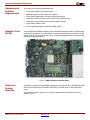
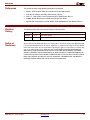
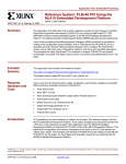
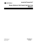
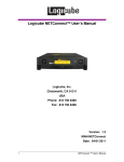
The connection of the SMSC daughter card on the ML401 Evaluation Platform is done through
the expansion header J6. Pins 2 through 26 of this expansion header are used to connect the
signals of the ULPI PHY to the FPGA. Figure 1 shows the SMSC daughter card connected to
the ML401 Evaluation Platform.
X997_01_042707
Figure 1: SMSC Daughter Card connection
Reference
System
Specifics
XAPP997 (v1.1) June 14, 2010
The reference system has the MicroBlaze processor along with the MCH OPB DDR, the OPB
UART Lite, the OPB Interrupt Controller (OPB INTC), the OPB Timer, and the OPB GPIO
cores.
The reference system is shown Figure 2 and the address map of the reference system is
shown in Table 1.
www.xilinx.com
2
R
Reference System Specifics
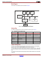
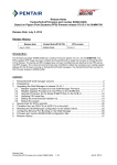
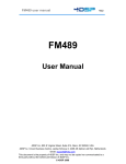
Block Diagram
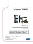
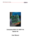
The IP cores in the reference system are shown in Figure 2.
Xilinx Virtex™-4 FPGA
OPB
GPIO
MicroBlaze
Processor
OPB
INTC
OPB
UARTLITE
OPB Bus
OPB
USB 2.0 DEVICE
OPB
TIMER
ULPI Interface
MCH OPB
DDR
X997_02_042707
ULPI PHY
Figure 2: Reference System Block Diagram
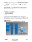
Address Map
The address mapping for the IP cores in the reference system is given in Table 1.
Table 1: Reference System Address Map
Peripheral
Instance
Base Address
High Address
lmb_bram_if_cntlr
dlmb_cntlr, ilmb_cntlr
0x00000000
0x00001fff
mch_opb_ddr
DDR_SDRAM_64Mx32
0x24000000
0x27ffffff
opb_uartlite
RS232_Uart
0x40600000
0x4060ffff
opb_gpio
opb_gpio_0
0x40800000
0x408FFFFF
opb_mdm
debug_module
0x41400000
0x4140ffff
opb_timer
opb_timer_0
0x41c00000
0x41c0ffff
opb_intc
opb_intc_0
0x46000000
0x46ffffff
opb_usb2_device
opb_usb2_device_0
0x47000000
0x47FFFFFF
System Configuration
This Xilinx Virtex-4 ML401 Evaluation platform based reference system has the MicroBlaze
processor with the MCH OPB DDR SDRAM used as the external memory.
The vbus_detect, running, high_speed, suspend, disconnect, configured, spare1, and spare2
pins of the OPB USB 2.0 Core are connected to the LED’s on the board through the OPB GPIO
core.
The OPB INTC core handles the interrupt signals from the USB 2.0 Device core and the OPB
Timer core.
XAPP997 (v1.1) June 14, 2010
www.xilinx.com
3
R
Reference System Specifics
Interrupt Control Logic
The USB 2.0 Device core generates an interrupt depending on several conditions. This
interrupt signal is directly routed to the processor through the OPB INTC core in the system.
The application software running on the MicroBlaze processor will manage the interrupt
handling.
Software Applications
This section describes the two software applications provided along with the reference system.
The user is expected to change the Vendor ID before use of the USB 2.0 Device core in their
applications.
The two software applications provided with this reference system are
•
Mass storage application: The software application is found under the project root
directory massstorage/src/xusb_storage.c
•
Endpoint read write application: The software application is found under the project root
directory endpointrdwr/src/xusb_endpointrdwr.c
The software application is executed from the external DDR memory and should be marked to
not load into BRAM. The linker script has all options set to the external memory.
Each application has code that runs on the ML401 evaluation platform and code that runs on
the Windows PC.
The code that runs on the ML401 evaluation platform has the basic device driver code, the USB
specification chapter 9 related code and the application specific code.
The device driver code provides the routines needed for accessing and configuring the USB 2.0
Device core registers. The following are the device driver files:
•
xusb.c: This file contains the functions needed to execute basic operations like
initialization, start, stop, and reset, for a USB device.
•
xusb.h: This file is the main driver header file. It contains the driver data structures and the
driver function prototype declarations.
•
xusb_l.h: This header file contains all the register offsets, register bit masks and two basic
macros for reading and writing the core registers.
•
xusb_sinit.c: This file contains the static initialization function definition.
•
xusb_config.c: This file contains the driver function definitions needed for configuring the
USB 2.0 device.
•
xusb_intr.c: This file contains the USB 2.0 device interrupt related function definitions.
•
xusb_endpoint.c: This file contains the endpoint related function definitions.
The chapter 9 code implements the operations needed by the USB 2.0 device during the
enumeration process with the USB host into which the device is connected. In addition to the
enumeration functions, the chapter 9 code contains the functions needed during the device
normal operation for communicating over control endpoint (endpoint 0). The following are the
chapter 9 files:
•
xusb_cp9.c: This file contains the USB 2.0 specification chapter 9 related functions.
•
xusb_cp9.h: This file contains the chapter 9 related function prototype definitions.
•
xusb_types.h: This file contains constant definitions and structure definitions related to
USB protocol.
The application specific code handles all the USB protocol and “Plug and Play” related events
such as USB Suspend, USB Resume, and USB Reset over the endpoints by using the
callbacks provided by the driver interrupt handler.
XAPP997 (v1.1) June 14, 2010
www.xilinx.com
4
R
Reference System Specifics
The mass storage device requires the standard windows device driver on any Windows PC for
a mass storage device.
The endpoint read write application requires a special windows device driver and a demo
software to be run on the host PC.
The following sections describe the specific details about the Mass Storage Application and the
Endpoint Read Write Application.
Mass Storage Application
This software application provides the use of the USB 2.0 device as a mass storage device.
The software application implements the class specific protocol handling and the bulk transfer
related command processing needed for a mass storage device. It implements the basic
features of the mass storage device like store, read, and write operations and the hot “Plug and
Play” feature of a USB device and it does not implement the full functionality of a USB mass
storage class device.
The software application configures two user endpoints and one control endpoint on the USB
device. Endpoint 0 is configured as the control endpoint. Endpoint 1 is configured as BULK
OUT and endpoint 2 is configured as BULK IN. Both the endpoints are configured for a
maximum packet size of 512 bytes. The remaining five endpoints are not used. The ML401
evaluation platform running the mass storage application appears as an un-formatted mass
storage device of 8MB size to the host PC to which it is connected on the USB interface. The
mass storage application allows the user to format, copy, read, modify, and save the files on the
ML401 evaluation platform RAM area.
Endpoint Read Write Application
This application demonstrates the usage of the USB 2.0 device for doing IN/OUT transfers for
all the endpoints.
There are three different components of this application:
•
Device Firmware
•
Windows Device Driver
•
Windows Application
Device Firmware
The device firmware configures the USB 2.0 device on the ML401 evaluation platform for
communicating with the USB host for simple I/O operations. It configures three endpoints of the
USB 2.0 device as BULK IN with maximum packet size as 512 bytes, three endpoints as BULK
OUT with maximum packet size of 512 bytes and one endpoint as INTERRUPT IN with
maximum packet size as 16 bytes. The device firmware receives data from the host over the
endpoints with BULK OUT configuration, sends data to host over the endpoints with BULK IN
configuration and uses the endpoint with INTERRUPT IN configuration for sending device
status to the host.
This device firmware is built around the Xilinx Micro Kernel and is initiated during the init phase
of the kernel. This application has only one file xusb_endpointrdwr.c and is located under the
project root directory at endpointrdwr/src/.
Windows Device Driver
This is the USB Windows device driver for Windows XP. It provides the driver interface needed
for the USB application to execute the simple I/O operations with the USB 2.0 device on the
ML401 evaluation platform. The windows device driver supports a USB device with the same
configuration as described in the device firmware section. The windows device driver files
along with the Windows INF installation file can be found under the project root directory at
xilinxdd/driver. The driver binary file xilinx.sys is located under the project root directory
xilinx/driver/objfre_wxp_x86/i386.
XAPP997 (v1.1) June 14, 2010
www.xilinx.com
5
R
Executing the Reference System
Windows Application
This is the windows application executed on the Windows XP PC connected to the ML401
evaluation platform over the USB 2.0 Device interface. The windows application opens six
channels with the six endpoints of the USB 2.0 Device on the ML401 evaluation platform. The
application then sends 32768 bytes of data over BULK OUT endpoints of the USB 2.0 Device
and receives the same data over the BULK IN endpoints of the USB device. The channel
opened for write is closed when the USB device on the ML401 evaluation platform receives the
complete data. Similarly, the channel opened for read will be closed once the host receives
32768 bytes of data from the USB device.
The application ends after all the read-write channels are closed. The windows application files
can be found under the project root directory at xilinxdd/usbapp:
•
usbapp.cpp: This file contains the main function which starts the read write threads.
•
usb.cpp: This file contains the init, open, read, write, and ioctl routines used in the main
function.
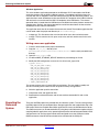
Writing a new user application
1. Create a drivers folder under project root directory.
2. Copy the usb_v1_00_a directory from
$XILINX_EDK/sw/XilinxProcessorIPLib/drivers into the newly created drivers
directory.
3. Open the xusb_types.h file.
4. Un-define MASS_STORAGE_DEVICE definition by commenting out Line 6
5. Modify the USB configuration structure at Line 310 of xusb_types.h file.
typedef struct {
USB_STD_CFG_DESC stdCfg;
USB_STD_IF_DESC ifCfg;
USB_STD_EP_DESCepCfg1;
USB_STD_EP_DESCepCfg2;
USB_STD_EP_DESCepCfg3;
USB_STD_EP_DESCepCfg4;
USB_STD_EP_DESCepCfg5;
USB_STD_EP_DESCepCfg6;
USB_STD_EP_DESCepCfg7;
} FPGA1_CONFIGURATION;
The current structure uses all seven USB user end points. The user needs to modify this
structure according to the number of user end points used by the application.
6. Write the application specific source files.
7. Compile the driver and application files.
8. Download the hardware bitstream and the new software executable file and run the
application.
Executing the
Reference
System
XAPP997 (v1.1) June 14, 2010
There are two EDK project files provided with this reference system. The massstorage.xmp is
the EDK project file for the standalone Mass Storage application and endpointrdwr.xmp is the
EDK project file for the Endpoint Read Write application that uses the Windows device driver.
The reference system can be executed either by using the pre-built bitstream together with the
compiled software applications, or by generating the bitstream and software executable in EDK.
A HyperTerminal or similar program needs to be configured to use the COM port and the
RS232 connector of the ML401 board needs to be connected to the COM port.
www.xilinx.com
6
R
Executing the Reference System
Executing the Reference System using the Pre-Built Bitstream and the
Compiled Software Applications
To execute the system using files inside the ready_for_download directory in the project
root directory, follow these steps:
1. Change directories to the ready_for_download directory. Within this directory, change
the directory to either massstorage or endpointrdwr depending on the application
chosen.
2. Use iMPACT to download the bitstream by using the following command:
impact -batch xapp997.cmd
3. Invoke XMD and connect to the MicroBlaze processor by using the following command:
xmd -opt xapp997.opt
4. Download the executable by using the following command:
dow executable.elf
Executing the Reference System from EDK
To execute the system using EDK, follow these steps:
1. Create an environment variable XIL_PLACE_ALLOW_LOCAL_BUFG_ROUTING and set its
value to ‘1’.
2. Open the desired XMP file (massstorage.xmp or endpointrdwr.xmp) inside EDK.
3. Use Hardware→Clean Hardware to clean previously generated hardware files.
4. Use Hardware→Generate Bitstream to generate a bitstream for the system.
5. Use Software→Clean Software to clean the previously generated software
libraries/applications.
6. Use Software→Build All User Applications to build the software application.
7. Download the bitstream to the board with Device Configuration→Download Bitstream.
8. Launch XMD with Debug→Launch XMD
9. Download the executable files by using the following command:
dow executable.elf
XAPP997 (v1.1) June 14, 2010
www.xilinx.com
7
R
Executing the Reference System
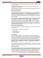
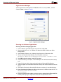
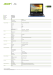
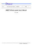
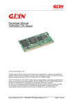
HyperTerminal Settings
Set the HyperTerminal to Baud Rate of 115200, Data Bits to 8, Parity to None, and Flow
Control to None as shown in Figure 3.
X997_03_042707
Figure 3: HyperTerminal Settings
Running the Software Applications
Running the Mass Storage Application
1. Run the software application using the run command inside XMD.
2. After the application is run, the Windows PC detects the USB 2.0 Device as a Mass
Storage device.
3. Open Windows Explore to see the device being displayed as a Removable Disk.
4. Click on the Removable Disk directory. The PC prompts a message
The disk in drive is not formatted. Do you want to format it now?
5. Click YES to format the device for the FAT file system.
6. Once the formatting is complete, a new window opens with the Removable Disk directory
path.
7. Copy a file from any of the drives and paste it under the Removable Disk directory.
8. Open the copied file from the Removable Disk directory and make modifications and save
the file.
9. Now, copy the file from the Removable Disk directory and paste it in any other directory.
10. Close the window of the Removable Disk and disconnect the USB cable from the PC. The
hyperterminal should display the message:
USB Disconnect
11. Reconnect the USB cable and observe that the device is detected and the Removable Disk
directory shows up again. Verify that the content of the copied file still exists.
XAPP997 (v1.1) June 14, 2010
www.xilinx.com
8
R
Conclusion
Running the Endpoint Read Write Application
1. Run the software application using the run command inside XMD.
2. Upon running the software, the PC detects the USB 2.0 Device as a new hardware and a
wizard pops up for installation of the device driver for this new USB device.
3. Select the option to install the driver from a list or specific location.
4. Specify the path of the driver under the project directory as xilinxdd/driver and follow
the instructions as given by the wizard.
5. At this point, a warning appears in the Hardware Installation process, mentioning that the
software has not passed the Windows logo testing. Bypass this warning by clicking on the
Continue Anyway tab.
6. The wizard next asks for the xilinxdd.sys file for completing the installation.
7. Select the file from the path xilinxdd/driver/objfre_wxp_x86/i386
8. The PC completes the installation and gives the message
Your new hardware is installed and is ready to use
9. After the installation of the driver, run the usbapp.exe file under the directory
xilinxdd/usbapp/objfre_wxp_x86/i386.
10. We see messages on the command shell displaying that the USB channels for endpoints 16 have opened successfully and the three write threads for endpoints 1, 2, and 3 and the
three read threads for endpoints 4, 5, and 6 have started.
11. At this point, the PC would be sending and receiving data to and from the USB 2.0 Device.
WriteThread 1 start
WriteThread 2 start
...
12. After a while, we see that the messages reading
ReadThread 6 end
WriteThread 3 end
indicating that the test on those endpoints is over.
13. The hyperterminal displays the bytes written and read.
14. The command shell disappears once all endpoints are tested.
Conclusion
XAPP997 (v1.1) June 14, 2010
This application note describes how to set up the OPB USB 2.0 Device in a MicroBlaze
processor system. The reference system is built for the Xilinx Virtex-4 ML401 Evaluation
Platform. The system can be used to test the USB 2.0 Device core in a Mass Storage
application and in an endpoint read-write application.
www.xilinx.com
9
R
References
References
Revision
History
Notice of
Disclaimer
XAPP997 (v1.1) June 14, 2010
The current versions of the following documents are referred:
•
DS591, OPB Universal Serial Bus 2.0 Device Product Specification
•
usb_20.pdf, Universal Serial Bus Specification, Rev 2.0
•
ULPI_v1_1.pdf, UTMI++ Low Pin Interface (ULPI) Specification, Rev 1.1
•
UG082, ML40x EDK Processor Reference Design User Guide
•
Specification for daughter card from SMSC, EVB-USB3300-XLX User Manual, Rev 0.1
The following table shows the revision history for this document.
Date
Version
Revision
5/15/07
1.0
Initial Xilinx release.
6/14/10
1.1
Incorporated CR557659 to correct link on pg 1 to ref system.
Xilinx is disclosing this Application Note to you “AS-IS” with no warranty of any kind. This Application Note
is one possible implementation of this feature, application, or standard, and is subject to change without
further notice from Xilinx. You are responsible for obtaining any rights you may require in connection with
your use or implementation of this Application Note. XILINX MAKES NO REPRESENTATIONS OR
WARRANTIES, WHETHER EXPRESS OR IMPLIED, STATUTORY OR OTHERWISE, INCLUDING,
WITHOUT LIMITATION, IMPLIED WARRANTIES OF MERCHANTABILITY, NONINFRINGEMENT, OR
FITNESS FOR A PARTICULAR PURPOSE. IN NO EVENT WILL XILINX BE LIABLE FOR ANY LOSS OF
DATA, LOST PROFITS, OR FOR ANY SPECIAL, INCIDENTAL, CONSEQUENTIAL, OR INDIRECT
DAMAGES ARISING FROM YOUR USE OF THIS APPLICATION NOTE.
www.xilinx.com
10