1
LEGEND-MC
User’s Manual
Upon receipt of the product and prior to initial operation, read these instructions
thoroughly, and retain for future reference
LEGEND-MC User’s Manual
WARNING
YASKAWA manufactures component parts that can be used in a wide variety
of industrial applications. The selection and application of YASKAWA
products remain the responsibility of the equipment designer or end user.
YASKAWA accepts no responsibility for the way its products may be
incorporated into the final system design.
Under no circumstances should any YASKAWA product be incorporated into
any product or design as the exclusive or sole safety control. Without
exception, all controls should be designed to detect faults dynamically under
all circumstances. All products designed to incorporate a component part
manufactured by YASKAWA must be supplied to the end user with
appropriate warnings and instructions as to that part’s safe use and operation.
Any warnings provided by Yaskawa must be promptly provided to the end
user.
YASKAWA offers an express warranty only as to the quality of its products in
conforming to standards and specifications published in YASKAWA’S
manual. NO OTHER WARRANTY, EXPRESS OR IMPLIED, IS
OFFERED. YASKAWA assumes no liability for any personal injury, property
damage, losses or claims arising from misapplication of its products.
LEGEND-MC User’s Manual
TABLE OF CONTENTS
1
2
3
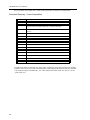
Introduction .............................................................................................................................1
Part Numbers .....................................................................................................................2
Start-up ..............................................................................................................................3
Mounting the LEGEND-MC to the LEGEND Amplifier ..........................................3
Mounting Orientation ............................................................................................3
Front Panel Description ..................................................................................................... 4
Power/Connections Wiring - Single Phase ........................................................................5
Power/Connections Wiring - Three Phase .........................................................................6
Cable Shielding, Segregation and Noise Immunity ...........................................................7
I/O Connections (50-pin CN5) ...........................................................................................8
Analog I/O ..........................................................................................................................9
Analog Input ..........................................................................................................9
Analog Output .....................................................................................................10
Digital I/O .........................................................................................................................11
Digital Input .........................................................................................................11
Digital Output .....................................................................................................12
Emergency Stop Chain ....................................................................................................13
Serial Communication ......................................................................................................14
External Encoder Specifications ......................................................................................15
Dedicated Inputs ..............................................................................................................16
Physical Specifications ....................................................................................................17
Hardware Specifications ..................................................................................................17
Cable Diagram and Dimensional Drawings .....................................................................18
I/O Cable with Terminal Block JUSP-TA50P ......................................................18
Theory of Operation .............................................................................................................21
Overview ..........................................................................................................................21
Level ................................................................................................................................22
Operation of Closed-Loop Systems .................................................................................24
System Modeling .............................................................................................................25
Controller ............................................................................................................25
Motor-Amplifier ...................................................................................................25
Current Drive ......................................................................................................25
Encoder ..............................................................................................................26
DAC ....................................................................................................................26
Digital Filter .........................................................................................................26
ZOH ....................................................................................................................27
System Analysis ..............................................................................................................27
System Design and Compensation .................................................................................30
The Analytical Method ........................................................................................30
Notch Filter .........................................................................................................32
Communications ..................................................................................................................37
Introduction ......................................................................................................................37
Controller Response to Data ..............................................................................37
RS232 Port .........................................................................................................37
SMC Protocol Guidelines .................................................................................................38
Ethernet Configuration .....................................................................................................39
Communication Protocols ...................................................................................39
Addressing ..........................................................................................................40
Ethernet Handles ................................................................................................40
Global vs. Local Operation .................................................................................41
Configuring Operation for Distributed Control
(Obsolete Method < 1.0c firmware) ....................................................................42
Operation of Distributed Control .........................................................................42
Accessing the I/O of the slaves ..........................................................................43
LEGEND-MC User’s Manual
4
Handling Communication Errors .........................................................................43
Modbus Support .................................................................................................43
Communicating with Multiple Devices ................................................................45
Multicasting .........................................................................................................45
Using Third Party Software .................................................................................45
Command Reference ............................................................................................................47
Command Description .....................................................................................................51
AB (Abort) ........................................................................................................................53
@ABS (Absolute Value) ..................................................................................................54
AC (Acceleration) .............................................................................................................55
@ACOS (Arc Cosine) ......................................................................................................56
AD (After Distance) ..........................................................................................................57
AF (Analog Feedback) .....................................................................................................58
AI (After Input) .................................................................................................................59
AL (Arm Latch) .................................................................................................................60
AM (After Motion) .............................................................................................................61
@AN (Analog Input) .........................................................................................................62
AO (Analog Out) ..............................................................................................................63
AP (After Absolute Position) ............................................................................................64
AR (After Relative) ...........................................................................................................65
AS (At Speed) ..................................................................................................................66
@ASIN (Arc Sine) ............................................................................................................67
AT (After Time) ................................................................................................................68
@ATAN (Arc Tangent) .....................................................................................................69
BG (Begin) .......................................................................................................................70
BL (Backward Limit) .........................................................................................................71
BN (Burn Parameters) .....................................................................................................72
BP (Burn Program) ..........................................................................................................73
BV (Burn Variables) .........................................................................................................74
CB (Clear Bit) ...................................................................................................................75
CD (Contour Data) ...........................................................................................................77
CE (Configure Encoder) ..................................................................................................78
CF (Configure Messages) ................................................................................................79
CH (Connect Handle) ......................................................................................................80
CM (Contour Mode) .........................................................................................................82
CN (Configure Limit Switches) .........................................................................................83
@COM (2’s Complement) ...............................................................................................84
@COS (Cosine) ...............................................................................................................85
CS (Clear Sequence) .......................................................................................................86
CW (Copyright) ................................................................................................................87
DA (De-allocate Variables) ..............................................................................................88
DB (Dynamic Brake) ........................................................................................................89
DC (Deceleration) ............................................................................................................90
DE (Dual (Auxiliary) Encoder) ..........................................................................................91
DL (Download) .................................................................................................................92
DM (Dimension Array) .....................................................................................................93
DP (Define Position) ........................................................................................................94
DT (Delta Time) ...............................................................................................................95
DV (Dual Velocity (Dual Loop)) ........................................................................................96
EA (ECAM Master) ..........................................................................................................97
EB (ECAM Enable) ..........................................................................................................98
EC (ECAM Counter) ........................................................................................................99
ED (Edit Mode) ..............................................................................................................100
EG (ECAM Engage) ......................................................................................................102
ELSE ..............................................................................................................................103
EM (ECAM Cycle) ..........................................................................................................104
LEGEND-MC User’s Manual
EN (End) ........................................................................................................................105
ENDIF ............................................................................................................................106
EO (Echo) ......................................................................................................................107
EP (ECam Table Intervals and Start Point) ...................................................................108
EQ (ECam Quit (Disengage)) ........................................................................................109
ER (Error Limit) ..............................................................................................................110
ET (ECam Table) ...........................................................................................................111
FA (Acceleration Feedforward) ......................................................................................112
FE (Find Edge) ..............................................................................................................113
FI (Find Index) ...............................................................................................................114
FL (Forward Limit) .........................................................................................................115
@FRAC (Fraction) .........................................................................................................116
FV (Velocity Feedforward) .............................................................................................117
GA (Master Axis for Gearing) ........................................................................................118
GR (Gear Ratio) .............................................................................................................119
HC (Handle Configuration) ............................................................................................120
HM (Home) ....................................................................................................................122
HR (Handle Restore) .....................................................................................................123
HS (Handle Switch) .......................................................................................................124
HW (Handle Wait) ..........................................................................................................125
HX (Halt Execution) .......................................................................................................126
IA (Internet Address) ......................................................................................................127
IF ....................................................................................................................................128
IH (Internet Handle) .......................................................................................................129
II (Input Interrupt) ...........................................................................................................131
IL (Integrator Limit) ........................................................................................................133
IN (Input Variable) ..........................................................................................................134
@IN (Input) ....................................................................................................................135
@INT (Integer) ...............................................................................................................137
IP (Increment Position) ..................................................................................................138
IT (Independent Time Constant) ....................................................................................139
JG (Jog) .........................................................................................................................140
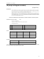
JP (Jump to Program Location) .....................................................................................141
JS (Jump to Subroutine) ................................................................................................142
KD (Derivative Constant) ...............................................................................................143
KI (Integrator) .................................................................................................................144
KP (Proportional Constant) ............................................................................................145
LA (List Arrays) ..............................................................................................................146
LC (Lock Controller) .......................................................................................................147
LE (Linear Interpolation End) .........................................................................................148
_LF* (Forward Limit) ......................................................................................................149
LI (Linear Interpolation) ..................................................................................................150
LL (List Labels) ..............................................................................................................152
LM (Linear Mode) ..........................................................................................................153
LO (Lockout) ..................................................................................................................154
_LR* (Reverse Limit) .....................................................................................................155
LS (List Program) ...........................................................................................................156
LT (Latch Target) ...........................................................................................................157
LV (List Variables) .........................................................................................................158
LZ (Leading Zeros) ........................................................................................................159
MB (Modbus) .................................................................................................................160
MC (Motion Complete) ...................................................................................................162
MF (Motion Forward) .....................................................................................................163
MG (Message) ...............................................................................................................164
MM (Master’s Modulus) .................................................................................................165
MO (Motor Off) ...............................................................................................................166
LEGEND-MC User’s Manual
MR (Motion Reverse) .....................................................................................................167
MT (Motor Type) ............................................................................................................168
MW (Modbus Wait) ........................................................................................................169
NA (Number of Axes) .....................................................................................................170
NB (Notch Bandwidth) ...................................................................................................171
NF (Notch Filter) ............................................................................................................172
NO (No Operation) .........................................................................................................173
NZ (Notch Zero) .............................................................................................................174
OB (Output Bit) ..............................................................................................................175
OC (Output Compare) ...................................................................................................176
OE (Off On Error) ...........................................................................................................177
OF (Offset) .....................................................................................................................178
OP (Output Port) ............................................................................................................179
@OUT (Output) .............................................................................................................180
PA (Position Absolute) ...................................................................................................181
PF (Position Format) ......................................................................................................182
PN (Legend Parameter) .................................................................................................184
PR (Position Relative) ....................................................................................................185
PW (Password) ..............................................................................................................186
QD (Download Array) ....................................................................................................187
QL (Query Latch - Auxiliary Encoder) ............................................................................188
QR (Data Record) ..........................................................................................................189
QU (Upload Array) .........................................................................................................190
QW (Slave Record Update Rate) ..................................................................................191
QZ (Return Data Record Information) ...........................................................................192
RA (Record Array) .........................................................................................................193
RC (Record) ...................................................................................................................194
RD (Record Data) ..........................................................................................................195
RE (Return from Error) ..................................................................................................197
RI (Return from Interrupt) ..............................................................................................198
RL (Report Latch) ..........................................................................................................199
@RND (Round) .............................................................................................................200
RP (Reference Position) ................................................................................................201
RS (Reset) .....................................................................................................................202
<control>R<control>S (Master Reset) ...........................................................................203
<control>R<control>V (Firmware Revision) ...................................................................204
SA (Send Command) .....................................................................................................205
SB (Set Bit) ....................................................................................................................206
SC (Stop Code) .............................................................................................................207
SH (Servo Here) ............................................................................................................208
@SIN (Sine) ...................................................................................................................209
SP (Speed) ....................................................................................................................210
@SQR (Square Root) ....................................................................................................211
ST (Stop) .......................................................................................................................212
TA (Tell Alarm) ...............................................................................................................213
TB (Tell Status Byte) ......................................................................................................214
TC (Tell Code) ...............................................................................................................215
TD (Tell Dual (Auxiliary) Encoder) .................................................................................218
TE (Tell Error) ................................................................................................................219
TH (Tell Handle) ............................................................................................................220
TI (Tell Inputs) ................................................................................................................221
TIME (Time Keyword) ....................................................................................................223
TL (Torque Limit) ...........................................................................................................224
TM (Time Base) .............................................................................................................225
TP (Tell Position) ...........................................................................................................226
TR (Trace Mode) ...........................................................................................................227
LEGEND-MC User’s Manual
5
6
TS (Tell Switches) ..........................................................................................................228
TT (Tell Torque) .............................................................................................................230
TV (Tell Velocity) ...........................................................................................................231
TW (Time Wait) ..............................................................................................................232
UL (Upload) ...................................................................................................................233
VA (Vector Acceleration) ...............................................................................................234
VD (Vector Deceleration) ...............................................................................................235
VE (Vector End) .............................................................................................................236
VF (Variable Format) .....................................................................................................237
VR (Vector Speed Ratio) ...............................................................................................238
VS (Vector Speed) .........................................................................................................239
VT (Vector Time Constant) ............................................................................................240
WC (Wait for Contour) ...................................................................................................241
WT (Wait) .......................................................................................................................242
XQ (Execute Program) ..................................................................................................243
ZS (Zero Subroutine Stack) ...........................................................................................244
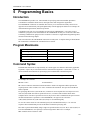
Programming Basics ..........................................................................................................249
Introduction ....................................................................................................................249
Program Maximums .......................................................................................................249
Command Syntax ..........................................................................................................249
Controller Response to Commands ...............................................................................251
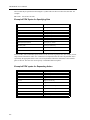
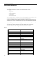
Command Summary ......................................................................................................252
Motion ...............................................................................................................252
Program Flow ...................................................................................................254
General Configuration .......................................................................................255
Control Filter Settings .......................................................................................256
Status ................................................................................................................256
Error And Limits ................................................................................................257
Arithmetic Functions .........................................................................................257
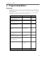
Programming Motion .........................................................................................................259
Overview ........................................................................................................................259
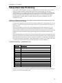
Independent Axis Positioning ........................................................................................261
Command Summary - Independent Axis ..........................................................261
Independent Jogging .....................................................................................................263
Command Summary - Jogging .........................................................................263
Linear Interpolation Mode ..............................................................................................264
Specifying Linear Segments .............................................................................264
Command Summary - Linear Interpolation .......................................................266
Vector Mode: Linear Interpolation Motion ......................................................................267
Specifying Vector Segments .............................................................................267
Additional Commands .......................................................................................267
Command Summary - Coordinated Motion Sequence .....................................268
Operand Summary - Coordinated Motion Sequence ........................................269
Electronic Gearing .........................................................................................................270
Command Summary - Electronic Gearing ........................................................270
Electronic Cam ..............................................................................................................271
Contour Mode ................................................................................................................275
Specifying Contour Segments ..........................................................................275
Additional Commands .......................................................................................276
Command Summary - Contour Mode ...............................................................276
General Velocity Profiles ..................................................................................276
Motion Smoothing ..........................................................................................................277
Using the IT and VT Commands (S curve profiling): ........................................277
Homing ..........................................................................................................................278
High Speed Position Capture (Latch Function) .............................................................279
LEGEND-MC User’s Manual
7
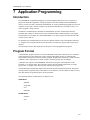
Application Programming ..................................................................................................281
Introduction ....................................................................................................................281
Program Format .............................................................................................................281
Special Labels ...............................................................................................................282
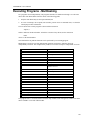
Executing Programs - Multitasking ................................................................................283
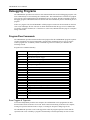
Debugging Programs .....................................................................................................284
Event Triggers & Trippoints ..............................................................................284
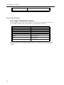
LEGEND-MC Event Triggers ............................................................................285
Event Trigger Examples: ..................................................................................286
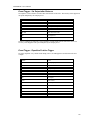
Conditional Jumps ............................................................................................289
Multiple Conditional Statements .......................................................................291
If, Else, and Endif ..............................................................................................293
Command Format - IF, ELSE and ENDIF ........................................................294
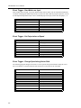
Subroutines .......................................................................................................295
Stack Manipulation ...........................................................................................296
Auto Start Routine ............................................................................................296
Automatic Subroutines for Monitoring Conditions .............................................296
Mathematical and Functional Expressions ....................................................................300
Variables ........................................................................................................................302
Programmable Variables ..................................................................................302
Internal Variables & Keywords ..........................................................................303
Arrays ............................................................................................................................306
Defining Arrays .................................................................................................306
Assignment of Array Entries .............................................................................306
Automatic Data Capture into Arrays .................................................................307
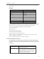
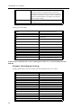
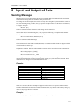
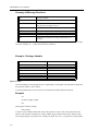
8 Input and Output of Data ...................................................................................................311
Sending Messages ........................................................................................................311
Input of Data .....................................................................................................312
Formatting Data ................................................................................................313
User Units .........................................................................................................315
9 Programmable I/O ...............................................................................................................317
Digital Outputs ...............................................................................................................317
Digital Inputs ..................................................................................................................318
10 Example Applications ........................................................................................................319
Instruction Set Examples ...............................................................................................319
Special Labels ..................................................................................................334
Wire Cutter ........................................................................................................338
Speed Control by Joystick ................................................................................339
Position Control by Joystick ..............................................................................340
Backlash Compensation by Dual-Loop .............................................................341
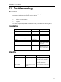
11 Troubleshooting .................................................................................................................343
Overview ........................................................................................................................343
Installation ......................................................................................................................343
Stability ..........................................................................................................................343
Operation .......................................................................................................................344
12 Index ....................................................................................................................................345
LEGEND-MC User’s Manual
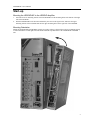
1 Introduction
The LEGEND-MC is a single axis Ethernet motion controller designed for use exclusively with Yaskawa’s LEGEND Digital Torque Amplifier.
It provides a structured text programming environment and the ability to perform many
modes of motion including camming, gearing, and contouring. High speed product registration is also available as a standard feature.
Additionally, point-to-point control and communications over the Ethernet connections
are standard features. The Ethernet function allows multiple handles or devices to communicate with the controller.
1
LEGEND-MC User’s Manual
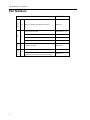
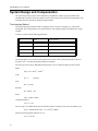
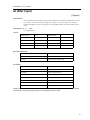
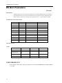
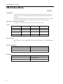
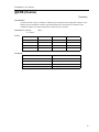
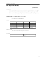
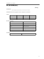
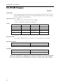
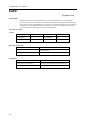
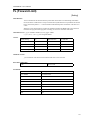
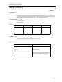
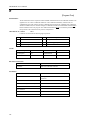
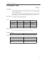
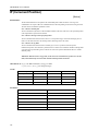
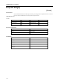
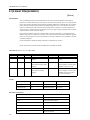
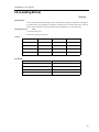
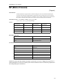
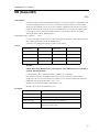
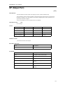
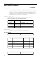
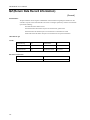
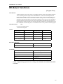
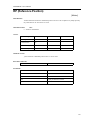
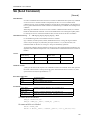
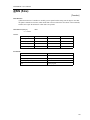
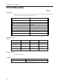
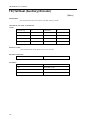
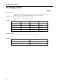
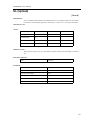
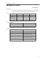
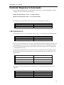
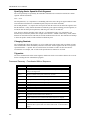
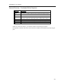
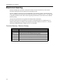
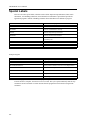
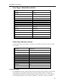
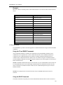
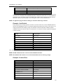
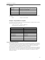
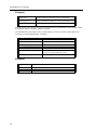
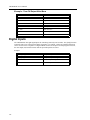
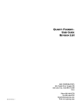
Part Numbers
Software
Serial
I/O
SMC3010
Description
2
a)
Part Number
Motion Controller with Ethernet Interface
SMC3010
1.0m 50 Pin I/O Cable
JZSP-CKI01-1 (A)
2.0m 50 Pin I/O Cable
JZSP-CKI01-2 (A)
3.0m 50 Pin I/O Cable
JZSP-CKI01-3 (A)
1.0m 50 Pin I/O Cable (with terminal block)
JUSP-TA50P
3.0m Port #1 Cable
SMCCBL7
YTerm Programming Software
SMCGUI1
SMC Comm serial + Ethernet driver for
application development for all SMC products
SMC0CX1
b)
c)
d)
LEGEND-MC User’s Manual
Start-up
Mounting the LEGEND-MC to the LEGEND Amplifier
1.
2.
Insert the lower two mounting notches of the LEGEND-MC into the mounting holes at the bottom of the right
side of the LEGEND.
Push the LEGEND-MC in the direction indicated by the arrow in the figure below, and insert the upper
mounting notches of the LEGEND-MC into the upper mounting holes on the right side of the LEGEND.
Mounting Orientation
Mount the LEGEND-MC and LEGEND vertically for proper cooling, as shown below. Allow a minimum spacing
of 10mm around the left and right sides and 30mm around the top and bottom of the LEGEND-MC/LEGEND
unit.
3
LEGEND-MC User’s Manual
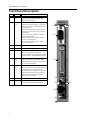
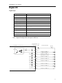
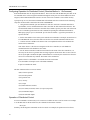
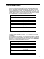
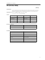
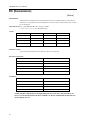
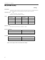
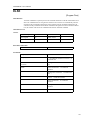
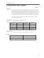
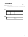
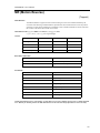
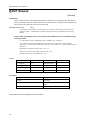
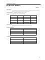
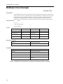
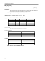
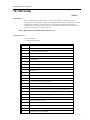
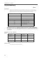
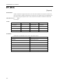
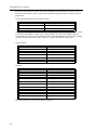
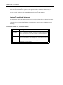
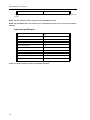
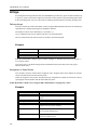
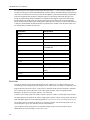
Front Panel Description
No.
Name
Description
(1)
Power
ON
A green LED that indicates +5 VDC power is
applied properly from the LEGEND-MC
amplifier to the controller.
(2)
Alarm/
Error
A red LED that will flash on initially at power
up and stay lit for approximately 1-8 seconds.
After power up, the LED will illuminate for the
following reasons:
•The axis has a position error greater than the
error limit. The error limit is set by using the
command ER.
•The reset line on the controller is held low or
is being affected by noise.
•There is a failure in the controller and the
processor is resetting itself.
•There is a failure in the output IC which
drives the error signal.
(3)
CN6
9 pin male D-Sub serial port connector
(4)
CN5
3M 50 pin high density I/O connector
(5)
RST
Reset switch. Causes the controller to reboot,
and load the application program and
parameters from flash. If the program contains
an #AUTO label, it will automatically execute.
(6)
Ethernet
status
A green LED that is lit when there is an
Ethernet connection to the controller. This
LED tests only for the physical connection, not
for an active or enabled link.
(7)
Ethernet
status
The yellow LED indicates traffic across the
Ethernet connection. This LED will show both
transmit and receive activity across the
connection. If there is no Ethernet connection
or IP address assigned, the LED will flash at
regular intervals to show that the BOOTP
packets are being broadcast.
(8)
CN4
10 BaseT Ethernet RJ485 Connector
(9)
FG
Frame ground spade terminal. Connect to
ground terminal on LEGEND Amplifier
(2)
(3)
(4)
(5)
(7)
(8)
(9)
4
(1)
(6)
LEGEND-MC User’s Manual
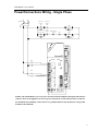
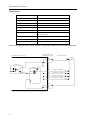
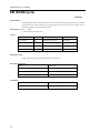
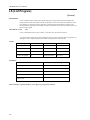
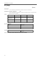
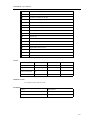
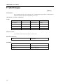
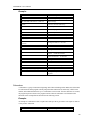
Power/Connections Wiring - Single Phase
R
T
1MCCB
Noise Filter
Control
Power
ON
Control
Power
OFF
1MC
Servo
Power
OFF
Servo ON
1MC
Emergency
Stop
SUP
1MC
2MC
2MC
SUP
YASKAWA
C
N
6
LEGEND01
2MC
CHARGE
POWER
L1
L2
L3
1
2
C
N
5
1MC
L1C
L2C
B1
B2
B3
U
V
W
C
N
1
C
N
2
R
S
T
C
N
4
F
G
NOTES: The LEGEND-MC receives its power from the LEGEND amplifier through the side interface
connector, however, the digital I/O receives its power from pins 46, 47, 48, and 49 on the I/O connector.
For maximum noise immunity, connect the FG to a ground terminal on the sub panel or to the ground
terminal on the LEGEND.
5
LEGEND-MC User’s Manual
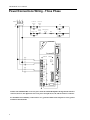
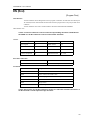
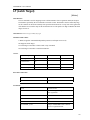
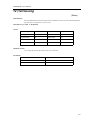
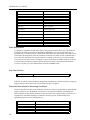
Power/Connections Wiring - Three Phase
R
S
T
1MCCB
Noise Filter
Control
Power
ON
Control
Power
OFF
1MC
Servo
Power
OFF
Servo ON
1MC
Emergency
Stop
SUP
1MC
2MC
2MC
SUP
YASKAWA
C
N
6
LEGEND01
2MC
CHARGE
POWER
L1
L2
L3
1
2
C
N
5
1MC
L1C
L2C
B1
B2
B3
U
V
W
C
N
1
C
N
2
R
S
T
C
N
4
F
G
NOTES: The LEGEND-MC receives its power from the LEGEND amplifier through the side interface
connector, however, the digital I/O receives its power from pins 46, 47, 48, and 49 on the I/O connector.
For maximum noise immunity, connect the FG to a ground terminal on the sub panel or to the ground
terminal on the LEGEND.
6
LEGEND-MC User’s Manual
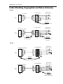
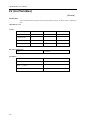
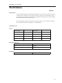
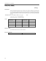
Cable Shielding, Segregation and Noise Immunity
Proper
SMC 3010
Terminal Block
Connector Case
Shields tied
back at device
a)
PROPER
Shield connected across
terminal block.
Terminal Block
Connector Case
Shields tied
back at device
b)
PROPER
Shield tied back at
terminal block.
PROPER
Shields of field
cables grounded at
one point
Wrong
Terminal Block
Shields tied
back at device
Terminal Block
Shields tied
back at device
Connector Case
a)
WRONG
Shield grounded at
more than one point.
Connector Case
b)
WRONG
Shields of field
cables ungrounded
7
LEGEND-MC User’s Manual
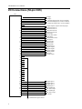
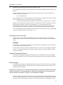
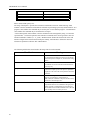
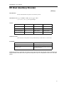
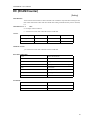
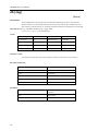
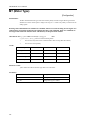
I/O Connections (50-pin CN5)
CN5
1
2
3
4
5
6
7
8
9
10
11
12
13
14
15
16
17
18
19
20
21
22
23
24
25
26
27
28
29
30
31
32
33
34
35
36
37
38
39
40
41
42
43
44
45
46
47
48
49
50
1
Analog 1
Analog 2
+5 Filtered Output power (60 mA available)
-12 Filtered Output power (10 mA available)
+12 Filtered Output power (10 mA available)
Output compare (requires internal jumper)
External encoder AExternal encoder A+
External encoder BExternal encoder B+
Abort Input
Reverse limit switch
Home Input
Forward limit switch
Reset Input
Digital Input 2
Digital Input 1
Digital Input 7
Digital Input 8
Digital Output 4
Digital Output 3
Digital Output 2
Digital Output 1
E STOP2
Analog Output
Digital Input 6
Digital Input 5
Digital Input 4
Digital Input 3
24V GND Input
24V Power Input
24V GND Input
24V Power Input
E STOP1
LEGEND-MC Signal Ground
8
LEGEND-MC User’s Manual
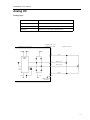
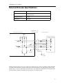
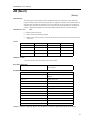
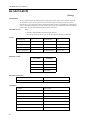
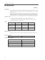
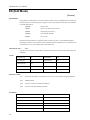
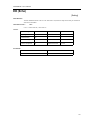
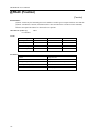
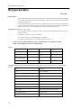
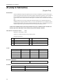
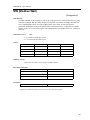
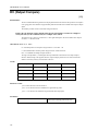
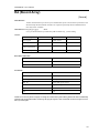
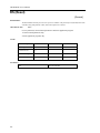
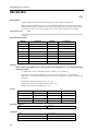
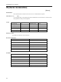
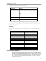
Analog I/O
Analog Input
Item
Specifications
Input Voltage
± 10 V
Input Impedance
Approximately 10k Ω
Resolution
14 bits over a ± 10V range or 4.88 mV per bit
Legend-MC I/O
Connector CN5
Internal Circuitry
12V
VCC
Field Wiring
12V
4
-12V
DG403
MUX
1
Analog 1
2
Analog 2
5
-12V
+12V
28
-12V
SMC Signal
Ground
9
LEGEND-MC User’s Manual
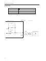
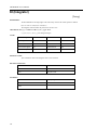
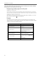
Analog Output
Item
Specifications
D/A Output Resolution
16 bit over a ± 10 V range or 328 µV/bit
Output short circuit duration
Infinite
Maximum output current
60 mA
Internal Circuitry
Legend-MC I/O
Connector CN5
Field Wiring
TL084CN
10
26
Analog
Output
External Device
-10 ~ 10 V
Signal
Ground
L
28
LEGEND-MC User’s Manual
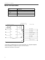
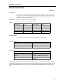
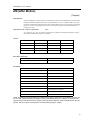
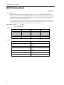
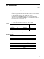
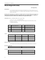
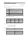
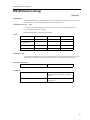
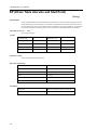
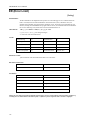
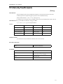
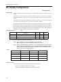
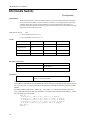
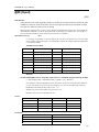
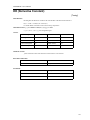
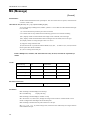
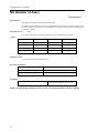
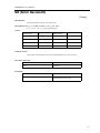
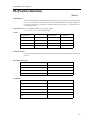
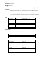
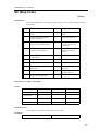
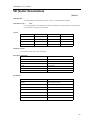
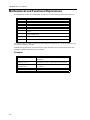
Digital I/O
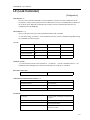
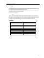
Digital Input
Item
Specifications
Number of Input Points
8
Input Format
Sinking
Isolation
Optical
Voltage
24 VDC ± 20%
Current Rating (ON)
5.3 mA to activate
Input Impedance
2.2k Ω
Operation Voltage
Logic 0 <5V
Logic 1 >15V
OFF Current
0.9 mA or less
Response Time
OFF to ON: <0.5 ms
ON to OFF: <1.5 ms
Latch response time
Less than 25 µsec
Minimum latch width
9 µsec
Note: Inputs float high unless the input is held low.
Legend-MC I/O
Connector CN5
Internal Circuitry
Field Wiring
24VDC
47
2.2k
49
18
45
Digital Input 1
(Main Latch)
Digital Input 2
(External Latch)
Digital Input 3
44
Digital Input 4
43
Digital Input 5
42
Digital Input 6
19
Digital Input 7
20
Digital Input 8
17
11
LEGEND-MC User’s Manual
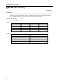
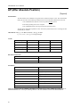
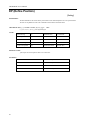
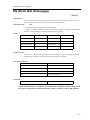
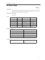
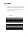
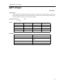
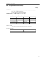
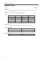
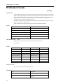
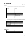
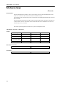
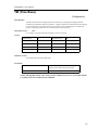
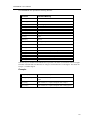
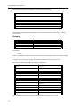
Digital Output
Item
Specifications
Number of Output Points
4
Output Format
Sinking
Output Classification
Transistor Output
Isolation
Optical
Load Voltage
24 VDC ± 20%
Load Current
200 mA/Output (600 mA if activated individually)
Response Time
OFF to ON <0.25 ms
ON to OFF <0.5 ms
External Common Power
24 VDC ± 20% 15 mA
Common User Fuse Rating
1A
Individual User Fuse Rating
200 mA recommended
NOTE: The ULN 2803 output chip is capable of 600 mA at a single output, or 800mA for the four outputs simultaneously.
Legend-MC I/O
Connector CN5
Internal Circuitry
Field Wiring
Fuse
47
4.7k
49
PS2505-4
ULN2803
24
Digital Output 1
23
Digital Output 2
22
Digital Output 3
21
Digital Output 4
10k
46
48
12
L
L
L
L
24VDC
LEGEND-MC User’s Manual
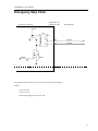
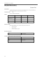
Emergency Stop Chain
Legend-MC I/O
Connector CN5
Internal Circuitry
Field Wiring
VCC
U17
50
E STOP1
25
E STOP2
Q1
-EROUT
2N7002
1k
The LEGEND-MC closes the relay contact under normal operating conditions.
Ratings:
1.0A @ 24 VDC
0.5A @ 125 VAC
Maximum switching power: 62.5VA, 30W
13
LEGEND-MC User’s Manual
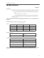
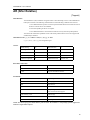
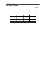
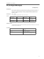
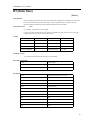
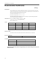
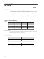
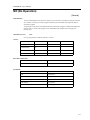
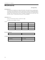
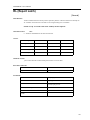
Serial Communication
Item
Specifications
Baud Rate
9600 or 19200 settable by jumper JP1, default is 19200
Data Bits
8
Parity
None
Stop Bits
1
Legend-MC Serial
Port Connector CN6
Internal Circuitry
U7
V+
C1+
.1 UF
C1C2+
.1 UF
C2T1IN
Field Wiring
VCC
.1 UF
VT1OUT
T2IN
T2OUT
A1IN
A1OUT
A2IN
A2OUT
MAX232A
.1 UF
1
CTS Output
6
CTS Output
8
CTS Output
2
Transmit Output
3
Receive Input
7
RTS Input
4
RTS Input
9
N/C
5
Signal Ground
NOTE: Hardware handshaking must be used with the LEGEND-MC. If it is impossible to implement
hardware handshaking, use a jumper between pins 1 and 4 in the connector.
NOTE: Do not connect pin 5 to a 24V ground.
14
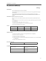
LEGEND-MC User’s Manual
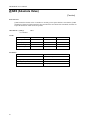
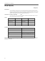
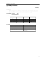
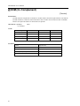
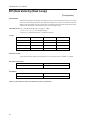
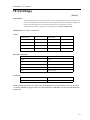
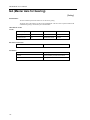
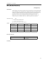
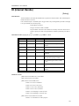
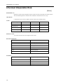
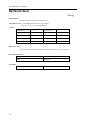
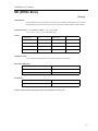
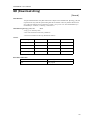
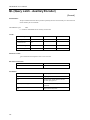
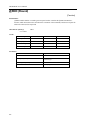
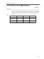
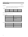
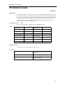
External Encoder Specifications
Item
Specifications
Input Format
Quadrature
Pulse and Direction
Maximum Frequency
12 MHz
Current Draw
940 µAmp
Legend-MC I/O
Connector CN5
Internal Circuitry
Field Wiring
VCC
6.8k
4.7k
6.8k
4.7k
External Encoder
+5V or +12V
9
A+phase
8
A-phase
3486
34
Digital
Ground
3486
0V
10
B-phase
11
B+phase
2.4k
2.4k
34
Digital
Ground
Shield
Frame
Ground
Standard voltage levels are TTL (0V to 5V), however, voltage levels up to 12V are acceptable. If using differential
12V signals, no modification is required. Single ended 12V signals require a bias voltage applied to the complimentary input, i.e.; use two 10k resistors, one connected to +12V and the other connected to the LEGEND signal
ground to hold the /A phase and /B phase at 6VDC. Do not use a 24VDC encoder.
15
LEGEND-MC User’s Manual
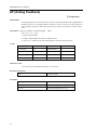
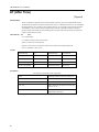
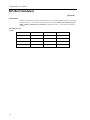
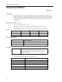
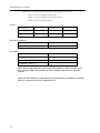
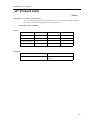
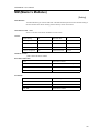
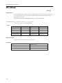
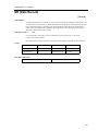
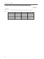
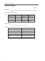
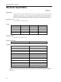
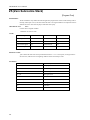
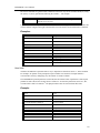
Dedicated Inputs
Item
Specifications
Number of Input Points
Forward limit, Reverse limit, Home, Abort, Reset
Input Format
Sinking
Isolation
Optical
Voltage
24 VDC ± 20%
Current Rating (ON)
5.3 mA to activate
Input Impedance
2.2k Ω
Operation Voltage
Logic 0 <5V
Logic 1 >15V
OFF Current
0.9 mA or less
Limit Switch Response Time
OFF to ON: <0.5 ms
ON to OFF: <1.5 ms
Legend-MC I/O
Connector CN5
Internal Circuitry
Field Wiring
24VDC
47
16
49
15
Forward Limit Switch
13
Reverse Limit Switch
14
Home Input
12
Abort Input
16
Reset Input
External Input Signal
2.2k
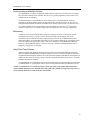
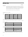
LEGEND-MC User’s Manual
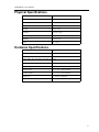
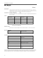
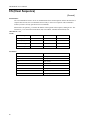
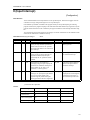
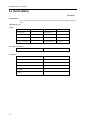
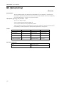
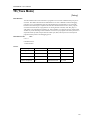
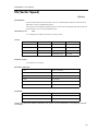
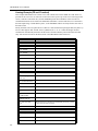
Physical Specifications
Description
Specifications
Depth:
130mm (5.12 in)
Width:
20 mm (.79 in)
Height:
142 mm (5.6 in)
Weight:
.18 kg (.4 lb.)
Vibration:
9.8 msec2 (1.0g)
Ambient temperature:
0 ~ 70° C (32 ~ 158° F)
Humidity:
Less than 95%
Noise:
IEC Level 3
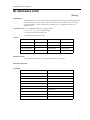
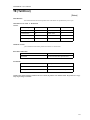
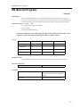
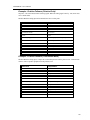
Hardware Specifications
Description
Specifications
CPU:
25 mHz Motorola
Servo update:
1000 µs default, 250 µs minimum
NOTE: Inputs float high unless the input is held low.
Digital inputs:
(8), +24VDC
Dedicated inputs:
(5), +24VDC
Digital Outputs:
(4), +24VDC
Analog inputs:
(2) +/- 10 V 12 bit resolution
Analog outputs:
(1) +/- 10 V 16 bit resolution
Serial port:
(1) 9600 or 19200 baud
Ethernet:
(1) 10-base-T
17
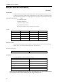
LEGEND-MC User’s Manual
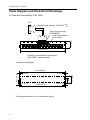
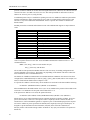
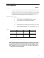
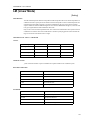
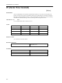
Cable Diagram and Dimensional Drawings
I/O Cable with Terminal Block JUSP-TA50P
CN5
+10%
Length of cable supplied: 19.69 (500) -0%
50-pin connector plug
MR-50RMD2
1
2
1.77 (45)
50-pin terminal block
M3.5 screws
49
50
9.74 (247.5)
Connector Terminal Block Converter Unit
JUSP-TA50P* (cable included)
Mounting Hole Diagram
0.14 (3.5)
0.27 (7.0)
10.28 (261.2)
*Terminal specifications: see I/O connections, page 8
18
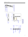
0.27 (7.0)
1.77 (45)
0.14 (3.5)
1.16
(29.5)
0.61 (15.5)
10.01 (254.2)
ETHERNET
ETHERNET LED'S
I/O
SERIAL PORT
F
G
R
S
T
C
N
4
C
N
5
C
N
6
GROUND
RESET
STATUS LED'S
(5.59)
ND MOUNTING
CLIP
20
142
(0.79)
(O.79)
DIMENSIONS: MM (IN)
APPROX. MASS: 0.18kg
MODEL NP
20
130
(5.12)
LEGEND MOUNTING
CLIP
CLIP ATTACHMENT TO LEGEND AM
SIDE PIN CONNECTOR
MOUNTING CLIPS
LEGEND-MC User’s Manual
19
LEGEND-MC User’s Manual
NOTES:
20
LEGEND-MC User’s Manual
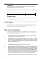
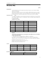
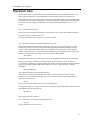
2 Theory of Operation
Overview
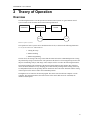
The following discussion covers the operation of motion control systems. A typical motion control
system consists of the elements shown in the following illustration:
COMPUTER
CONTROLLER
ENCODER
DRIVER
MOTOR
Elements of Servo Systems
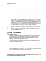
The operation of such a system can be divided into three levels, as shown in the following illustration
Levels of Control Functions. The levels are:
1. Closing the Loop
2. Motion Profiling
3. Motion Programming
The first level, the closing of the loop, assures that the motor follows the commanded position. Closing
the position loop using a sensor does this. The operation at the basic level of closing the loop involves the
subjects of modeling, analysis, and design. These subjects will be covered in the following discussions.
The motion profiling is the generation of the desired position function. This function, R(t), describes
where the motor should be at every sampling period. Note that the profiling and the closing of the loop
are independent functions. The profiling function determines where the motor should be and the closing
of the loop forces the motor to follow the commanded position
The highest level of control is the motion program. This can be stored in the host computer or in the
controller. This program describes the tasks in terms of the motors that need to be controlled, the
distances and the speed.
21
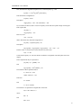
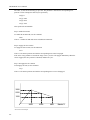
LEGEND-MC User’s Manual
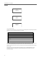
Level
LEVEL
3
MOTION
PROGRAMMING
2
MOTION
PROFILING
1
CLOSED-LOOP
CONTROL
Levels of Control Functions
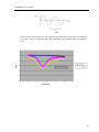
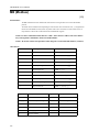
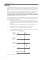
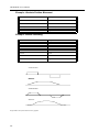
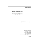
The three levels of control may be viewed as different levels of management. The top manager, the motion
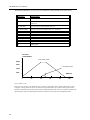
program, may specify the following instruction, for example.
PR 6000,4000
SP 20000,20000
AC 200000,300000
BG X
AD 2000
BG Y
EN
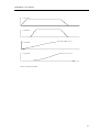
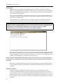
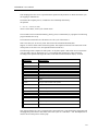
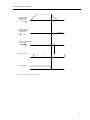
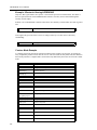
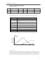
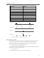
This program corresponds to the velocity profiles shown in the following illustration - Velocity and Position
Profiles. Note that the profiled positions show where the motors must be at any instant of time.
Finally, it remains up to the servo system to verify that the motor follows the profiled position by closing
the servo loop.
The operation of the servo system is done in two manners. First, it is explained qualitatively, in the
following section. Later, the explanation is repeated using analytical tools for those who are more
theoretically inclined.
22
LEGEND-MC User’s Manual
X VELOCITY
Y VELOCITY
X POSITION
Y POSITION
TIME
Velocity and Position Profiles
23
LEGEND-MC User’s Manual
Operation of Closed-Loop Systems
To understand the operation of a servo system, we may compare it to a familiar closed-loop operation,
adjusting the water temperature in the shower. One control objective is to keep the temperature at a
comfortable level, say 90 degrees F. To achieve that, our skin serves as a temperature sensor and reports to
the brain (controller). The brain compares the actual temperature, which is called the feedback signal, with
the desired level of 90 degrees F. The difference between the two levels is called the error signal. If the
feedback temperature is too low, the error is positive, and it triggers an action which raises the water
temperature until the temperature error is reduced sufficiently.
The closing of the servo loop is very similar. Suppose that we want the motor position to be at 90 degrees.
A position sensor, often an encoder, measures the motor position and the position feedback is sent to the
controller. Like the brain, the controller determines the position error, which is the difference between the
commanded position of 90 degrees and the position feedback. The controller then outputs a signal that is
proportional to the position error. This signal produces a proportional current in the motor, which causes a
motion until the error is reduced. Once the error becomes small, the resulting current will be too small to
overcome the friction, causing the motor to stop.
The analogy between adjusting the water temperature and closing the position loop carries further. We
have all learned that the hot water faucet should be turned at the "right" rate. If you turn it too slowly, the
temperature response will be slow, causing discomfort. Such a slow reaction is called overdamped
response.
The results may be worse if we turn the faucet too fast. The overreaction results in temperature
oscillations. When the response of the system oscillates, we say that the system is unstable. Clearly,
unstable responses are bad when we want a constant level.
What causes the oscillations? The basic cause for the instability is a combination of delayed reaction and
high gain. In the case of the temperature control, the delay is due to the water flowing in the pipes. When
the human reaction is too strong, the response becomes unstable.
Servo systems also become unstable if their gain is too high. The delay in servo systems is between the
application of the current and its effect on the position. Note that the current must be applied long enough
to cause a significant effect on the velocity, and the velocity change must last long enough to cause a
position change. This delay, when coupled with high gain, causes instability.
This motion controller includes a special filter that is designed to help the stability and accuracy.
Typically, such a filter produces, in addition to the proportional gain, damping and integrator. The
combination of the three functions is referred to as a PID filter.
The filter parameters are represented by the three constants KP, KI and KD, which correspond to the
proportional, integral and derivative term respectively.
The damping element of the filter acts as a predictor, thereby reducing the delay associated with the motor
response.
The integrator function, represented by the parameter KI, improves the system accuracy. With the KI
parameter, the motor does not stop until it reaches the desired position exactly, regardless of the level of
friction or opposing torque.
The integrator also reduces the system stability. Therefore, it can be used only when the loop is stable and
has a high gain.
The output of the filter is applied to a digital-to-analog converter (DAC). The resulting output signal in the
range between +10 and -10 Volts is then applied to the amplifier and the motor.
The motor position, whether rotary or linear is measured by a sensor. The resulting signal, called position
feedback, is returned to the controller for closing the loop.
The following section describes the operation in a detailed mathematical form, including modeling,
analysis and design.
24
LEGEND-MC User’s Manual
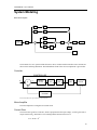
System Modeling
Basic Block Diagram
Acceleration
Acceleration
Feed Forward
[FA]
Speed
Velocity
Feed Forward
[FV]
+
+
Proportional
Gain
[KP]
+
+
Motion
Generator
[PA][PR][SP][AC]
[DC][JG][IP]
+
Scurve
Smoothing
[IT]
+
Derivative
Gain
[KD]
Notch Filter
[NF] [NB] [NZ]
+
+
Integral
Gain
[KI]
Torque Limit
[TL]
D/A
To Legend Amp
+
Integrator
Limit
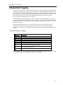
[IL]
Offset
[OF]
Encoder
Feedback
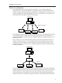
The elements of a servo system include the motor, driver, encoder and the controller. These elements are
shown in the following illustration. The mathematical model of the various components is given below:
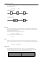
Controller
CONTROLLER
R
X
Σ
DIGITAL
FILTER
Y
ZOH
C
DAC
V
AMP
E
MOTOR
P
ENCODER
Functional Elements of a Motion Control System
Motor-Amplifier
The motor amplifier is configured for current mode:
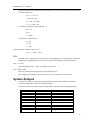
Current Drive
The current drive generates a current I, which is proportional to the input voltage, V, with a gain of Ka, a
torque constant of Kt, and inertia J. The resulting transfer function in this case is:
P/V = Ka Kt / Js2
25
LEGEND-MC User’s Manual
For example, a current amplifier with Ka = 2 A/V with the motor described by the previous example will
have the transfer function:
P/V = 1000/s2
[rad/V]
CURRENT SOURCE
I
V
Kt
JS
Ka
W
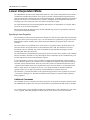
1
S
P
VELOCITY LOOP
V
1
Kg(ST 1+1)
W
1
S
P
Encoder
The encoder generates N pulses per revolution. It outputs two signals, Channel A and B, which are in
quadrature. Due to the quadrature relationship between the encoder channels, the position resolution is
increased to 4N quadrature counts/rev.
The model of the encoder can be represented by a gain of:
Kf = 4N/2π
[count/rad]
For example, a 1000 lines/rev encoder is modeled as:
Kf = 638
DAC
The DAC or D-to-A converter converts a 16-bit number to an analog voltage. The input range of the
numbers is 65536 and the output voltage range is +/-10V or 20V. Therefore, the effective gain of the DAC
is:
K= 20/65536 = 305 µVolt/count
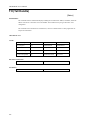
Digital Filter
The digital filter has a transfer function of D(z) = K(z-A)/z + Cz/z-1 and a sampling time of T.
The filter parameters, K, A and C are selected by the instructions KP, KD, KI or by GN, ZR and KI,
respectively. The relationship between the filter coefficients and the instructions are:
K = KP + KD
or K = GN
A = KD/(KP + KD)
or A = ZR
C = KI/8
26
LEGEND-MC User’s Manual
This filter includes a lead compensation and an integrator. It is equivalent to a continuous PID filter with
a transfer function G(s).
G(s) = P + sD + I/s
P = K(1-A) = KP
D = T* K * A = T.KD
I = C/T = KI/8 * TM
For example, if the filter parameters are KP = 4:
KD = 36
KI = 2
T = 0.001 s
the digital filter coefficients are:
K = 40
A = 0.9
C = 0.25
and the equivalent continuous filter, G(s), is:
G(s) = 4 + 0.036s + 250/s
ZOH
The ZOH, or zero-order-hold, represents the effect of the sampling process, where the motor command is
updated once per sampling period. The effect of the ZOH can be modeled by the transfer function
H(s) = 1/(1+sT/2)
If the sampling period is T = 0.001, for example, H(s) becomes:
H(s) = 2000/(s+2000)
However, in most applications, H(s) may be approximated as one.
This completes the modeling of the system elements. Next, we discuss the system analysis.
System Analysis
To analyze the system, we start with a block diagram model of the system elements. The analysis
procedure is illustrated in terms of the following example.
Consider a position control system with the LEGEND-MC controller and the following parameters:
Kt = 0.1
Nm/A
Torque constant
J = 2.10-4
kg.m2
System moment of inertia
R=2
W
Motor resistance
Ka = 4
Amp/Volt
Current amplifier gain
KP = 12.5
Digital filter gain
KD = 245
Digital filter zero
KI = 0
No integrator
27
LEGEND-MC User’s Manual
N = 500
Counts/rev
Encoder line density
T=1
ms
Sample period
The transfer function of the system elements are:
Motor:
M(s) = P/I = Kt/Js2 = 500/s2 [rad/A]
Amp:
Ka = 4 [Amp/V]
DAC:
Kd = 0.0012 [V/count]
Encoder:
Kf = 4N/2π = 318 [count/rad]
ZOH:
2000/(s+2000)
Digital Filter:
KP = 12.5, KD = 245, T = 0.001
Therefore,:
D(z) = 12.5 + 245 (1-z-1)
Accordingly, the coefficients of the continuous filter are:
P = 12.5
D = 0.245
The filter equation may be written in the continuous equivalent form:
G(s) = 12.5 + 0.245s = 0.245(s+51)
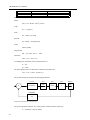
The system elements are shown in the following illustration:
Σ
FILTER
ZOH
DAC
AMP
MOTOR
0.245(S+51)
2000
S+2000
0.0012
4
500
S2
ENCODER
318
Mathematical model of the control system
The open loop transfer function, A(s), is the product of all the elements in the loop:
A = 390,000 (s+51)/[s2(s+2000)]
28
LEGEND-MC User’s Manual
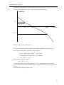
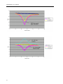
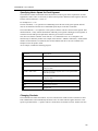
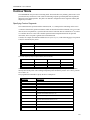
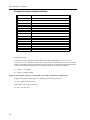
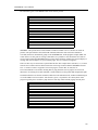
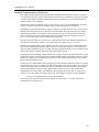
To analyze the system stability, determine the crossover frequency, ωc at which A(j ωc) equals one. This
can be done by the Bode plot of A(j ωc), as shown in the following illustration:
Magnitude
4
1
50
200
2000
W (rad/s)
0.1
Bode plot of the open loop transfer function
For the given example, the crossover frequency was computed numerically resulting in 200 rad/s.
Next, we determine the phase of A(s) at the crossover frequency:
A(j200) = 390,000 (j200+51)/[(j200)2 . (j200 + 2000)]
α = Arg[A(j200)] = tan-1(200/51)-180° -tan-1(200/2000)
α = 76° - 180° - 6° = -110°
Finally, the phase margin, PM, equals:
PM = 180° + α = 70°
As long as PM is positive, the system is stable. However, for a well damped system, PM should be
between 30 degrees and 45 degrees. The phase margin of 70 degrees given above indicated overdamped
response.
Next, we discuss the design of control systems.
29
LEGEND-MC User’s Manual
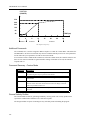
System Design and Compensation
The closed-loop control system can be stabilized by a digital filter, which is pre-programmed in the
LEGEND-MC controller. The filter parameters can be selected by the user for the best compensation. The
following discussion presents an analytical design method.
The Analytical Method
The analytical design method is aimed at closing the loop at a crossover frequency, ωc, with a phase
margin PM. The system parameters are assumed known. The design procedure is illustrated by a design
example.
Consider a system with the following parameters:
Kt
Nm/A
Torque constant
J = 2 * 10-4
kg.m2
System moment of inertia
R=2
W
Motor resistance
Ka = 2
Amp/Volt
Current amplifier gain
N = 1000
Counts/rev
Encoder line density
The DAC of the LEGEND-MC outputs +/-10V for a 14-bit command of +/-8192 counts.
The design objective is to select the filter parameters in order to close a position loop with a crossover
frequency of ωc = 500 rad/s and a phase margin of 45 degrees.
The first step is to develop a mathematical model of the system, as discussed in the previous system.
Motor:
M(s) = P/I = Kt/Js2 = 1000/s2
Amp:
Ka = 2
[Amp/V]
DAC
Kd = 10/8192:
Encoder:
Kf = 4N/2π = 636
ZOH:
H(s) = 2000/(s+2000)
Compensation Filter:
G(s) = P + sD
The next step is to combine all the system elements, with the exception of G(s), into one function, L(s):
SL(s) = M(s) Ka Kd Kf H(s) = 1.27*107/[s2(s+2000)]
Then the open loop transfer function, A(s), is:
A(s) = L(s) G(s)
30
LEGEND-MC User’s Manual
Now, determine the magnitude and phase of L(s) at the frequency ωc = 500:
L(j500) = 1.27*107/[(j500)2 (j500+2000)]
This function has a magnitude of:
|L(j500)| = 0.025
and a phase:
Arg[L(j500)] = -180° - tan-1(500/2000) = -194°
G(s) is selected so that A(s) has a crossover frequency of 500 rad/s and a phase margin of 45 degrees.
This requires that:
|A(j500)| = 1
Arg [A(j500)] = -135°
However, since:
A(s) = L(s) G(s)
then it follows that G(s) must have magnitude of:
|G(j500)| = |A(j500)/L(j500)| = 40
and a phase:
arg [G(j500)] = arg [A(j500)] - arg [L(j500)] = -135° + 194° = 59°
In other words, we need to select a filter function G(s) of the form:
G(s) = P + sD
so that at the frequency ωc =500, the function would have a magnitude of 40 and a phase lead of 59
degrees.
These requirements may be expressed as:
|G(j500)| = |P + (j500D)| = 40
and:
arg [G(j500)] = tan-1[500D/P] = 59°
The solution of these equations leads to:
P = 40cos 59° = 20.6
500D = 40sin 59° = 34.3
Therefore:
D = 0.0686
and:
G = 20.6 + 0.0686s
The function G is equivalent to a digital filter of the form:
D(z) = KP + KD(1-z-1)
where:
KP = P
and:
KD = D/T
31
LEGEND-MC User’s Manual
Assuming a sampling period of T=1ms, the parameters of the digital filter are:
KPX = 20.6
KDX = 68.6
The LEGEND-MC can be programmed with the instruction:
KP 20.6
KD 68.6
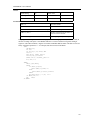
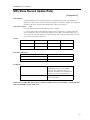
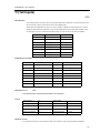
In a similar manner, other filters can be programmed. The procedure is simplified by the following table,
which summarizes the relationship between the various filters.
Digital
D(z) = K(z-A/z) + Cz/z-1
Digital
D(z) = KP + KD(1-z-1) + KI/8(1-z-1)
KP, KD, KI
K = KP + KD
A = KD/(KP+KD)
C = KI/8
Mathematical model of the motor and amplifier in two operational modes
Digital
D(z) = GN(z-ZR)/z + KI z/8(z-1)
GN, ZR, KI
K = GN
A = ZR
C = KI/8
Continuous
G(s) = P + Ds + I/s
PID, T
P = K(1-A) = KP
D = K *A * T = T * KD
I = C/T = KI / 8 * TM
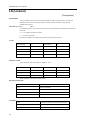
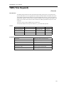
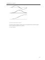
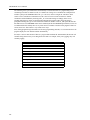
Notch Filter
There are some applications in which the standard tuning procedure using the PID filter of the controller
cannot completely eliminate the resonance in a system. Resonance occurs when the natural frequency of a
system is excited in a way that increases the amplitude of oscillation. This is usually due to system
compliance, such as a mechanical coupling or inherent motor characteristics.
The notch filter is an advanced tuning technique that acts much like a “band-reject” filter in an electronic
circuit. Certain frequencies are rejected while others are allowed to pass through. This is particularly
helpful when trying to eliminate a resonance that always occurs at a single frequency.
If a system oscillates at a specific point, then the first thing to do is find out at what frequency it occurs.
The easiest way to do this is to graph the Actual Motor Position versus Time while the motor is oscillating.
A sine wave with a constant frequency of oscillation should be seen. To get the frequency, f (Hertz), count
the number of peaks that occur in 1 second. Or alternatively, measure the distance between two peaks,
called the Period T (seconds), and then use the equation: f = 1/T.
32
LEGEND-MC User’s Manual
This will be the center frequency for your notch filter, specified as NF. To get the other two parameters,
it is easiest to look at an example that shows their relationship to the command output. See the graphs
below:
33
LEGEND-MC User’s Manual
34
LEGEND-MC User’s Manual
These graphs show how NF, NB, and NZ determine the characteristics of the filter. In particular, NB
specifies the bandwidth that is rejected (Figure 1). A larger NB causes a larger range of frequencies to be
attenuated. The ratio of NB/NZ controls the amount of attenuation, or depth of the notch (Figure 2). A
larger ratio causes a higher amount of attenuation. However, a ratio equal to one should have very little,
or no effect, on the output (Figure 3). A ratio greater than one will amplify the output signal (Figure 3)
causing a resonance. For consistency, these notch waveforms all have a center frequency of 25Hz, except
for the last one (Figure 4) which has a NF of 35 and is therefore shifted to the right.
A simple method for attaining your NF,NB, and NZ parameters is the following:
•Estimate resonance frequency.
•Set NF to resonance frequency in Hz.
•Set NB = 1/2 NF.
•Set NZ between zero and 5.
Although the theory behind a notch filter is beyond the scope of this application note, a general overview
may clarify how the notch works. As shown, the notch filter compensates for a resonance in the system.
One method of illustrating this is by looking at the poles and zeroes of the transfer function plotted on the
s-plane.
35
LEGEND-MC User’s Manual
Resonance shows up as a pair of complex poles with a real part. A notch filter attempts to cancel the
unwanted poles by placing zeroes on top of them and placing new poles in a more desirable location. The
following diagram shows the pole-zero configuration of a general system with resonance and a notch
filter:
A notch filter can be extremely helpful when used properly, however it is not right for every system.
Incorrect placement of the Notch can cause system instability, and a notch filter puts extra overhead on the
CPU of the controller. A general rule of thumb is to only use a notch when resonance has been found that
cannot be eliminated with the controller’s standard PID filter of the controller. Also, the notch filter is
only effective with a single resonant frequency.
36
LEGEND-MC User’s Manual
3 Communications
Introduction
The LEGEND-MC has one RS232 port and one Ethernet port. The RS-232 is a standard serial link with
communication baud rates up to 19.2kbaud. The Ethernet port is a 10Base-T link.
Controller Response to Data
Most LEGEND-MC instructions are represented by two characters followed by the appropriate
parameters. Each instruction must be terminated by a carriage return or semicolon.
Instructions are sent in ASCII, and the LEGEND-MC decodes each ASCII character (one byte) one at a
time. It takes approximately .5 msec for the controller to decode each command.
After the instruction is decoded, the LEGEND-MC returns a colon (:) if the instruction was valid or a
question mark (?) if the instruction was not valid or was not recognized.
For instructions requiring data, such at Tell Position (TP), the LEGEND-MC will return the data
followed by a carriage return, line feed and : .
It is good practice to check for : after each command is sent to prevent errors. An echo function is
provided to enable associating the LEGEND-MC response with the data sent. The echo is enabled by
sending the command EO 1 to the controller.
RS232 Port
The LEGEND-MC has a single RS232 connection for sending and receiving commands from a PC or
other terminal. The pin connections for the RS232 connection are as follows.
Port 1 DATATERM
1 RTS – input
6 RTS – input
2 Transmit Data - output
7 CTS – output
3 Receive Data - input
8 RTS – input
4 CTS – output
9 No connection (Can connect to +5V, 30mA) *
5 Ground
37
LEGEND-MC User’s Manual
Configuration
Although Yaskawa’s YTerm software automatically configures the port you may need to manually
configure the PC’s serial port if using third party software.
Configure your PC for 8-bit data, one start-bit, one stop-bit, full duplex and no parity. The baud rate for
the RS232 communication can be chosen by selecting the proper jumper configuration on the LEGENDMC according to the table below.
JP1-LOCATION “96” (JUMPER ATTACHED)
9600
JP1-LOCATION “96” (JUMPER UNATTACHED)
19200 (default)
Handshaking Modes
The RS232 port is configured for hardware handshaking. In this mode, the RTS and CTS lines are used.
The CTS line will go high whenever the LEGEND-MC is not ready to receive additional characters. The
RTS line will inhibit the LEGEND-MC from sending additional characters.
NOTE: The RTS line goes high for inhibit. This handshake procedure ensures proper communication especially at higher baud rates.
If a device that is used in conjunction with the LEGEND-MC does not support hardware handshaking,
solder a jumper across the CTS and RTS lines in the cable. Remember that doing so may degrade
communication reliability. Software handshake is not supported.
SMC Protocol Guidelines
The following items outline details of the simple ASCII communication protocol which the LEGENDMC implements. NOTE: throughout this section, strings are enclosed in single quotes, and characters are
enclosed in greater than / less than signs < >.
1)
Recommended method of querying variables: example `MG VAR<cr>' where MG is the message
command and VAR is a variable defined in the controller.
2)
Recommended methods of querying commands: example `MG _TPX<cr>' or `TPX <cr>' where MG
is the controller's message command and TP is the command to return the current position. For other
details, see the command section of an SMC manual. It describes the possible methods of obtaining
data when multiple axes are involved.
3)
Recommended method of setting a variable value: example `VAR=105<cr>'
4)
Recommended method of setting a command parameter: `PRX=12345<cr>' where PR is the Position
Relative command, "X" is the X axis, and the value assigned after the equal sign is the relative move
distance specified for the X axis. For other details, see the command section of an SMC manual. It
describes the possible methods of obtaining data when multiple axes are involved. Multiple axes can
be set at once. Example `PR 12345,6789<cr>' where PR is the Position Relative command, the first
value is assigned to the X axis and the second value is assigned to the Y axis. If an axis does not need
to be set, it can be omitted as follows: `PR ,,54321<cr>' which will set only the third (Z) axis.
5)
Hardware Handshaking is always recommended when communicating with the SMC family of con-
38
LEGEND-MC User’s Manual
trollers. It is the primary method used by the controller to synchronize communication with external
devices. The controllers do not support software handshaking, and simply using three-wire communication will result in possible character loss.
6)
When sending a command string of any kind to the controller, verify that the echo is active (EO1)
and matches the outgoing string before sending the carriage return. Compare the echo, then either
send the carriage return <cr> (if good) or send the backslash character <\> to flush the buffer in the
controller (if bad) then resend. Depending on the environment, retry the same string up to 3-5 times
before finally determining that there is a serious communication failure.
7)
When a message retry is required, send the backslash <\> character to flush the buffer in the SMC so
the next command string can be correctly understood. If the buffer contains a partial message, an
additional message could look like a bad message to the SMC, causing another '?<cr><lf>' .
8)
Do not use `VAR=<cr>' to request the SMC to return a variable value. If there was an error in transmission, and the string that the SMC received was not a variable that already exists in the controller,
it creates a new variable. If this happens enough times, the controller will fill its variable space. We
recommend using `MG VAR<cr>' which is more reliable, meaning if a bad transmission occurs, the
SMC will respond with a '?<cr><lf>', and not create an unwanted variable. NOTE: Use the 'LV<cr>'
(List Variables) command to see if there are any erroneous variables in the controller.
9)
Use the 'TC<cr>' command to get the error code if a question mark ever appears in a response string.
10)
Use of 'MG_TC<cr>' (Tell Code) and 'MG_ED<cr>' (The last line that had an error), which are set
when the #CMDERR routine executes.
Ethernet Configuration
Communication Protocols
The Ethernet is a local area network through which information is transferred in units known as packets.
Communication protocols are necessary to dictate how these packets are sent and received. The
LEGEND-MC supports two industry standard protocols, TCP/IP and UDP/IP. The controller will
automatically respond in the format in which it is contacted.
TCP/IP is a "connection" protocol. The master must be connected to the slave in order to begin
communicating. Each packet sent is acknowledged when received. If no acknowledgement is received,
the information is assumed lost and is resent.
Unlike TCP/IP, UDP/IP does not require a connection. This protocol is similar to communicating via
RS232. If information is lost, the controller does not return a colon or question mark. Because the
protocol does not provide for lost information, the sender must re-send the packet.
Although UDP/IP is more efficient and simple, Yaskawa recommends using the TCP/IP protocol. TCP/
IP insures that if a packet is lost or destroyed while in transit, it will be resent.
Ethernet communication transfers information in ‘packets’. The packets must be limited to 470 data bytes
or less. Larger packets could cause the controller to lose communication.
NOTE: To avoid losing information in transit, Yaskawa recommends that the user wait for an acknowledgement of receipt of a packet before sending the next packet.
NOTE: A command sent over an Ethernet Telnet session must reside in one packet. This means that a Telnet emulator must not send a command such as MG_TPX<CR> until the carriage return is present; i.e., do
not send one character at a time as the user enters them.
39
LEGEND-MC User’s Manual
Addressing
There are three levels of addresses defining Ethernet devices. The first is the Ethernet or hardware
address- a unique and permanent 6 byte number, or MAC address. No other device has the same Ethernet
address. The LEGEND-MC Ethernet address is set by the factory and the last two bytes of the address are
the serial number of the controller.
The second level of addressing is the IP address. This is a 32-bit (or 4 byte) number. The IP address is
constrained by each local network and must be assigned locally. Assigning an IP address to the controller
can be done in a number of ways.
The first method is to use the BOOT-P utility via the Ethernet connection (the LEGEND-MC must be
connected to the network and powered). For an explanation of BOOT-P see Third Party Software.
CAUTION: Be sure there is only one BOOT-P server running. If your network has DHCP or
BOOT-P running, it may automatically assign an IP address to the controller upon linking it to
the network. To ensure that the IP address is correct, please contact your system
administrator before connecting the controller to the Ethernet network.
PIC REQUIRED
The second method for setting an IP address is to send the IA command through the LEGEND-MC main
RS-232 port. The IP address you want to assign may be entered as a 4 byte number delimited by commas
(industry standard uses periods) or a signed 32 bit number. (Ex. IA 124,51,29,31 or IA 2083724575) Type
in BN to save the IP address to the controller's non-volatile memory.
NOTE: Yaskawa recommends that the IP address selected is not one that can be accessed across the Gateway. The Gateway is an application that controls communication between an internal network and the outside world.
The third level of Ethernet addressing is the UDP or TCP port number. The Yaskawa controller does not
require a specific port number. The port number is established by the master each time it connects to the
controller.
Ethernet Handles
An Ethernet handle is a communication resource within a device. The LEGEND-MC can have a
maximum of 16 Ethernet handles open at any time. When using TCP/IP, each connection to a device; i.e.,
the host computer, requires an individual Ethernet handle. In UDP/IP, one handle may be used for all the
masters, but each slave uses one. Pings and ARPS do not occupy handles. If all 8 handles are in use and a
9th master tries to connect, it will be sent a “reset packet” that generates the appropriate error in its native
application.
40
LEGEND-MC User’s Manual
Global vs. Local Operation
Each LEGEND-MC controls one axis of motion, referred to as A or X. The host computer can
communicate directly with any LEGEND-MC via an Ethernet or RS-232 connection. When the host
computer is directly communicating with any LEGEND-MC, all commands refer to the first axis as A or
X. Direct communication with the LEGEND-MC is known as “local operation”. The concept of Local
and Global Operation also applies to application programming.
Local Operation
Host Computer
Ethernet or RS 232
LEGEND-MC
X Axis
LEGEND-MC
X Axis
LEGEND-MC
X Axis
LEGEND-MC
X Axis
The LEGEND-MC supports Yaskawa’s control system. This allows up to four LEGEND-MC controllers
to be connected together as a single virtual axis controller. In this system, one of the controllers is
designated as the master. The master can receive commands from the host computer that apply to all of
the axes in the system.
Here is a simple way to view Local and Global Operation; when the host communicates with a slave
controller, it considers the slave as a 1 axis controller. When the host communicates with a master, it
considers the master as a multi-axis controller. Similarly, an application program residing in a slave
controller deals only with 1 motor as A or X. An application program in a master deals with all motors
referenced A through H.
Global Operation
Host Computer
LEGEND-MC
X Axis
Ethernet
LEGEND-MC
Y Axis
LEGEND-MC
Z Axis
LEGEND-MC
W Axis
The controllers may operate under both Local and Global Mode. In general, operating in Global Mode
simplifies controlling the entire system. However, Local Mode operation is necessary in some situations;
using Local Mode for setup and testing is useful since this isolates the controller. Specific modes of
motion require operation in Local Mode. Also, each controller can have a program including the slave
controllers. When a slave controller has a program, this program would always operate in Local Mode.
41
LEGEND-MC User’s Manual
Configuring Operation for Distributed Control (Obsolete Method < 1.0c firmware)
Each LEGEND-MC must be assigned an IP address. This can be done with the BOOT-P procedure or the
IA command can be used to assign the IP address through the serial port. Once the IP address has been
assigned, a BN command should be issued to save this value in the controller’s non-volatile memory.
Upon power-up or reset, the master LEGEND-MC will establish each slave connection. The following
steps must be taken while connected to the master LEGEND-MC:
1. Using the IH command, open two handles for each slave. Each slave controller must have 2
open handles, one for commands from the master, the other for data returned from the slave. The
second internet handle for each slave controller must contain a specific port value. The value must
be an even number greater than 502. The command for opening the communication handle is:
IHh=ip0,ip1,ip2,ip3<p>2 h is the handle. ip is the slave IP address. <p specifies port number. >2
specifies TCP/IP.
2. Set the total number of axes in the system with the NA command. For example, assume there are
two LEGEND-MC slaves, therefore there will be three axes and the command would be NA3.
3. Connect each slave handle to the master. This is accomplished with the CH command. The
format of this command is:
CHa=h1,h2 where a is the first axis designator of the slave controller, h1 is the handle for
commands and h2 is the handle for slave status.
4. For the master controller to make decisions based on the status of the slave controllers, it is
necessary for the slaves to generate data records giving their current status. The record is sent at a
rate set by the QW command. The QW command must be executed by the master before the slave
can issue a record under any method. The format of the command is:
QWh=n where h is the handle. n is a number between 4 and 16000.
n sets the number of samples (msec with default TM1000).
n equal to 0 disables the mode.
The data contained in the record is as follows:
• (RP) reference position
• (TP) encoder position
• (TE) position error
• (TV) velocity
• (TT) torque
• (TS) limit and home switches
• (TS) axis status (in motion, motor of, at speed, stopcode)
• (TI) uncommitted inputs
• (OP) uncommitted outputs
Operation of Distributed Control
For most commands it is unnecessary to be conscious of whether an axis is local or remote. For example,
to set the KP value for the X and Z axes, the command for the master would be:
KP 10,,20
Similarly, the interrogation commands can also be issued. For example, the position error for all axes
42
LEGEND-MC User’s Manual
would be TE. The position operand for the F axis would be _TPF.
Some commands are inherently sent to all controllers. These include commands such as AB (Abort), CN
and TM.
Certain commands need to be launched specifically. For this purpose there is the SA command. In its
simplest form the SA command is:
SAh=”command string”
Here “command string” will be sent to handle h. For example, the SA command is the means for sending
an XQ command to a slave. A more flexible form of the command is:
SAh=field1,field2,field3,field4...field8 Where each field can be a string in quotes or a variable.
When the master sends an SA command to a slave, it is possible for the master to determine the status of
the command. The response _IHh4 will return the number 1 to 4. One means waiting for the
acknowledgement from the slave. Two means a colon (command accepted) has been received. Three
means a question mark (command rejected) has been received. Four means the command timed out.
If a command generates responses (such as the TE command), the values will be stored in _SAh0 through
_SAh7. If a field is unused its _SA value will be -2^31.
Accessing the I/O of the slaves
The I/O of the slaves are settable and readable from the master. The bit numbers are adjusted by the
handle number of the data record. Each handle adds 100 to the bit number. Handle A is 100 and Handle F
is 600.
Example
Bit 2 on the slave using handle E for the data record would be 502. The arguments for SB, CB, and OB
use this format as does the @IN[ ] function.
For byte and word-wide I/O, use the SA command such as: SAC=”OP6” to set the output port of handle
C. SAC=”TI” will return the input port on handle C and the operand, _SAC0 will contain the response
from the TI command.
Handling Communication Errors
If a controller has an application program running and the TCP communication is lost, the #TCPERR
routine will automatically execute. See the Special Label Example program in the Example Applications
Modbus Support
The Modbus protocol supports communication between masters and slaves. The masters may be multiple
PC’s that send commands to the controller. The slaves are typically peripheral I/O devices that receive
commands from the controller.
NOTE: There are numerous ways to reset the controller; hardware reset (push reset button or power-down
controller) and software resets (through Ethernet or RS232 by entering RS). The only reset that will not
cause the controller to disconnect is a software reset via the Ethernet or RS232.
When the Yaskawa controller acts as the master, the IH command is used to assign handles and connect
to its slaves. The IP address may be entered as a 4 byte number separated with commas (industry standard
uses periods) or as a 32 bit number. A port may also be specified, but if not, it will default to 502. The
43
LEGEND-MC User’s Manual
protocol (TCP/IP or UDP/IP) to use must also be designated at this time, otherwise, the controller will not
connect to the slave. (Ex. IHB=151,25,255,9<179>2 This will open handle #2 and connect to the I/P
address 151.25.255.9, port 179, using TCP/IP).
An additional protocol layer is available for speaking to I/O devices. Modbus is an RS-485 protocol that
packages information in binary packets that are sent as part of a TCP/IP packet. In this protocol, each
slave has a 1 byte slave address.The LEGEND-MC can use a specific slave address or default to the
handle number.
Modbus protocol has commands called function codes. The LEGEND-MC supports 10 major function
codes:
Function Code
Definition
01
Read Coil Status (Read Bits)
02
Read Input Status (Read Bits)
03
Read Holding Registers (Read Words)
04
Read Input Registers (Read Words)
05
Force Single Coil (Write One Bit)
06
Preset Single Register (Write One Word)
07
Read Exception Status (Read Error Code)
15
Force Multiple Coils (Write Multiple Bits)
16
Preset Multiple Registers (Write Words)
17
Report Slave ID
The LEGEND-MC provides three levels of Modbus communication. The first level allows the user to
create a raw packet and receive raw data. It uses the MBh command with a function code of -1. The
command format is:
MBh=-1,len, array[ ] where len is the number of bytes
array [ ] is the array with the data
The second level incorporates the Modbus structure. This is necessary for sending configuration and
special commands to an I/O device. The formats vary depending on the function code that is called. For
more information, refer to Command Reference
The third level of Modbus communication uses standard Yaskawa commands. Once the slave has been
configured, the commands that may be used are @IN[ ], @AN[ ], SB, CB, OB, and AO. For example, AO
2020,8.2 would tell I/O number 2020 to output 8.2 volts.
If a specific slave address is not necessary, the I/O number to be used can be calculated with the following:
I/O Number= (HandleNum*1000)+((Module-1)*4)+(BitNum)
Where HandleNum is the handle number from 1 (A) to 16 (P). Module is the position of the module in the
rack from 1 to 16. BitNum is the I/O point in the module from 1 to 4.
If an explicit slave address is to be used, the equation becomes:
I/O Number=(SlaveAddress*1000)+(HandleNum*1000)+((Module-1)*4)+(Bitnum-1)
Which devices receive what information from the controller depends on a number of things. If a device
queries the controller, it will receive the response unless it explicitly tells the controller to send it to
another device. If the command that generates a response is part of a downloaded program, the response
will route to whichever port is specified as the default (unless explicitly told to go to another port). To
designate a specific destination for the information, add {Eh} to the end of the command. (Ex.
MG{EC}"Hello" will send the message "Hello" to handle #3. TP,,?{EF} will send the z axis position to
handle #6.)
44
LEGEND-MC User’s Manual
Communicating with Multiple Devices
The LEGEND-MC is capable of supporting multiple masters and slaves. The masters may be multiple
PC's that send commands to the controller. The slaves are typically peripheral I/O devices that receive
commands from the controller.
An Ethernet handle is a communication resource within a device. The LEGEND-MC can have a
maximum of 8 Ethernet handles open at any time. When using TCP/IP, each master or slave uses an
individual Ethernet handle. In UDP/IP, one handle may be used for all the masters, but each slave uses
one. (Pings and ARP's do not occupy handles.) If all 16 handles are in use and a 17th master tries to
connect, it will be sent a "reset packet" that generates the appropriate error in its native application.
Multicasting
A multicast is only used in UDP/IP and is similar to a broadcast (everyone on the network gets the
information) but specific to a group. As such, all devices within a specified group will receive
information sent in a multicast. The many multicast groups on a network are differentiated by their
multicast IP address. To communicate with all devices in a specific multicast group, information can be
sent to the multicast IP address rather than to each device IP address. All LEGEND-MC controllers
belong to a default multicast address of 239.255.19.56. The controller's multicast IP address can be
changed by using the IA> u command.
Using Third Party Software
Yaskawa supports ARP, BOOT-P, and Ping, which are utilities for establishing Ethernet connections.
ARP is an application that determines the MAC address of a device at a specific IP address. BOOT-P is
an application that determines which devices on the network do not have an IP address and assigns the IP
address you have chosen to it. Ping is used to check the communication between the device at a specific
IP address and the host computer.
The LEGEND-MC can communicate with a host computer through any application that can send TCP/IP
or UDP/IP packets. A good example of this is Telnet, a utility that comes with most Windows systems.
NOTE: A command sent over an Ethernet Telnet session must reside in one packet. This means that a
Telnet emulator must not send a command such as MG_TPX<CR> until the carriage return is present; i.e.,
do not send one character at a time as the user enters them.
45
LEGEND-MC User’s Manual
NOTES:
46
LEGEND-MC User’s Manual
4 Command Reference
AB (ABORT)
@ABS (ABSOLUTE VALUE)
AC (ACCELERATION)
@ACOS (ARC COSINE)
AD (AFTER DISTANCE)
AF (ANALOG FEEDBACK)
AI (AFTER INPUT)
AL (ARM LATCH)
AM (AFTER MOTION)
@AN (READ ANALOG)
AO (ANALOG OUTPUT)
AP (AFTER ABSOLUTE POSITION)
AR (AFTER RELATIVE DISTANCE)
AS (AT SPEED)
@ASIN (ARC SINE)
AT (AT TIME)
@ATAN (ARC TANGENT)
BG (BEGIN MOTION)
BL (REVERSE SOFTWARE LIMIT)
BN (BURN)
BP (BURN PROGRAM)
BV (BURN VARIABLES)
CB (CLEAR BIT)
CD (CONTOUR DATA)
CE (CONFIGURE ENCODER)
CF (CONFIGURE MESSAGES)
CH (CONNECT HANDLE)
CI (COMMUNICATION INTERRUPT)
CM (CONTOUR MODE)
CN (CONFIGURE LIMIT SWITCHES)
@COM (2’S COMPLEMENT)
@COS (COSINE)
CS (CLEAR SEQUENCE)
CW (COPYRIGHT INFORMATION / DATA ADJUSTMENT BIT ON/OFF)
DA (DE-ALLOCATE THE VARIABLES & ARRAYS)
DB (DYMANIC BRAKE)
DC (DECELERATION)
DE (DUAL (AUXILIARY) ENCODER POSITION)
DL (DOWNLOAD)
DM (DIMENSION)
DP (DEFINE POSITION)
DT (DELTA TIME)
DV (DUAL VELOCITY (DUAL LOOP))
EA (ECAM MASTER AXIS)
EB (ENABLE ECAM MODE)
47
LEGEND-MC User’s Manual
EC (ECAM COUNTER)
ED (EDIT)
EG (ECAM ENGAGE)
ELSE (ELSE FUNCTION FOR USE WITH IF CONDITIONAL STATEMENT)
EM (ECAM CYCLE)
EN (END)
ENDIF (END OF IF CONDITIONAL STATEMENT)
EO (ECHO)
EP (CAM TABLE INTERVALS AND STARTING POINT)
EQ (ECAM QUIT (DISENGAGE))
ER (ERROR LIMIT)
ET (ELECTRIC CAM TABLE)
FA (ACCELERATION FEED FORWARD)
FE (FIND EDGE)
FI (FIND INDEX)
FL (FORWARD SOFTWARE LIMIT)
@FRAC (FRACTION)
FV (VELOCITY FEED FORWARD)
GA (MASTER AXIS FOR GEARING)
GR (GEAR RATIO)
HC (HANDLE CONNECT)
HM (HOME)
HR (HANDLE RESTORE)
HS (HANDLE SWITCH)
HW (HANDLE WAIT)
HX (HALT EXECUTION)
IA (IP ADDRESS)
IF (IF CONDITIONAL STATEMENT)
IH OPEN INTERNET HANDLE)
II (INPUT INTERRUPT)
IL (INTEGRATOR LIMIT)
IN (INPUT VARIABLE)
@IN (STATUS OF DIGITAL INPUT)
@INT (INTEGER)
IP (INCREMENT POSITION)
IT (INDEPENDENT TIME CONSTANT - SMOOTHING FUNCTION)
JG (JOG)
JP (JUMP TO PROGRAM LOCATION)
JS (JUMP TO SUBROUTINE)
KD (DERIVATIVE CONSTANT)
KI (INTEGRATOR)
KP (PROPORTIONAL CONSTANT)
LA (LIST ARRAYS)
LC (LOCK CONTROLLER)
LE (LINEAR INTERPOLATION END)
LF (FORWARD LIMIT)
LI (LINEAR INTERPOLATION DISTANCE)
48
LEGEND-MC User’s Manual
LL (LIST LABELS)
LM (LINEAR INTERPOLATION MODE)
LO (LOCKOUT)
LR (REVERSE LIMIT)
LS (LIST PROGRAM)
LT (LATCH TARGET)
LV (LIST VARIABLES)
LZ (LEADING ZERO)
MB (MODBUS)
MC (MOTION COMPLETE - “IN POSITION”)
MF (FORWARD MOTION TO POSITION)
MG (MESSAGE)
MM (MASTER MODULUS)
MO (MOTOR OFF)
MR (REVERSE MOTION TO POSITION)
MT (MOTOR TYPE)
MW (MODBUS WAIT)
NA (NUMBER OF AXES)
NB (NOTCH BANDWIDTH)
NF (NOTCH FREQUENCY)
NO (NO OPERATION)
NZ (NOTCH ZERO)
OB (OUTPUT BIT)
OC (OUTPUT COMPARE)
OD (OUTPUT COMPARE - AUXILIARY ENCODER)
OE (OFF ON ERROR)
OF (OFFSET)
OP (OUTPUT PORT)
@OUT (STATUS OF DIGITAL OUTPUT)
PA (POSITION ABSOLUTE)
PF (POSITION FORMAT)
PR (POSITION RELATIVE)
PW (PASSWORD)
QD (DOWNLOAD ARRAY)
QL (REPORT LATCH - AUXILIARY ENCODER)
QR (DATA RECORD)
QU (UPLOAD ARRAY)
QW (SLAVE RECORD UPDATE RATE)
QZ (RETURN DATA RECORD INFORMATION)
RA (RECORD ARRAY)
RC (RECORD)
RD (RECORD DATA)
RE (RETURN FROM ERROR ROUTINE)
RI (RETURN FROM INTERRUPT ROUTINE)
RL (REPORT LATCHED POSITION)
@RND (ROUND)
RS (RESET)
49
LEGEND-MC User’s Manual
<CONTROL>R <CONTROL>S (MASTER RESET)
<CONTROL>R <CONTROL>V (REVISION INFORMATION)
SA (SEND COMMAND)
SB (SET BIT)
SC (STOP CODE)
SH (SERVO HERE)
@SIN (SIN)
SP (SPEED)
@SQR (SQUARE ROOT)
ST (STOP)
TB (TELL STATUS BYTE)
TC (TELL ERROR CODE)
TD (TELL DUAL ENCODER)
TE (TELL ERROR)
TH (TELL HANDLE)
TI (TELL INPUTS)
TIME (TIME OPERAND KEYWORD))
TL (TORQUE LIMIT)
TM (TIME COMMAND)
TP (TELL POSITION)
TR (TRACE)
TS (TELL SWITCHES)
TT (TELL TORQUE)
TV (TELL VELOCITY)
TW (TIMEOUT FOR IN POSITION (MC))
UL (UPLOAD)
VA (VECTOR ACCELERATION)
VD (VECTOR DECELERATION)
VE (VECTOR SEQUENCE END)
VF (VARIABLE FORMAT)
VR (VECTOR SPEED RATIO)
VS (VECTOR SPEED)
VT (VECTOR TIME CONSTANT)
WC (WAIT FOR CONTOUR DATA)
WT (WAIT)
XQ (EXECUTE PROGRAM)
ZS (ZERO SUBROUTINE STACK)
50
LEGEND-MC User’s Manual
Command Description
Each executable instruction is listed in the following section in alphabetical order.
The two letter op-code for each instruction is placed in the upper left corner. Below the op-code is a
description of the command and required arguments. As arguments, some commands require actual
values to be specified following the instruction. These commands are followed by lower case x, y, z, and
w. Values may be specified for any axis separately or any combination of axes. Axis values are separated
by commas. Examples of valid x,y, z, w syntax are listed below. For the SMC-3010, the axis designators
a,b,c,d,e,f,g,h are used where x,y,z,w can be used interchangeably with a,b,c,d.
Comment
Valid x,y,z,w syntax
AC x
Specify x only
AC x,y
Specify x and y only
AC x,,z
Specify x and z only
AC x,y,z,w
Specify x,y,z,w
AC ,y
Specify y only
AC ,y,z
Specify y and z
AC ,,z
Specify z only
AC ,,,w
Specify w only
AC x,,,w
Specify x and w only
AC a,,,d,,f
Specify a,d and f only
Where x, y, z and w are replaced by actual values.
A ? returns the specified value for that axis. For example, AC ?,?,?,?, returns the acceleration of the
X,Y,Z and W axes.
Other commands require action on the X,Y,Z or W axis to be specified. These commands are followed by
uppercase X,Y,Z or W. Action for a particular axis or any combination is specified by writing X,Y,Z or
W. No commas are needed. Valid XYZW syntax is listed below. The SMC-3010 uses ABCDEFGH axis
designators where XYZW can be used interchangeably with ABCD.
Valid XYZW syntax
Comment
SH X
Servo Here, X only
SH XYW
Servo Here, X,Y and W axes
SH XZW
Servo Here, X,Z and W axes
SH XYZW
Servo Here, X,Y,Z and W axes
SH Y
Servo Here, Y only
SH YZW
Servo Here, Y,Z and W axes
SH Z
Servo Here, Z only
SH
Servo Here, all axes
51
LEGEND-MC User’s Manual
SH W
Servo Here, W only
SH ZW
Servo Here, Z and W axes
SH ABFG
Servo Here, A,B,F,G axes
Where X,Y,Z and W specify axes.
The usage “Description:” specifies the restrictions on allowable execution. “While Moving” states
whether or not the command is valid while the controller is performing a previously defined motion. “In a
program” states whether the command may be used as part of a user-defined program. “Command Line”
states whether the command may be used from the serial port.
“Can be Interrogated” states whether or not the command can be interrogated by using ? to return the
specified value. “Used as an Operand” states whether a command can be used to generate a value for
another command or variable (i.e. V=_TTX). “Default Format” defines the format of the value with
number of digits before and after the decimal point. Finally, “Default Value” defines the values the
instruction’s parameters will have after a Master Reset.
The following table defines terms found in the usage chart for each command:
Classification
52
Meaning
All Axes
When this command is executed in the master, it causes
the command to be broadcast to all slaves in the distributed control system. Example CN, Limit Switch Configuration.
No, Local
These commands cannot be sent from a master to a slave
over Ethernet or are not involved with an Ethernet feature in any way.
QW packet
The information contained in this command is obtained
from the slave update packet. This packet is updated at
the QW rate. This is also the second parameter of the HC
command.
Specific Axis
If Ethernet is configured for Distributed Control, when a
slave axis is specified in a command such as
BLW=-5000, the command is relayed to the slave once,
and the slave acknowledges once.
Use SA
This command is possible over Ethernet, but only when
encapsulated inside an SA command to the appropriate
handle. Generally commands that have this listing are
not intended to be used with distributed control, but will
work normally when received by the slave.
LEGEND-MC User’s Manual
AB (Abort)
[Motion]
DESCRIPTION:
AB (Abort) stops motion instantly without controlled deceleration by freezing the profiler. If there is a
program executing, AB also aborts the program unless a 1 argument is specified. The command, AB, will
shut off the motors (disable the amplifier) for any axis in which the off-on-error function is enabled (see
command "OE"). AB aborts motion on all axes in motion and cannot stop individual axes. If a multi-axis
system is configured (distributed control) the AB command will abort all axes if issued to the master.
ARGUMENTS: AB n
where
n = 0 aborts motion and program
n = 1 aborts motion without aborting program
n = 2 aborts motion on all axes that are connected via ethernet, does not cause error for axes that have lost
connection.
USAGE:
While Moving
Yes
Default Value
n/a
In a Program
Yes
Default Format
n/a
Command Line
Yes
Can be Interrogated
Yes
Used as an Operand
Yes
Distributed Control
Out to all axes
OPERAND USAGE:
_AB returns the state of the Abort Input on the local controller.
RELATED COMMANDS:
"SH"
Turns servos back on if they were shut-off by
Abort and OE1.
EXAMPLES:
OE 0,0,0,0
Disable OFF/ON error for all axes
AB
Aborts motion unconditionally, motors remain
enabled
OE 1,1,1,1
Enable off-on-error
AB
Shuts off amplifier enable and aborts motion
#A
Label - Start of program
JG 20000
Specify jog speed on X-axis
BGX
Begin jog on X-axis
WT 5000
Wait 5000 msec
AB1
Abort motion without aborting program
WT 5000
Wait 5000 milliseconds
SH
Servo Here
JP #A
Jump to Label A
EN
End of the routine
NOTE: Use parameter 1 following AB if you want the motion to be aborted or application program will be aborted.
53
LEGEND-MC User’s Manual
@ABS (Absolute Value)
[Function]
DESCRIPTION:
@ABS returns the absolute value of a number or variable given in square brackets. Note that the @ABS
command is a function, which means that it does not follow the convention of the commands, and does not
require the underscore when used as an operand.
ARGUMENTS: @ABS [n]
where
n is a number
USAGE:
While Moving
Yes
Minimum n value
-2147483647.9999
In a Program
Yes
Maximum n value
2147483647.9999
Not in a program
Yes
Default Value
---
Can be Interrogated
No
Default Format
---
Used as an Operand
Yes
Distributed Control
No, Local
EXAMPLES:
54
OE 0,0,0,0
Program TEST
VAR1=-45.6
Set a variable equal to -45.6
MG @ABS[VAR1]
Display the absolute value of VAR1
VAR2=@ABS[VAR1]+100.404
Perform calculation
EN
End of program
LEGEND-MC User’s Manual
AC (Acceleration)
[Motion]
DESCRIPTION:
The Acceleration (AC) command sets the linear acceleration rate for independent moves, such as PR, PA
and JG moves. The parameters input will be rounded down to the nearest factor of 1024. The units of the
parameters are counts per second squared. The acceleration rate may be changed during motion. The DC
command is used to specify the deceleration rate.
ARGUMENTS: AC x, y, z, w or ACX=x or AC a,b, c, d, e, f, g, h where
x, y z, w, or a, b, c, d, e, f, g, h are unsigned integers
USAGE:
While Moving
Yes
Minimum Value
1024
In a Program
Yes
Maximum Value
67107840
Command Line
Yes
Default Value
256000
Can be Interrogated
Yes
Default Format
8.0
Used as an Operand
Yes
Distributed Control
Specific Axis
OPERAND USAGE:
_ACn contains the value of acceleration in counts/sec2 where n is an axis letter.
RELATED COMMANDS:
"DC"
Specifies deceleration rate.
"FA"
Feedforward Acceleration.
"IT"
Smoothing constant - S-curve
AC 150000
Set acceleration to 150000 counts/sec2
AC ?
Request the current acceleration setting
0149504
Returned Acceleration (resolution, 1024)
V=_ACX
Assigns the current acceleration setting to the
variable V
EXAMPLES:
NOTES: Specify realistic acceleration rates based on your physical system such as motor torque rating, loads, and amplifier
current rating. Specifying an excessive acceleration will cause large following error during acceleration and the motor will
not follow the commanded profile. The acceleration feedforward command FA will help minimize error during acceleration.
55
LEGEND-MC User’s Manual
@ACOS (Arc Cosine)
[Function]
DESCRIPTION:
@ACOS returns the arc cosine, in degrees, of a number or variable which is inserted in square brackets.
Note that the @ACOS command is a function, which means that it does not follow the convention of
other commands and does not require the underscore when used as an operand.
ARGUMENTS: @ACOS [n]
where
n is a number
USAGE:
While Moving
Yes
Minimum n value
-1
In a Program
Yes
Maximum n value
1
Not in a program
Yes
Default Value
---
Can be Interrogated
No
Default Format
---
Used as an Operand
Yes
Distributed Control
No, Local
EXAMPLES:
56
#TEST
Program TEST
VAR1=.707
Set a variable equal to .707
MG @ACOS[VAR1]
Display the absolute value of VAR1
VAR2=@ACOS[VAR1]+100.404
Perform calculation
EN
End of program
LEGEND-MC User’s Manual
AD (After Distance)
[Trippoint]
DESCRIPTION:
The After Distance (AD) command is a trippoint used to control the timing of events. This command will
hold up the execution of the following command until one of the following conditions have been met:
1. The commanded motor position crosses the specified relative distance from the start of the
move.
2. The motion profiling on the axis is complete.
3. The commanded motion is in the direction which moves away from the specified position.
The units of the command are quadrature counts. The motion profiler must be on or the trippoint will
automatically be satisfied.
NOTE: AD will be affected when motion smoothing time constant, IT, is not 1. See IT command for more
information.
ARGUMENTS: ADx, y, z, w or ADX=x or AD a,b, c, d, e, f, g, h where
x, y z, w, or a, b, c, d, e, f, g, h are unsigned integers
USAGE:
While Moving
Yes
Minimum Value
0
In a Program
Yes
Maximum Value
2147483647
Command Line
Yes
Default Value
---
Can be Interrogated
No
Default Format
---
Used as an Operand
No
Distributed Control
Specific Axis
RELATED COMMANDS:
"AR"
After Relative distance for sequential
triggering
“AP”
After Absolute Position
#A;DP0
Begin Program
PR 10000
Specify position
BG
Begin motion
AD 5000
Wait until profiler passes 5000 units from start
of move.
MG "Halfway" ;TP
Send message
EN
End Program
EXAMPLES:
NOTE: The AD command is accurate to the number of counts that occur in 2 msec. Multiply speed by 2 msec to obtain the
maximum position error in counts. Remember AD measures incremental distance from start of move on one axis.
57
LEGEND-MC User’s Manual
AF (Analog Feedback)
[Configuration]
DESCRIPTION:
The Analog Feedback (AF) command is used to set an axis with analog feedback instead of digital feedback
(quadrature/pulse dir). As the analog feedback is decoded by a 12-bit A/D converter, an input voltage of 10
volts is decoded as a position of 2047 counts and a voltage of -10 volts corresponds to a position of -2048
counts.
ARGUMENTS: AF x,y,z,w or AFX=x or AF a,b,c,d,e,f,g,h
where
x,y,z,w or a, b, c, d, e, f, g, h
1 = Enables analog feedback
0 = Disables analog feedback and switches to digital feedback
"?" returns a 0 or 1 which states whether analog feedback is enabled for the specified axes.
USAGE:
While Moving
No
Minimum Value
0
In a Program
Yes
Maximum Value
1
Command Line
Yes
Default Value
0
Can be Interrogated
Yes
Default Format
-
Used as an Operand
Yes
Distributed Control
Specific Axis
OPERAND USAGE:
_AFn returns the current feedback setting where n is an axis letter
RELATED COMMANDS:
"CE"
Configure Encoder
AF 1,0,0,1
Analog feedback on X and W axis
V1 = _AFX
Assign feedback type to variable
AF ?,?,?
Interrogate feedback type of X, Y, Z
EXAMPLES:
58
LEGEND-MC User’s Manual
AI (After Input)
[Trippoint]
DESCRIPTION:
The AI command is used in motion programs to wait until after the specified input condition has occurred.
If n is positive, it waits for the input to go high. If n is negative, it waits for n to go low. To wait for a
transition from high to low or low to high, put two AI commands together. AI is only available for local
inputs.
ARGUMENTS: AI +/-n
where
n is a signed integer
USAGE:
While Moving
Yes
Minimum Value
1
In a Program
Yes
Maximum Value
8
Command Line
Yes
Default Value
---
Can be Interrogated
No
Default Format
---
Used as an Operand
No
Distributed Control
No, Local
RELATED COMMANDS:
@IN[n]
Function to read digital input 1 through 8
"II"
Input interrupt
#ININT
Special label for input interrupt
#A
Begin Program
AI 7
Wait until input 7 is high
SP 10000
Speed is 10000 counts/sec
AC 20000
Acceleration is 20000 counts/sec2
PR 400
Specify position
BG
Begin motion
AI+ 7; AI- 7
Wait for falling edge on input 7
EN
End Program
EXAMPLES:
NOTE: The AI command actually halts execution until specified input is at desired logic level. Use the conditional Jump
command (JP) or input interrupt (II) if you do not want the program sequence to halt.
59
LEGEND-MC User’s Manual
AL (Arm Latch)
[Setting]
DESCRIPTION:
The AL command enables the latching function (high speed position capture) of the controller. When the
AL command is used to arm the position latch, the encoder position of the main encoder input will be
captured upon a low going signal on Input 1. When interrogated or used in an operand the AL command will
return a 1 if the latch is armed or a zero after the latch has occurred. The command RL returns the captured
position value. The CN command will change the polarity of the latch.
ARGUMENTS: ALn
where
n = XYZW or ABCDEFGH for the main encoder latch and
n = SX, SY, SZ, SW or SA, SB, SC, SD, SE, SF, SG, SH for the auxiliary encoder latch
USAGE:
While Moving
Yes
Minimum Value
n/a
In a Program
Yes
Maximum Value
n/a
Command Line
Yes
Default Value
n/a
Can be Interrogated
No
Default Format
n/a
Used as an Operand
Yes
Distributed Control
Specific Axis
OPERAND USAGE:
_ALn State
Meaning
0
Neither Armed
1
Main Armed
2
Auxiliary Armed
3
Both Armed
RELATED COMMANDS:
"RL"
Report Latch
"CN"
Configure
#START
Start program
ALX
Arm latch on X axis
JG 50000
Set up jog at 50000 counts/sec
BG
Begin the move
#LOOP
Loop until latch has occurred
EXAMPLES:
JP #LOOP,_ALX=1
60
RL
Transmit the latched position
EN
End of program
LEGEND-MC User’s Manual
AM (After Motion)
[Trippoint]
DESCRIPTION:
The AM command is a trippoint used to control timing of events. This command holds up execution of the
following commands until the current move on the specified axis or axes is completed. AM occurs when
the profiler is finished generating the last position command. However, the servo motor may not be in final
position. Use TE to verify position error for servos or use the MC trippoint to wait until final position is
reached by the servo.
ARGUMENTS: AM XYZWS or ABCDEFGH
where
X, Y, Z, W or A, B, C, D, E, F, G, H are axis designators. S indicates an interpolation sequence. No argument specifies that motion on all axes is complete.
USAGE:
While Moving
Yes
Minimum Value
n/a
In a Program
Yes
Maximum Value
n/a
Command Line
Yes
Default Value
---
Can be Interrogated
No
Default Format
---
Used as an Operand
No
Distributed Control
Specific Axis
RELATED COMMANDS:
"BG"
_BG returns a 0 if motion complete
“MC”
Actual Motion Complete
#MOVE
Start of program
PR 5000
Position relative move
BG
Begin motion
AM
Wait until motion is complete
EN
End of Program
#F;DP 0
Program F
PR 5000
Position relative move
BG
Begin motion
AM
Wait until motion is complete
MG "DONE";TP
Print message
EN
End of Program
EXAMPLES:
NOTE: AM command controls the timing between multiple move sequences. If the motor is in the middle of a position relative move (PR), a position absolute move (PA, BG) cannot be made until the first move is complete. Use AM to pause the
program sequences until the first motion is complete. AM tests for profile completion. Another testing method is to query the
operand, _BG. This is equal to 1 during motion, and 0 when motion profiling is complete.
61
LEGEND-MC User’s Manual
@AN (Analog Input)
[Function]
DESCRIPTION:
@AN returns the value of an analog input as a voltage (+/-10V). Note that the @AN command is a
function, which means that it does not follow the convention of other commands, and does not require the
underscore when used as an operand. The resolution is 14 bit, or 1.2mV per bit. To read analog inputs
from a slave controller, use the SA command.
When using this command to access I/O on a slave controller in distributed control mode, use it with the handle for
outbound master commands. Do not use the handle which is for incoming slave update packets. For example, if a
slave is connected on handles E and F, reference the I/O for the slave on handle E.
ARGUMENTS: @AN [n]
where
n is an unsigned integer
USAGE:
While Moving
Yes
Minimum n Value
1
In a Program
Yes
Maximum n Value
2
Not in a Program
Yes
Default n Value
n/a
Can be Interrogated
No
Default Format
10.4
Used as an Operand
Yes
Distributed Control
Use SA
EXAMPLES:
62
#TEST
Program TEST
MG @AN[2]
Display the value of analog input #2 as a
voltage
JGX=@AN[2]*10000
Set jog speed according to analog input
SAA=”MG @AN[2]”
Sends command MG @AN[2] to slave on
handle A
Analog3=_SAA
Returns slave response to SA command
BGX
Begin Move
EN
End of program
LEGEND-MC User’s Manual
AO (Analog Out)
[I/O]
DESCRIPTION:
The AO command sets the analog output voltage of the local analog output or ModBus devices connected
via Ethernet.
ARGUMENTS: AO m, n
where
m is either the local analog output voltage ranging from 9.9982 to -9.9982 or the I/O number calculated
using the following equations:
m = (SlaveAddress*1000) + (HandleNum*1000) + (Module-1)*4) + (Bitnum-1)
Slave Address is used when the ModBus device has slave devices connected to it and specified as
Addresses 0 to 225. Please note that the uses for ModBus are very rare and this number will usually be 0.
HandleNum is the handle specifier from A to P (1 - 16).
Module is the position of the module in the rack from 1 to 16.
BitNum is the I/O point in the module from 1 to 4.
n = the voltage which ranges from 9.9982 to –9.9982. If m is < 1000, n is omitted.
USAGE:
While Moving
Yes
Minimum n Value
-9.9982
In a Program
Yes
Maximum n Value
9.9982
Command Line
Yes
Default Value
n/a
Can be Interrogated
No
Default Format
---
Used as Operand
Yes, local only
Distributed Control
Use SA
OPERAND USAGE: _AO returns the value of the local analog output in volts.
RELATED COMMANDS:
"SB"
Set Bit
"CB"
Clear Bit
"MB"
Modbus
AO -3.4
Sets local analog output to -3.4V
AO 6016, 8.2
Sets analog output on modbus device on
handle F to 8.2V
SAA=”AO”,2.7
Set analog output of slave on handle A to 2.7V
SAA=”MG”,”_AO”
Send command MG_AO to slave controller on
handle A
VAR1=_SAA
Store the returned value to VAR1
EXAMPLES:
63
LEGEND-MC User’s Manual
AP (After Absolute Position)
[Trippoint]
DESCRIPTION:
The After Position (AP) command is a trippoint used to control the timing of events. This command will
hold up the execution of the following command until one of the following conditions have been met:
1. The commanded motor position crosses the specified absolute position.
2. The motion profiling on the axis is complete.
3. The commanded motion is moving away from the specified position.
The units of the command are quadrature counts. The motion profiler must be active or the trippoint will
automatically be satisfied.
ARGUMENTS: AP x, y, z, w or APX=x or AP a,b, c, d, e, f, g, h where
x, y z, w, or a, b, c, d, e, f, g, h are unsigned integers
USAGE:
While Moving
Yes
Minimum Value
-2147483648
In a Program
Yes
Maximum Value
2147483647
Command Line
Yes
Default Value
---
Can be Interrogated
No
Default Format
---
Used as an Operand
No
Distributed Control
Specific Axis
RELATED COMMANDS:
"AR"
Trippoint for relative distances
“AD”
After Distance
"MF"
Trippoint for forward motion
#TEST
Program B
DP0
Define position as zero
JG 1000
Set jog with speed of 1000 counts/sec
BG
Begin move
AP 2000
After passing position 2000
V1=_TP
Assign V1 the Xaxis X position
MG "Position is", V1
Print Message
ST
Stop axis
EN
End of Program
EXAMPLES:
NOTE: The accuracy of the AP command is the number of counts that occur in 2 msec. Multiply the speed by 2 msec to
obtain the maximum error. AP tests for absolute position. Use the AD command to measure incremental distances.
64
LEGEND-MC User’s Manual
AR (After Relative)
[Trippoint]
DESCRIPTION:
The After Relative (AR) command is a trippoint used to control the timing of events. This command will
hold up the execution of the following command until one of the following conditions have been met:
1. The commanded motor position crosses the specified relative distance from either the start of
the move or the last AR or AD command.
2. The motion profiling on the axis is complete.
3. The commanded motion is in the direction which moves away from the specified position.
The units of the command are quadrature counts. The motion profiler must be active or the trippoint will
automatically be satisfied.
ARGUMENTS: AR x, y, z, w or ARX=x or AR a, b, c, d, e, f, g, h where
x, y z, w, or a, b, c, d, e, f, g, h are unsigned integers
USAGE:
While Moving
Yes
Minimum Value
0
In a Program
Yes
Maximum Value
2147483647
Command Line
Yes
Default Value
---
Can be Interrogated
No
Default Format
---
Used as an Operand
No
Distributed Control
Specific Axis
RELATED COMMANDS:
“AD”
After Distance
"AP"
Trippoint for After absolute Position
“AR”
Trippoint for Relative Distance
#A;DP 0
Begin Program
JG 50000
Specify jog speed
BG
Begin motion
#B
Label
AR 5000
After passing 5000 counts of relative distance
on X-axis from the last trippoint
MG "Passed_X";TP
Send message
JP #B
Jump to Label #B
EN
End Program
EXAMPLES:
NOTE: AR is used to specify incremental distance from last AR or AD command. Use AR if multiple position trippoints are
needed in a single motion sequence.
65
LEGEND-MC User’s Manual
AS (At Speed)
[Trippoint]
DESCRIPTION:
The AS command is a trippoint that occurs when the generated motion profile has reached the specified
speed. This command will hold up execution of the following command until the speed is reached. The AS
command will operate after either accelerating or decelerating. If the commanded speed is not reached, the
trippoint will be triggered after the motion is stopped (after deceleration).
ARGUMENTS: AS XYZWS or ABCDEFGH
where
X, Y, Z, W or A, B, C, D, E, F, G, H are axis designators. S indicates an interpolation sequence. No argument specifies that motion on all axes is complete.
USAGE:
While Moving
Yes
Minimum Value
n/a
In a Program
Yes
Maximum Value
n/a
Command Line
Yes
Default Value
---
Can be Interrogated
No
Default Format
---
Used as an Operand
No
Distributed Control
Specific Axis
EXAMPLES:
#SPEED
Program A
PR 100000
Specify relative position
SP 10000
Specify speed
BG
Begin motion
AS
Wait until after commanded speed is reached
MG "At Speed"
Print Message
EN
End of Program
WARNING: The AS command applies to a trapezoidal velocity profile only with linear acceleration. AS used with S-curve
profiling may be inaccurate.
66
LEGEND-MC User’s Manual
@ASIN (Arc Sine)
[Function]
DESCRIPTION:
@ASIN returns the arc sine, in degrees, of a number or variable which is inserted in square brackets.
Note that the @ASIN command is a function, which means that it does not follow the convention of
other commands, and does not require the underscore when used as an operand.
ARGUMENTS: @ASIN [n]
where
n is an unsigned integer
USAGE:
While Moving
Yes
Minimum n value
-1
In a Program
Yes
Maximum n value
1
Not in a program
Yes
Default Value
---
Can be Interrogated
No
Default Format
---
Used as an Operand
Yes
Distributed Control
No, Local
EXAMPLES:
#TEST
Program TEST
MG @ASIN[VAR1]
Set variable
VAR1=.707
Display the arc sine of .707
VAR2=@ASIN[VAR1]+5
Perform calculation
EN
End of program
67
LEGEND-MC User’s Manual
AT (After Time)
[Trippoint]
DESCRIPTION:
The AT command is a trippoint which is used to hold up execution of the next command until after the
specified time has elapsed. The time is measured with respect to a defined reference time. AT 0 establishes
the initial reference. AT n specifies n msec from the reference. AT -n specifies n msec from the reference
and establishes a new reference after the elapsed time period. This command is useful for waiting an
accurate amount of time duration while still being able to perform some other operations as long as they
require less time than the AT time.
ARGUMENTS: AT n
where
n is a signed integer
n = 0 defines a reference time at current time
positive n waits n msec from reference
negative n waits n msec from reference and sets new reference after elapsed time period
(AT -n is equivalent to AT n; AT 0)
USAGE:
While Moving
Yes
Minimum Value
-2147483647
In a Program
Yes
Maximum Value
2147483647
Command Line
Yes
Default Value
---
Can be Interrogated
No
Default Format
---
Used as an Operand
No
Distributed Control
No, Local
EXAMPLES:
The following commands are sent sequentially:
68
AT 0
Establishes reference time 0 as current time
AT 50
Waits 50 msec from reference 0
AT 100
Waits 100 msec from reference 0
AT -150
Waits 150 msec from reference 0 and sets new
reference at 150
AT 80
Waits 80 msec from new reference (total
elapsed time is 230 msec)
LEGEND-MC User’s Manual
@ATAN (Arc Tangent)
[Function]
DESCRIPTION:
@TAN returns the arc tangent, in degrees, of a number or variable which is inserted in square brackets.
Note that the @ATAN command is a function, which means that it does not follow the convention of
other commands, and does not require the underscore when used as an operand.
ARGUMENTS: @ATAN [n]
where
n is an unsigned integer
USAGE:
While Moving
Yes
Minimum n value
-1
In a Program
Yes
Maximum n value
1
Not in a program
Yes
Default Value
---
Can be Interrogated
No
Default Format
---
Used as an Operand
Yes
Distributed Control
No, Local
EXAMPLES:
#TEST
Program TEST
MG @ATAN[VAR1]
Set variable
VAR1=.707
Display the arc sine of .707
VAR2=@ATAN[VAR1]+5
Perform calculation
EN
End of program
69
LEGEND-MC User’s Manual
BG (Begin)
[Motion]
DESCRIPTION:
The BG command starts motion. When used as an operand, the BG command will return a 1 if there is a
commanded motion in progress, a 0 otherwise. The BG command will result in a command error if a move
is already in progress, the servo is not enabled or a limit switch is preventing motion.
ARGUMENTS: BG XYZWS or ABCDEFGH
where
X, Y, Z, W, S or A, B, C, D, E, F, G, H specify the axis or sequence. No argument specifies that motion on
all axes is complete.
USAGE:
While Moving
No
Default Value
---
In a Program
Yes
Default Format
---
Command Line
Yes
Can be Interrogated
No
Used as an Operand
Yes
Distributed Control
Specific Axis
NOTE: BG, for a distributed control axis, forces the slave to send a QW packet immediately.
_BGn data comes from QW packet.
OPERAND USAGE:
_BGn contains a ‘0’ if motion complete on the axis, otherwise contains a ‘1’ where n is an axis letter.
RELATED COMMANDS:
"AM"
After motion complete
"ST"
Stop motion
PR 2000
Set up for a relative move
BG
Begin motion
AM
Wait until motion is complete
HM
Issue homing command
BG
Begin motion
AM
Wait until motion is complete
JG 1000
Issue jog command
BG
Begin motion
STATE=_BGX
Assign a 1 to STATE if the axis is performing
a move
EXAMPLES:
NOTE: You cannot give another BG command until current BG motion has been completed. Use the AM trippoint to wait
for motion complete between moves. Another method for checking motion complete is to test for _BG being equal to 0.
70
LEGEND-MC User’s Manual
BL (Backward Limit)
[Setting]
DESCRIPTION:
The BL command sets the reverse software limit. If this limit is exceeded during a commanded motion, the
motion will decelerate to a stop. Reverse motion beyond this limit is not permitted. The reverse limit is
activated at position n-1 count. To disable the reverse limit, set n to -2147483648. The units are in
quadrature counts.
ARGUMENTS: BLx, y, z, w or BLX=x or BL a, b, c, d, e, f, g, h where
x, y z, w, or a, b, c, d, e, f, g, h are signed integers
“?” returns the reverse software limit value
-2147483648 turns off the reverse limit.
USAGE:
While Moving
Yes
Minimum Value
-2147483648
In a Program
Yes
Maximum Value
2147483647
Command Line
Yes
Default Value
-2147483648
Can be Interrogated
Yes
Default Format
Position format
Used as an Operand
Yes
Distributed Control
Specific Axis
OPERAND USAGE:
_BLn contains the value of the reverse software limit where n is an axis letter.
RELATED COMMANDS:
EXAMPLES:
"FL"
Forward Limit
"PF"
Position Formatting
#TEST
Test Program
AC 1000000
Set Acceleration Rate
DC 1000000
Set Deceleration Rate
BL -15000
Set Reverse Limit
JG -5000
Jog Reverse
BG
Begin Motion
AM
After Motion (soft limit occurred)
TP
Tell Position
EN
End Program
71
LEGEND-MC User’s Manual
BN (Burn Parameters)
[General]
DESCRIPTION:
The BN command saves certain controller parameters in non-volatile EEPROM memory. This command
takes approximately one second to execute and must not be interrupted. If the burn is disrupted by power
failure, a memory checksum error will result. The controller returns a <:> when the Burn is complete.
PARAMETERS SAVED DURING BURN:
AC
EO
KI
OP
AF
EP
KP
PF
BL
ER
LZ
SB
ET (table)
MM
SP
CE
FA
MO (MOTOR OFF or ON) TL
CF
FL
MT
TM
CN
GA
NA
TR
CW
GR
NB
VA
DC
IA
NF
VD
DV
IL
NZ
VF
EA
IT
OE
VS
EM
KD
OF
VT
ARGUMENTS: None
USAGE:
While Moving
Yes
Default Value
---
In a Program
Yes
Default Format
---
Command Line
Yes
Can be Interrogated
No
Used as an Operand
Yes
Distributed Control
Use SA
VERY IMPORTANT!
Realize that the current values of the above parameters are saved in the EEPROM when the BN command
is executed.
72
LEGEND-MC User’s Manual
BP (Burn Program)
[General]
DESCRIPTION:
The BP command saves the application program in non-volatile EEPROM memory. This command
typically takes up to 10 seconds to execute and must not be interrupted. If the burn is disrupted by power
failure, a memory checksum error will result. The controller returns a <: >when the Burn is complete.
ARGUMENTS: None
USAGE:
While Moving
No
In a Program
No
Command Line
Yes
Can be Interrogated
No
Used as an Operand
No
Default Value
---
Distributed Control
Use SA
73
LEGEND-MC User’s Manual
BV (Burn Variables)
[General]
DESCRIPTION:
The BV command saves the defined variables and arrays in non-volatile EEPROM memory. This command
typically takes up to 2 seconds to execute and must not be interrupted. If the burn is disrupted by power
failure, a memory checksum error will result. The controller returns a <:> when the Burn variables are
complete.
ARGUMENTS: None
USAGE:
74
While Moving
No
In a Program
Yes
Command Line
Yes
Can be Interrogated
No
Used as an Operand
Yes
Default Value
---
Distributed Control
Use SA
LEGEND-MC User’s Manual
CB (Clear Bit)
[I/O]
DESCRIPTION:
The CB command clears a bit on the output port by setting it to logic zero. Slave controller or Modbus
outputs can be cleared also.
When using this command to access I/O on a slave controller in distributed control mode, use it with the
handle for outbound master commands. Do not use the handle which is for incoming slave update packets.
For example, if a slave is connected on handles E and F, reference the I/O for the slave on handle E.
ARGUMENTS: CB n
where
n is an integer corresponding to a specific output on the controller to be cleared (set to 0). The first output
on the controller is denoted as output 1. A LEGEND-MC controller has 4 digital outputs plus applicable I/
O connected by Modbus.
DISTRIBUTED CONTROL:
Handle
Command
Handle
Command
A
CB101 ~ CB104
I
CB901 ~ CB904
B
CB201 ~ CB204
J
CB1001 ~ CB1004
C
CB301 ~ CB304
K
CB1101 ~ CB1104
D
CB401 ~ CB404
L
CB1201 ~ CB1204
E
CB501 ~ CB504
M
CB1301 ~ CB1304
F
CB601 ~ CB604
N
CB1401 ~ CB1404
G
CB701 ~ CB704
O
CB1501 ~ CB1504
H
CB801 ~ CB804
P
CB1601 ~ CB1604
MODBUS:
NOTE: When using Modbus devices, the I/O points of the modbus devices are calculated
using the following formula:
n = (SlaveAddress*1000) + (HandleNum*1000) + ((Module-1)*4) + (Bitnum-1)
Slave Address is used when the ModBus device has slave devices connected to it and specified as
Addresses 0 to 255. The use of slave devices for modbus are very rare and this number will usually be 0.
HandleNum is the handle specifier from A to P (1 - 16).
Module is the position of the module in the rack from 1 to 16.
BitNum is the I/O point in the module from 1 to 4.
USAGE:
While Moving
Yes
Default Value
---
In a Program
Yes
Default Format
---
Command Line
Yes
Can be Interrogated
No
Used as an Operand
No
Distributed Control
Offset by 100
RELATED COMMANDS:
"SB"
"OP"
Set Bit
Define all outputs
75
LEGEND-MC User’s Manual
EXAMPLES:
76
CB 1
Clear output bit 1
CB 2
Clear output bit 2
CB 3
Clear output bit 3
CB 602
Clear output 2 on slave controller on handle F
CB 1505
Clear the fifth output on the SMC3010
connected on handle "O."
LEGEND-MC User’s Manual
CD (Contour Data)
[Motion]
DESCRIPTION:
The CD command specifies the incremental position for an arbitrary motion profile. The units of the
command are in quadrature counts. This command is only applicable in the Contour Mode (CM).
ARGUMENTS: CD x, y, z, w or CDX=x or CD a, b, c, d, e, f, g, h
where
x, y z, w, or a, b, c, d, e, f, g, h are signed integers
USAGE:
While Moving
Yes
Minimum Value
-32767
In a Program
Yes
Maximum Value
+32767
Command Line
Yes
Default Value
0
Can be Interrogated
No
Default Format
---
Used as an Operand
No
Distributed Control
No, Local
RELATED COMMANDS:
"CM"
Contour Mode
"WC"
Wait for Contour
"DT"
Time Increment
CM
Specify Contour Mode
DT 4
Specify time increment for contour mode
CD 200
Specify incremental positions of 200 counts
WC
Wait for complete
CD 100
New position data
WC
Wait for complete
DT0
Stop Contour
CD 0
Exit Mode
EXAMPLES:
77
LEGEND-MC User’s Manual
CE (Configure Encoder)
[Configuration]
DESCRIPTION:
The CE command configures the encoder inputs to the quadrature type or the pulse and direction type. It
also allows inverting the polarity. The configuration applies independently to the main axis encoder and the
auxiliary encoder inputs.
Warning: This command interacts with the CE command, which reverses the incoming encoder signals. Use
caution (motor off, machine estopped) when changing the MT or CE commands. If the two commands are
not in agreement with each other, the motor will run away at full speed when enabled.
ARGUMENTS: CE x, y, z, w or CEX=x or CE a, b, c, d, e, f, g, h where
x, y z, w, or a, b, c, d, e, f, g, h are unsigned integers
Each integer is the sum of two integers r and s which configure the main and the auxiliary encoders
according to the chart below.
“?” returns the encoder inputs
R=
MAIN ENCODER TYPE
S=
AUXILIARY ENCODER TYPE
0
Normal quadrature
0
Normal quadrature
4
Normal pulse and direction
8
Reversed quadrature
12
Reverse pulse and direction
2
Reversed quadrature
For example: CEX = 10 implies r = 2 and s = 8, both encoders are reversed quadrature.
USAGE:
While Moving
Yes
Minimum Value
0
In a Program
Yes
Maximum Value
10
Command Line
Yes
Default Value
0
Can be Interrogated
Yes
Default Format
2.0
Used as an Operand
Yes
Distributed Control
Specific Axis
OPERAND USAGE:
_CEn contains the value of encoder type for the main and auxiliary encoder where n is an axis letter.
RELATED COMMMANDS:
"MT"
Specify motor type
EXAMPLES:
78
CE 0
Configure encoders
CE ?
Interrogate configuration
V = _CE
Assign configuration to a variable
LEGEND-MC User’s Manual
CF (Configure Messages)
[Configuration]
DESCRIPTION:
Sets the controller’s default port for unsolicited messages. By default, the LEGEND-MC controller will
send unsolicited responses to the RS-232 serial port. An unsolicited message is one generated in the
controller, i.e.; a program fault message or a message resulting from the MG command with no port
designation specified.
ARGUMENTS:
CF n
where
n is A through P for Ethernet handles 1 thru 16, S for serial port.
USAGE:
While Moving
Yes
Default Value
83 (“S”)
In a Program
Yes
Default Format
Decimal
representation
Command Line
Yes
Distributed Control
Local Controller
OPERAND USAGE:
_CF will return the current port selected for unsolicited responses from the controller. The _CF will return
a decimal value of the ASCII code.
EXAMPLES:
CFA
Select Ethernet handle A to return unsolicited
responses.
MG_CF
Interrogate configuration
:65.000
Response from _CF showing handle A as
default port. 65 is the ASCII value for “A”.
79
LEGEND-MC User’s Manual
CH (Connect Handle)
[General]
DESCRIPTION:
The CH command is used to associate master and slave controllers in a distributed control system. The
master controller must associate one Ethernet handle for sending commands to each slave, and one Ethernet
handle for receiving status information from each slave. Note that these handles must first be opened before
assigning them with this command, see the command IH. This command is obsolete. Please use the HC
command instead.
ARGUMENTS: CHx=h1,h2
where
x is X, Y, Z, W or A, B, C, D, E, F, G, H.
h1 is the handle (character) to be used to send commands to the slave controller.
h2 is the handle (character) to be used for receiving status from the slave controller.
USAGE:
While Moving
Yes
Default Value
-
In a Program
Yes
Default Format
-
Command Line
Yes
Distributed Control
No, Local
RELATED COMMANDS:
“IH”
Set Internet Handles
“NA”
Set Number of Axes for Distributed Control System
“QW”
Set Slave Data record Update Rate
EXAMPLE:
CHY=A,B
Using one LEGEND-MC as a master and one LEGEND-MC as a slave
under TCP/IP. This command assigns a slave, identified by the Y axis
designator, with Handle A for commands and Handle B for status
returned from the slave.
An example subroutine demonstrating how to release handles:
80
#RELEASE
Release handles
MG "Releasing..."
Diagnostic message
IHE=>-2
Release handle E
#WAIT; JP #WAIT,_IHE2<>0
Wait until handle is released
IHF=>-2
Release handle
#WAIT1; JP #WAIT1,_IHF2<>0
Wait until handle is released
EN
End subroutine
LEGEND-MC User’s Manual
An example subroutine demonstrating how to assign handles:
#ASSIGN
Assign handles
MG "Assigning..."
Diagnostic message
IHE=192,168,3,104>2
Must let first IH command succeed before setting another IH
#WAITA; JP #WAITA,_IHE2<>-2
Wait until handle is connected
IHF=192,168,3,104<504>2
Assign response handle to slave
#WAITB; JP #WAITB,_IHF2<>-2
Wait until handle is connected
EN
End subroutine
An example subroutine demonstrating how to connect handles:
#CONNECT
Connect to slave
MG "Connecting..."
Diagnostic message
NA2
Set two axis configuration
CHY=E,F
Connect the handles
QWF=4
Set slave response update (don’t need to set QW for commands on handle A)
EN
End subroutine
81
LEGEND-MC User’s Manual
CM (Contour Mode)
[Setting]
DESCRIPTION:
The Contour Mode is initiated by the instruction CM. This mode allows the generation of an arbitrary
motion trajectory. The CD command specifies the position increment, and the DT command specifies the
time interval.
The CM? or _CM commands can be used to check the status of the Contour Buffer. A value of 1 returned
indicates that the Contour Buffer is full. A value of 0 indicates that the Contour Buffer is empty.
ARGUMENTS: CM XYZW or ABCDEFGH
CM? Returns a 1 if the contour buffer is full, and 0 if the contour buffer is empty.
USAGE:
While Moving
No
Default Value
---
In a Program
No
Default Format
1.0
Command Line
Yes
Can be Interrogated
No
Used as an Operand
Yes
Distributed Control
No
OPERAND USAGE:
_CM contains a ‘0’ if the contour buffer is empty, otherwise contains a ‘1’ meaning the buffer is
full.
RELATED COMMANDS:
"CD"
Contour Data
"WC"
Wait for Contour
"DT"
Time Increment
V=_CM;V=
Return Contour Buffer Status
1
Contour Buffer is full
CM
Specify Contour Mode
EXAMPLES:
82
LEGEND-MC User’s Manual
CN (Configure Limit Switches)
[Configuration]
DESCRIPTION:
The CN command configures the polarity of the limit switches, the home switch and the latch input.
ARGUMENTS: CN m,n,o
where
m, n, o are integers .
m=
n=
o=
1
Limit switches active high
-1
Limit switches active low
1
Home switch configured to drive motor in forward direction when input is high
upon initial HM execution. See HM and FE commands
-1
Home switch configured to drive motor in reverse direction when input is high
upon initial HM execution. See HM and FE commands
1*
Latch input is active high
-1
Latch input is active low
*
NOTE: The latch function will occur within 25usec only when used in active low mode, the opto
isolator requires more time if active high.
USAGE:
While Moving
Yes
Default Value
-1.-1.-1
In a Program
Yes
Default Format
2.0
Command Line
Yes
Can be Interrogated
No
Used as an Operand
Yes
Distributed Control
All Axes
OPERAND USAGE:
_CN0 Contains the limit switch configuration.
_CN1 Contains the home switch configuration.
_CN2 Contains the latch input configuration.
RELATED COMMANDS:
"MT"
Motor Type
CN 1,1
Sets limit and home switches to active high
CN, -1
Sets input latch active low
MG_CN1
Returns Home input configuration
MG_CN2
Returns Latch input configuration
EXAMPLES:
83
LEGEND-MC User’s Manual
@COM (2’s Complement)
[Function]
DESCRIPTION:
@COM returns the complement of a number or variable which is inserted in square brackets. Note that the
@COM command is a function, which means that it does not follow the convention of other commands,
and does not require the underscore when used as an operand.
ARGUMENTS: @COM [n]
where
n is a number
USAGE:
While Moving
Yes
Minimum n value
-2147483647.9999
In a Program
Yes
Maximum n value
2147483647.9999
Not in a program
Yes
Default Value
---
Can be Interrogated
No
Default Format
---
Used as an Operand
Yes
Distributed Control
No, Local
EXAMPLES:
84
#TEST
Program TEST
VAR1=1234
Set variable
MG @COM[VAR1]
Display the complement of 1234
VAR2=@COM[VAR1]+99
Perform calculation
EN
End of program
LEGEND-MC User’s Manual
@COS (Cosine)
[Function]
DESCRIPTION:
@COS returns the cosine of a number or variable given in square brackets using units of degrees. Note
that the @COS command is a function, which means that it does not follow the convention of the
commands, and does not require the underscore when used as an operand.
ARGUMENTS: @COS [n]
where
n is a number
USAGE:
While Moving
Yes
Minimum n value
-32768
In a Program
Yes
Maximum n value
32768
Not in a program
Yes
Default Value
---
Can be Interrogated
No
Default Format
---
Used as an Operand
Yes
Distributed Control
No, Local
EXAMPLES:
#TEST
Program TEST
VAR1=60
Set variable
MG @COS[VAR1]
Display the value of the sine of VAR1
VAR2=@COS[VAR1]+9
Perform calculation
EN
End of program
85
LEGEND-MC User’s Manual
CS (Clear Sequence)
[General]
DESCRIPTION:
The CS command will remove VP or LI commands stored in a motion sequence. Please note that after a
sequence has been run, the CS command is not necessary to enter a new sequence. This command is
useful if you have correctly specified VP or LI commands.
When used as an operand, _CS returns the number of the segment in the sequence, starting at zero. The
instruction _CS is valid in the Linear Mode, LM, Vector Mode, VM and Contour Mode, CM .
ARGUMENTS: none
USAGE:
While Moving
No
Default Value
---
In a Program
Yes
Default Format
---
Not in a program
Yes
Can be Interrogated
No
Used as an Operand
Yes
Distributed Control
No, Local
EXAMPLES:
86
#CLEAR
Label
VP 1000,2000
Vector position
VP 4000,8000
Vector position
CS
Clear vectors
VP 1000,5000
New vector
VP 8000,9000
New vector
VE
End sequence
BGS
Begin motion sequence
EN
End of program
LEGEND-MC User’s Manual
CW (Copyright)
[General]
DESCRIPTION:
The CW command has a dual usage. The CW command will return the copyright information when the
argument, n is 0. Otherwise, the CW command is used as a communications enhancement. When CW = 1,
the communication enhancement sets the MSB of unsolicited, returned ASCII characters to 1. Unsolicited
ASCII characters are those characters which are returned from the controller without being directly queried
from an external source. This is the case when a program has a command that requires the controller to
return a value or string. The benefit of this is that two-way unsolicited messages can be filtered by an
external source to retrieve answers to strings that were sent by the external source.
ARGUMENTS: CW n,m
where
n is a number, either 0,1 or 2:
0
Causes the controller to return the copyright information
1
Causes the controller to set the MSB of unsolicited returned characters to 1
2
Causes the controller to not set the MSB of unsolicited characters.
“?”Returns the copyright information for the controller
m is 0 or 1 (optional)
0
Causes the controller to pause program execution when output FIFO is full until FIFO
no longer full.
1
Causes the controller to continue program execution when output FIFO is full - output
characters after FIFO is full will be lost.
USAGE:
While Moving
Yes*
Default Value
2
In a Program
Yes
Default Format
n/a
Command Line
Yes
Can be Interrogated
No
Used as an Operand
Yes
Distributed Control
No, Local
OPERAND USAGE:
_CW contains the value of the data adjustment bit. 1 =on, 2 = off
*NOTE: The CW command can cause garbled characters to be returned by the controller. The
default state of the controller is to disable the CW command, however, the Yaskawa Y-Term software may sometimes enable the CW command for internal usage. If the controller is reset while
the Yaskawa software is running, the CW command could be reset to the default value which
would create difficulty for the software. It may be necessary to re-enable the CW command. The
CW command status can be stored in EEPROM.
87
LEGEND-MC User’s Manual
DA (De-allocate Variables)
[General]
DESCRIPTION:
The DA command frees array and/or variable memory space. With this command, more than one array or
variable can be specified for memory de-allocation. Different arrays and variables are separated by comma
when specified in one command. The * argument de-allocates all variables, and *[0] de-allocates all arrays.
ARGUMENTS: DA c[0],d,etc.
where
c[0] - Defined array name
d - Defined variable name
* - De-allocates all the variables
*[0] - De-allocates all the arrays
DA? Returns the number of arrays available on the controller.
USAGE:
While Moving
Yes
Default Value
---
In a Program
Yes
Default Format
---
Command Line
Yes
Can be Interrogated
Yes
Used as an Operand
Yes
Distributed Control
No, Local
OPERAND USAGE:
_DA contains the total number of arrays available. For example, before any arrays have been defined, the
operand _DA is 14. If one array is defined, the operand _DA will return 13.
RELATED COMMANDS:
"DM"
Dimension Array
EXAMPLES:
‘Cars’ and ‘Salesmen’ are arrays and ‘Total’ is a variable.
TEMP=5
Assign 5 to the variable TEMP
DM Cars[400],Salesmen[50]
Dimension 2 arrays
Total=70
Assign 70 to the variable Total
DA Cars[0],Salesmen[0],Total
De-allocate the 2 arrays & variables
DA*[0]
De-allocate all arrays
DA *,*[0]
De-allocate all variables and all arrays
DA TEMP
De-allocate variable TEMP
NOTE: Since this command de-allocates the spaces and compacts the array spaces in the memory, it
is possible that execution of this command may take longer time than 2 ms.
88
LEGEND-MC User’s Manual
DB (Dynamic Brake)
[Configuration]
DESCRIPTION:
The DB command (Dynamic Brake) is used to set or disable the dynamic brake function of the Legend
Amplifier. When Dynamic Braking is enabled, a relay inside the amplifier shorts the motor winding
together to absorb energy from the load quickly in an E-Stop situation. More specifically, when the
power is removed from the main power input or the servo is disabled (MO) motor off, the dynamic brake
function is automatically enabled if the DB command is set.
ARGUMENTS: DB x, y, z, w or DBX=x or DB a, b, c, d, e, f, g, h where
x, y z, w, or a, b, c, d, e, f, g, h are either 0 or 1.
USAGE:
While Moving
Yes
Minimum Value
0
In a Program
Yes
Maximum Value
1
Command Line
Yes
Default Value
1
Can be Interrogated
Yes
Default Format
8.0
Used as an Operand
Yes
Distributed Control
Specific Axis
OPERAND USAGE:
_DBn contains the dynamic brake setting where n is an axis letter.
EXAMPLES:
DB1
Enable the Dynamic Brake function of the
amplifier.
89
LEGEND-MC User’s Manual
DC (Deceleration)
[Motion]
DESCRIPTION:
The Deceleration command (DC) sets the linear deceleration rate for independent moves such as PR, PA
and JG moves. The parameters will be rounded down to the nearest factor of 1024 and have units of counts
per second squared.
ARGUMENTS: DC x, y, z, w or DCX=x or DC a, b, c, d, e, f, g, h where
x, y z, w, or a, b, c, d, e, f, g, h are unsigned integers
USAGE:
While Moving
Yes*
Minimum Value
1024
In a Program
Yes
Maximum Value
67107840
Command Line
Yes
Default Value
256000
Can be Interrogated
Yes
Default Format
8.0
Used as an Operand
Yes
Distributed Control
Specific Axis
OPERAND USAGE:
_DCn contains the deceleration rate in counts/sec2 where n is an axis letter.
RELATED COMMANDS:
"AC"
Acceleration
"PR"
Position Relative
"SP"
Speed
"JG"
Jog
"BG"
Begin
"IT"
Smoothing constant - S-curve
PR 10000
Specify relative position
AC 2000000
Specify acceleration rate
DC 1000000
Specify deceleration rate
SP 5000
Specify slew speed
BG
Begin motion
EXAMPLES:
*NOTE: The DC command may be changed during the move in JG move, but not in PR or PA
move. For controlled deceleration in abort conditions, use the ST command.The deceleration rate
can be changed after ST.
90
LEGEND-MC User’s Manual
DE (Dual (Auxiliary) Encoder)
[Motion]
DESCRIPTION:
The DE command defines the position of the auxiliary encoder.
ARGUMENTS: DE x, y, z, w or DEX=x or DE a, b, c, d, e, f, g, h where
x, y z, w, or a, b, c, d, e, f, g, h are signed integers
USAGE:
While Moving
Yes
Minimum Value
-2147483647
In a Program
Yes
Maximum Value
2147483648
Command Line
Yes
Default Value
n/a
Can be Interrogated
Yes
Default Format
Position Format
Used as an Operand
Yes
Distributed Control
Specific Axis
OPERAND USAGE:
_DEn returns the current position of the specified auxiliary encoder where n is an axis letter.
EXAMPLES:
:DE 0
Set the auxiliary encoder position to 0
:DE?
Return auxiliary encoder positions
:DUALX=_DE
Assign auxiliary encoder position of X-axis to
the variable DUALX
NOTE: Dual encoders are useful when you need an encoder on the motor and on the load. The encoder on the load is typically the auxiliary encoder and is used to verify the true load position. Any error in load position is used to correct the motor
position.
91
LEGEND-MC User’s Manual
DL (Download)
[General]
DESCRIPTION:
The DL command prepares a controller to accept a data file from the host computer. Instructions in the file
will be accepted as a data stream without line numbers. The file is terminated using <control> Z, <control>
Q, <control> D, or \.
If no parameter is specified, downloading a data file will clear any programs in the LEGEND-MC RAM.
The data is entered beginning at line 0. If there are too many lines or too many characters per line, the
LEGEND-MC will return a “?”. To download a program after a label, specify the label name following DL.
The # argument may be used with DL to append a file at the end of the LEGEND-MC program in RAM.
ARGUMENTS: DL n
n = no argument Downloads program beginning at line 0 and erases programs in RAM.
n = #Label Begins download at line following #Label where label may be any valid program label.
n = #Begins download at end of program in RAM.
USAGE:
While Moving
Yes
Default Value
---
In a Program
No
Default Format
---
Command Line
Yes
Can be Interrogated
No
Used as an Operand
Yes
Distributed Control
Local
OPERAND USAGE:
When used as an operand, _DL gives the number of available labels. The total number of labels is 126.
RELATED COMMANDS:
"UL"
Upload
EXAMPLES (from the terminal):
92
DL;
Begin download (no colon returned)
#A;PR 4000;BG
Data
AM;MG DONE
Data
EN
Data
<control> Z
End download (colon returned)
LEGEND-MC User’s Manual
DM (Dimension Array)
[General]
DESCRIPTION:
The DM command defines a single dimensional array with a name and total elements. The first element of
the defined array starts with element number 0 and the last element is at n-1.
ARGUMENTS: DM c[n]
where
c is a name of up to eight alphanumeric characters, starting with an uppercase alphabetic character.
n is the number of entries from 1 to 8000.
DM? Returns the number of array elements available.
USAGE:
While Moving
Yes
Default Value
---
In a Program
Yes
Default Format
---
Command Line
Yes
Can be Interrogated
Yes
Used as an Operand
Yes
Distributed Control
No, Local
OPERAND USAGE:
_DM contains the available array space. For example, before any arrays have been defined, the operand
_DM will return 8000. If an array of 100 elements is defined, the operand _DM will return 7900.
RELATED COMMANDS:
"DA"
Deallocate Array
DM Pets[5],Dogs[2],Cats[3]
Define dimension of arrays, pets with 5
elements; Dogs with 2 elements; Cats with 3
elements
DM Tests[1000]
Define dimension of array called Tests with
1000 elements
EXAMPLES:
93
LEGEND-MC User’s Manual
DP (Define Position)
[Setting]
DESCRIPTION:
The DP command sets the current motor position and current command positions to a user specified value.
The units are in quadrature counts. This command will set both the TP and RP values.
ARGUMENTS: DP x, y, z, w or DPX=x or DP a, b, c, d, e, f, g, h
where
x, y z, w, or a, b, c, d, e, f, g, h are signed integers
USAGE:
While Moving
No
Minimum Value
-2147483648
In a Program
Yes
Maximum Value
+2147483647
Command Line
Yes
Default Value
n/a
Can be Interrogated
Yes
Default Format
Position Format
Used as an Operand
Yes
Distributed Control
Specific Axis
OPERAND USAGE:
_DPn reports the current position where n is an axis letter.
EXAMPLES:
:DP 0
Sets the current position of the X axis to 0
:DP -50000
Sets the current position to -50000.
:DP ?
-0050000
94
Returns the motor position
LEGEND-MC User’s Manual
DT (Delta Time)
[Motion]
DESCRIPTION:
The DT command sets the time interval for Contouring Mode. Sending the DT command once will set the
time interval for all following contour data until a new DT command is sent. 2n samples is the time
interval. Sending DT0 followed by CD0 command terminates the Contour Mode.
ARGUMENTS: DT n
where
n is an integer. 0 terminates the Contour Mode.
n=1 thru 8 specifies the time interval of 2n samples. By default the sample period is 1 msec (set by TM
command); with n=1, the time interval would be 2 msec.
USAGE:
While Moving
Yes
Minimum Value
0
In a Program
Yes
Maximum Value
8
Command Line
Yes
Default Value
0
Can be Interrogated
Yes
Default Format
1.0
Used as an Operand
Yes
Distributed Control
No, Local
OPERAND USAGE:
_DT contains the value for the time interval for Contour Mode
RELATED COMMANDS:
"CM"
Contour Mode
"CD"
Contour Data
"WC"
Wait for next data
DT 4
Specifies time interval to be 16 msec
DT 7
Specifies time interval to be 128 msec
#CONTOUR
Begin
CM
Enter Contour Mode
DT 4
Set time interval
CD 1000
Specify data
WC
Wait for contour
CD 2000
New data
WC
Wait
DT0
Stop contour
CD0
Exit Contour Mode
EN
End
EXAMPLES:
95
LEGEND-MC User’s Manual
DV (Dual Velocity (Dual Loop))
[Configuration]
DESCRIPTION:
The DV function changes the operation of the PID servo loop. It causes the KD (derivative) term to operate
on the motor, and the KP (proportional) term and the KI (integral) term to operate on the dual encoder. This
results in improved stability in the cases where there is a backlash between the motor and the main encoder,
and where the dual encoder is mounted on the motor. See the example section.
ARGUMENTS: DV x, y, z, w or DVX=x or DV a, b, c, d, e, f, g, h
where
x, y z, w, or a, b, c, d, e, f, g, h are unsigned integers
n may be 0 or 1. 0 disables the function. 1 enables the dual loop.
USAGE:
While Moving
Yes
Minimum Value
0
In a Program
Yes
Maximum Value
1
Command Line
Yes
Default Value
0
Can be Interrogated
Yes
Default Format
1
Used as an Operand
Yes
Distributed Control
Specific Axis
OPERAND USAGE:
_DVn contains the state of dual velocity mode where n is an axis letter and 0 = disabled, 1 = enabled.
RELATED COMMANDS:
"KD"
Damping constant
"FV"
Velocity feedforward
DV 1
Enables dual loop PID
DV 0
Disables DV
EXAMPLES:
NOTE: The DV command is useful in backlash and resonance compensation.
96
LEGEND-MC User’s Manual
EA (ECAM Master)
[Setting]
DESCRIPTION:
The EA command selects the master axis for the electronic cam mode.
ARGUMENTS: EASX is the only applicable cam master configuration on the SMC3010.
USAGE:
While Moving
Yes
Default Value
n/a
In a Program
Yes
Default Format
n/a
Command Line
Yes
Distributed Control
Use SA
RELATED COMMANDS:
"EB"
Enable ECAM
"EC
Set ECAM table index
"EG"
Engage ECAM
“EM”
Specify ECAM cycle
"EP"
Specify ECAM table intervals & staring point
“EQ”
Disengage ECAM
"ET"
ECAM table
EXAMPLES:
EASX
Select auxiliary encoder as the master for ECAM
97
LEGEND-MC User’s Manual
EB (ECAM Enable)
[Setting]
DESCRIPTION:
The EB function enables or disables the cam mode. In this mode, the master axis is modularized within the
cycle. This command does not initiate camming but it readies the controller for cam mode.
ARGUMENTS: EB n
where
n = 1 starts cam mode and n = 0 stops cam mode.
EB? Returns a 0 if ECAM is disabled and 1 if enabled.
USAGE:
While Moving
Yes
Default Value
0
In a Program
Yes
Default Format
n/a
Command Line
Yes
Can be Interrogated
Yes
Used as an Operand
Yes
Distributed Control
Use SA
OPERAND USAGE:
_EB contains the state of Ecam mode. 0 = disabled, 1 = enabled
RELATED COMMANDS:
”EM“
Specify Ecam Cycle
”EP“
CAM table intervals & starting point
“MM”
Master’s Modulus
EB1
Starts ECAM mode
EB0
Stops ECAM mode
B = _EB
Return status of cam mode
EXAMPLES:
NOTE: See the example section for more detailed cam examples.
98
LEGEND-MC User’s Manual
EC (ECAM Counter)
[Setting]
DESCRIPTION:
The EC function sets the index into the ECAM table. This command is only useful when entering ECAM
table values without index values and is most useful when sending commands in binary. See the command,
ET.
ARGUMENTS: EC n
where
n is an integer between 0 and 256.
n = ? Returns the current value of the index into the ECAM table.
USAGE:
While Moving
Yes
Default Value
---
In a Program
Yes
Default Format
---
Command Line
Yes
Distributed Control
Use SA
OPERAND USAGE:
_EC contains the current value of the index into the ECAM table.
RELATED COMMANDS:
"EA"
Choose ECAM master
"EB
Enable ECAM
"EG
Engage ECAM
"EP"
Specify ECAM table intervals & staring point
"ET”
ECAM table
“EM”
Specify ECAM cycle
“EQ”
Disengage ECAM
“MM”
Master Modulus
EC0
Set ECAM index to 0
ET 200,400
Set first ECAM table entries to 200,400
ET 400,800
Set second ECAM table entries to 400,800
EXAMPLES:
99
LEGEND-MC User’s Manual
ED (Edit Mode)
[General]
DESCRIPTION:
Using Yaskawa YTerm Software or any other terminal emulator: The ED command puts the controller into
the Edit subsystem. In the Edit subsystem, programs can be created, changed or destroyed. The commands
in the Edit subsystem are:
<cntrl>D
Deletes a line
<cntrl>I
Inserts a line before the current one
<cntrl>P
Displays the previous line
<cntrl>Q
Exits the Edit subsystem
<return>
Saves a line
Because the download time for a complete program is usually very short, we recommend all editing be
performed by Yaskawa’s YTerm software. This command is primarily documented for it’s usefulness when
a command error occurs. _ED indicates the line that had the error.
ARGUMENTS: ED n
where
n specifies the line number to begin editing. The default line number is the last line of program space with
commands.
USAGE:
While Moving
No
Default Value
n/a
In a Program
No
Default Format
n/a
Command Line
Yes
Can be Interrogated
No
Used as an Operand
Yes
Distributed Control
No, Local
OPERAND USAGE:
_ED
Contains the line number of the last line to have an error. Very useful in tracing field problems.
_ED1
Offending thread
_ED2
Used to re-execute the command that had error
_ED3
Used to execute after offending command
EXAMPLES:
000 #START
001 PR 2000
002 BG
003 SLKJ
Bad line
004 EN
005 #CMDERR
100
Routine which occurs upon a command error
LEGEND-MC User’s Manual
006 V=_ED
007 MG "An error has occurred" {n}
008 MG "In line", V{F3.0}
009 ST
010 ZS0
011 EN
NOTE: Remember to quit the Edit Mode prior to executing or listing a program.
101
LEGEND-MC User’s Manual
EG (ECAM Engage)
[Motion]
DESCRIPTION:
The EG command engages an ECAM operation at a specified position of the master encoder. If a value is
specified outside of the master’s range, the slave will engage immediately. Once a slave motor is engaged,
its position is redefined to fit within the cycle.
ARGUMENTS: EG n
where
n is the master position at which the slave axis must be engaged.
“?” returns 1 if specified axis is engaged and 0 if disengaged
USAGE:
While Moving
Yes
Minimum value
-2147483648
In a Program
Yes
Maximum value
2147483647
Command Line
Yes
Default Value
n/a
Can be Interrogated
No
Default Format
n/a
Used as an Operand
Yes
Distributed Control
Specific Axis
OPERAND USAGE:
_EGn contains ECAM status where n is an axis letter. 0 = axis is not engaged, 1 = axis is engaged.
RELATED COMMANDS:
“EB”
Enable Ecam
”EQ”
Ecam quit
EG 700
Engages slave at master position 700.
B = _EG
Return the status of the axis, 1 if engaged
EXAMPLES:
NOTE: This command is not a trippoint. This command will not hold the execution of the program
flow. If the execution needs to be held until master position is reached, use MF or MR command.
102
LEGEND-MC User’s Manual
ELSE
[Program Flow]
DESCRIPTION:
The ELSE command is an optional part of an IF conditional statement. The ELSE command must occur
after an IF command and it has no arguments. It allows for the execution of a command only when the
argument of the IF command evaluates False. If the argument of the IF command evaluates false, the
controller will skip commands until the ELSE command. If the argument for the IF command evaluates
true, the controller will execute the commands between the IF and ELSE command.
ARGUMENTS: none
USAGE:
While Moving
Yes
Default Value
---
In a Program
Yes
Default Format
---
Command Line
No
Distributed Control
No, Local
RELATED COMMANDS:
"ENDIF"
End of IF conditional Statement
IF (@IN[1]=0)
IF conditional statement based on input 1
IF (@IN[2]=0)
2nd IF conditional statement executed if 1st IF
conditional true
MG "INPUT 1 AND INPUT 2 ARE
ACTIVE"
Message to be executed if 2nd IF conditional is
true
ELSE
ELSE command for 2nd IF conditional
statement
MG "ONLY INPUT 1 IS ACTIVE
Message to be executed if 2nd IF conditional is
false
ENDIF
End of 2nd conditional statement
ELSE
ELSE command for 1st IF conditional
statement
MG"ONLY INPUT 2 IS ACTIVE"
Message to be executed if 1st IF conditional
statement
ENDIF
End of 1st conditional statement
EXAMPLES:
103
LEGEND-MC User’s Manual
EM (ECAM Cycle)
[Setting]
DESCRIPTION:
The EM command is part of the ECAM mode. It is used to define the change in position over one complete
cycle of the slave. If a slave will return to its original position at the end of the cycle, the change is zero. If
the change is negative, specify the absolute value.
ARGUMENTS: EM n
where
n is the net change in the slave axis.
USAGE:
While Moving
Yes
Minimum n parameter
-2147483648
In a Program
Yes
Maximum n parameter
2147483647
Command Line
Yes
Default Value
0
Can be Interrogated
No
Default Format
---
Used as an Operand
Yes
Distributed Control
Use SA
OPERAND USAGE:
_EMn contains the cam cycle of the slave where n is an axis letter.
RELATED COMMANDS:
"EB"
Enable Ecam
"EP"
CAM table intervals & starting point
"ET"
Electronic CAM table
“MM”
Master Modulus
EM 2000
Define the net change in the slave to be 2000.
V = _EM
Return slave’s cam cycle distance
EXAMPLES:
104
LEGEND-MC User’s Manual
EN (End)
[Program Flow]
DESCRIPTION:
The EN command is used to designate the end of a program or subroutine. If a subroutine was called by the
JS command, the EN command ends the subroutine and returns program flow to the point just after the JS
command.
The EN command is also used to end the automatic subroutines #MCTIME and #CMDERR.
ARGUMENTS: none
NOTE: Use the RE command to return from the interrupt handling subroutines #LIMSWI and
#POSERR. Use the RI command to return from the #ININT subroutine.
USAGE:
While Moving
Yes
Default Value
n/a
In a Program
Yes
Default Format
n/a
Command Line
No
Can be Interrogated
No
Used as an Operand
No
Distributed Control
No, Local
RELATED COMMANDS:
"RE"
Return from error subroutine
"RI"
Return from interrupt subroutine
EXAMPLES:
#A
Program A
PR 500
Move X axis forward 500 counts
BGX
Move X axis forward 1000 counts
AMX
Pause the program until the X axis completes the motion
PR 1000
Set another Position Relative move
BGX
Begin motion
EN
End of Program
NOTE: Instead of EN, use the RE command to end the error subroutine and limit subroutine. Use
the RI command to end the input interrupt) subroutine.
105
LEGEND-MC User’s Manual
ENDIF
[Program Flow]
DESCRIPTION:
The ENDIF command is used to designate the end of an IF conditional statement. An IF conditional
statement is formed by the combination of an IF and ENDIF command. An ENDIF command must always
be executed for every IF command that has been executed. It is recommended that the user not include jump
commands inside IF conditional statements since this causes re-direction of command execution. In this
case, the command interpreter may not execute an ENDIF command.
ARGUMENTS: ENDIF
USAGE:
While Moving
Yes
Default Value
n/a
In a Program
Yes
Default Format
n/a
Command Line
No
Distributed Control
No, Local
RELATED COMMANDS:
"ELSE"
Optional command to be used only after IF command
"JP
Jump command
"JS"
Jump to subroutine command
EXAMPLES:
106
IF (@IN[1]=0)
IF conditional statement based on input 1
"MG " INPUT 1 IS ACTIVE
Message to be executed if “IF” conditional is true
ENDIF
End of conditional statement
LEGEND-MC User’s Manual
EO (Echo)
[Setting]
DESCRIPTION:
The EO command turns the echo on or off. If the echo is off, characters input to the serial port or Ethernet
will not be echoed back.
ARGUMENTS: EO n
where
n=0 or 1. 0 turns echo off, 1 turns echo on.
USAGE:
While Moving
Yes
Default Value
1
In a Program
Yes
Default Format
1
Command Line
Yes
Can be Interrogated
No
Used as an Operand
No
Distributed Control
Use SA
EXAMPLES:
EO 0
Turns echo off
EO 1
Turns echo on
107
LEGEND-MC User’s Manual
EP (ECam Table Intervals and Start Point)
[Setting]
DESCRIPTION:
The EP command defines the ECAM table intervals and offset. The offset is the master position where the
first ECAM table entry will synchronize. The interval is the difference of the master position between any
two consecutive table entries. This command effectively defines the size of the ECAM table. The parameter
m is the interval and n is the starting point. Up to 257 points may be specified using the ET command.
ARGUMENTS: EP m,n
where
m, n are signed integers
USAGE:
While Moving
Yes
Minimum m value
1
In a Program
Yes
Minimum m value
32767
Command Line
Yes
Minimum n value
-2147483648
Can be Interrogated
Yes
Minimum n value
2147483647
Used as an Operand
Yes (m only)
Distributed Control
Use SA
OPERAND USAGE:
_EP contains the value of the interval m.
RELATED COMMANDS:
"EB"
Enable Ecam
"EG"
Engage Ecam
"EM"
Specify Ecam Cycle
"EQ"
Ecam quit
“MM”
Master Modulus
"ET"
Electronic CAM table
EP 20,100
Sets the cam master points to 100,120,140 . . .
D = _EP
Returns interval (m)
EXAMPLES:
108
LEGEND-MC User’s Manual
EQ (ECam Quit (Disengage))
[Motion]
DESCRIPTION:
The EQ command disengages an electronic cam slave axis at the specified master position. If a value is
specified outside of the master’s range, the slave will disengage immediately.
ARGUMENTS: EQ n
where
n is the master position at which the axis is to be disengaged.
“?” contains a 1 if engage command issued and slave is waiting to engage, 2 if disengage command issued
and slave is waiting to disengage, and 0 if ECAM engaged or disengaged.
USAGE:
While Moving
Yes
Minimum value
-2147483647
In a Program
Yes
Maximum value
2147483648
Command Line
Yes
Default Value
--
Can be Interrogated
Yes
Default Format
--
Used as an Operand
Yes
Distributed Control
Specific Axis
OPERAND USAGE:
_EQn contains 1 if engage command is issued and slave is waiting to engage, 2 if disengage command is
issued and slave is waiting to disengage, and 0 if ECAM engaged or disengaged.
RELATED COMMANDS:
"EB"
Enable Ecam
"EG"
Engage Ecam
"EM"
Specify Ecam Cycle
"EP"
CAM table intervals & starting point
"ET"
Electronic CAM table
EQ 300
Disengages the motor at master position 300.
EXAMPLES:
NOTE: This command is not a trippoint. This command will not hold the execution of the program
flow. If the execution needs to be held until master position is reached, use MF or MR command.
109
LEGEND-MC User’s Manual
ER (Error Limit)
[Setting]
DESCRIPTION:
The ER command sets the magnitude of the position error that will trigger an error condition. When the
limit is exceeded, the Error LED will illuminate. If the Off-On-Error (OE1) command is active, the
amplifier will be disabled. The units of ER are quadrature counts. An ER value of 0 will disable the error
function, meaning that a #POSERR in the program will not execute, the red alarm LED will not illuminate
for excessive following error, and the motor will not be disabled if OE is set.
ARGUMENTS:
ER x, y, z, w or ERX=x or ER a, b, c, d, e, f, g, h where
x, y z, w, or a, b, c, d, e, f, g, h are unsigned integers
“?” returns the value of the ERror limit.
USAGE:
While Moving
Yes
Minimum Value
0
In a Program
Yes
Maximum Value
32767
Command Line
Yes
Default Value
16384
Can be Interrogated
Yes
Default Format
Position Format
Used as an Operand
Yes
Distributed Control
Specific Axis
OPERAND USAGE:
_ERn contains the value of the ERror limit where n is an axis letter.
RELATED COMMANDS:
OE
Off on Error
#POSERR
Automatic Error Subroutine
ER 200
Set the error limit to 200
ER ?
Return value
EXAMPLES:
00200
V1=_ER
Assigns V1 value of ER
V1=
Returns V1
00200
NOTE: The error limit specified by ER should be high enough as not to be reached during normal operation. Examples of
exceeding the error limit would be a mechanical jam, or a fault in a system component such as encoder or amplifier.
110
LEGEND-MC User’s Manual
ET (ECam Table)
[Setting]
DESCRIPTION:
The ET command sets the ECAM table entries for the slave axis. The values of the master are not required.
The slave entry (n) is the position of the slave when the master is at the point (n ∗ i) + o, where i is the
interval and o is the offset as determined by the EP command.
ARGUMENTS: ET [n] = m where
n is an integer.
m is an integer.
USAGE:
While Moving
Yes
Minimum n Value
0
In a Program
Yes
Maximum n Value
256
Command Line
Yes
Default n Value
n/a
Can be Interrogated
No
Minimum m Value
-2147438648
Used as an Operand
No
Maximum m Value
2147438647
Default m Value
n/a
Distributed Control
Use SA
RELATED COMMANDS:
"EB"
Enable Ecam
"EG"
Engage Ecam
"EM"
Specify Ecam Cycle
"EP"
Specify Ecam intervals and starting point
"EQ"
Ecam quit
“MM”
Master Modulus
ET [7] = 1000
Specifies the position of the slave that must be
synchronized with the eighth increment of the
master.
EXAMPLES:
111
LEGEND-MC User’s Manual
FA (Acceleration Feedforward)
[Setting]
DESCRIPTION:
The FA command sets the acceleration feedforward coefficient, or returns the previously set value. This
coefficient, when scaled by the acceleration, adds a torque bias voltage during the acceleration phase and
subtracts the bias during the deceleration phase of a motion.
Acceleration Feedforward Bias = FA ⋅ AC ⋅ 1.5 ⋅ 10-7
Deceleration Feedforward Bias = FA ⋅ DC ⋅ 1.5 ⋅ 10-7
The Feedforward Bias product is limited to 10 Volts. FA will only be operational during independent
moves, not gearing, camming or interpolation.
ARGUMENTS: FA x, y, z, w or FAX=x or FA a, b, c, d, e, f, g, h
where
x, y z, w, or a, b, c, d, e, f, g, h are unsigned numbers
FA has a resolution of .25
USAGE:
While Moving
Yes
Minimum Value
0
In a Program
Yes
Maximum Value
8191
Command Line
Yes
Default Value
0
Can be Interrogated
Yes
Default Format
4.0
Used as an Operand
Yes
Distributed Control
Specific Axis
OPERAND USAGE:
_FAn contains the value of the feedforward acceleration coefficient where n is an axis letter.
RELATED COMMANDS:
"FV"
Velocity feedforward
EXAMPLES:
AC 500000
Set acceleration
FA 10
Set feedforward coefficient to 10
FA ?
The effective bias will be 0.75V (10 * 500000 * 1.5 * 10-7)
010
Return value
NOTE: If the feedforward coefficient is changed during a move, then the change will not take effect
until the next move.
112
LEGEND-MC User’s Manual
FE (Find Edge)
[Motion]
DESCRIPTION:
The FE command moves a motor until a transition is seen on the homing input for the associated axis. The
direction of motion depends on the initial state of the homing input (use the CN command to configure the
polarity of the home input). Once the transition is detected, the motor decelerates to a stop.
This command is useful for creating your own homing sequences. See the example section.
ARGUMENTS: FE XYZW or ABCDEFGH
USAGE:
While Moving
No
Default Value
---
In a Program
Yes
Default Format
---
Command Line
Yes
Can be Interrogated
No
Used as an Operand
No
Distributed Control
Specific Axis
RELATED COMMANDS:
"FI"
Find Index
"HM"
Home
"BG"
Begin
"AC"
Acceleration Rate
"DC"
Deceleration Rate
"SP"
Speed for search
FE
Set find edge mode
BG
Begin
EXAMPLES:
NOTE: Find Edge only searches for a change in state on the Home Input. Use FI (Find Index) to search for the encoder
“C” channel. Remember to specify BG after each of these commands. Use HM (Home) to search for both the Home input
and the Index.
113
LEGEND-MC User’s Manual
FI (Find Index)
[Motion]
DESCRIPTION:
The FI and BG commands move the motor until an encoder index pulse, or “C” channel, is detected. The
controller looks for a transition from low to high. When the transition is detected, motion stops and the
position is defined as zero. To improve accuracy, the speed during the search should be specified as 1000
counts/s or less. The FI command is useful in custom homing sequences. The direction of motion is
specified by the sign of the JG command.
ARGUMENTS: FI XYZW or ABCDEFGH
USAGE:
While Moving
No
Default Value
---
In a Program
Yes
Default Format
---
Command Line
Yes
Can be Interrogated
No
Used as an Operand
No
Distributed Control
Specific Axis
RELATED COMMANDS:
"FE"
Find Edge
"HM"
Home
"BG"
Begin
"AC"
Acceleration Rate
"DC"
Deceleration Rate
"JG"
Speed for search
#HOME
Home Routine
JG 500
Set speed and forward direction
FI
Find index
BG
Begin motion
AM
After motion
EXAMPLES:
MG "FOUND INDEX"
EN
NOTE: Find Index only searches for a change in state on the Index. Use FE to search for the Home input. Use HM (Home)
to search for both the Home input and the Index. Remember to specify BG after each of these commands.
114
LEGEND-MC User’s Manual
FL (Forward Limit)
[Setting]
DESCRIPTION:
The FL command sets the forward software position limit. If this limit is exceeded during commanded
motion, the motor will decelerate to a stop. Forward motion beyond this limit is not permitted. The forward
limit is activated at position n + 1. The forward limit is disabled at position 2147483647. The units are in
counts.
When the reverse software limit is activated, the automatic subroutine #LIMSWI will be executed if it is
included in the program and the program is executing. See section on Automatic Subroutines.
ARGUMENTS: FL x, y, z, w or FLX=x or FL a, b, c, d, e, f, g, h where
x, y z, w, or a, b, c, d, e, f, g, h are unsigned numbers
USAGE:
While Moving
Yes
Minimum Value
-2147483648
In a Program
Yes
Maximum Value
+2147483647
Command Line
Yes
Default Value
2147483647
Can be Interrogated
Yes
Default Format
Position Format
Used as an Operand
Yes
Distributed Control
Specific Axis
OPERAND USAGE:
_FLn contains the value of the forward software limit where n is an axis letter.
RELATED COMMANDS:
"BL"
Reverse Limit
EXAMPLES:
#TEST
Test Program
AC 1000000
Acceleration Rate
DC 1000000
Deceleration Rate
FL 15000
Forward Limit
JG 5000
Jog Forward
BGX
Begin
AMX
After Motion
TPX
Tell Position
EN
End
115
LEGEND-MC User’s Manual
@FRAC (Fraction)
[Function]
DESCRIPTION:
@FRAC returns only the fractional portion of a number or variable given in square brackets. Note that the
@FRAC command is a function, which means that it does not follow the convention of the commands,
and does not require the underscore when used as an operand.
ARGUMENTS: @FRAC [n]
where
n is a number
USAGE:
While Moving
Yes
Minimum n value
-2147483647.9999
In a Program
Yes
Maximum n value
2147483647.9999
Not in a program
Yes
Default Value
---
Can be Interrogated
No
Default Format
---
Used as an Operand
Yes
Distributed Control
No, Local
EXAMPLES:
116
#TEST
Program TEST
VAR1=123.456
Set variable
MG @FRAC[VAR1]
Display only the fractional portion of VAR1
VAR2=@FRAC[VAR1]+.5
Perform calculation
EN
End of program
LEGEND-MC User’s Manual
FV (Velocity Feedforward)
[Setting]
DESCRIPTION:
The FV command sets the velocity feedforward coefficient, or returns the previously set value. This
coefficient generates an output bias signal in proportion to the commanded velocity.
Velocity feedforward bias = 1.22 ⋅ 10-6 ⋅ FV ⋅ Velocity [in ct/s].
For example, if FV=10 and the velocity is 200,000 count/s, the velocity feedforward bias equals 2.44 volts.
ARGUMENTS: FV x, y, z, w or FVx=x or FV a, b, c, d, e, f, g, h where
x, y, z, w, or a ,b, c, d, e, f, g, h are unsigned numbers
USAGE:
While Moving
Yes
Minimum Value
0
In a Program
Yes
Maximum Value
8192
Command Line
Yes
Default Value
0
Can be Interrogated
Yes
Default Format
n/a
Used as an Operand
Yes
Distributed Control
Specific Axis
OPERAND USAGE:
_FV contains the velocity feedforward coefficient where n is an axis letter.
RELATED COMMANDS:
"FA"
Acceleration feedforward
FV 10
Set feedforward coefficients to 10
JG 30000
This speed produces 0.366 volts of torque
offset (1.22 X 10-6 X 10 X 30000).
FV ?
Return the value
EXAMPLES:
010
117
LEGEND-MC User’s Manual
GA (Master Axis for Gearing)
[Setting]
DESCRIPTION:
The GA command specifies the master axis for electronic gearing.
The master axis is the auxiliary encoder on the LEGEND-MC. The slave ratio is specified with the GR
command and gearing is turned off by the command GR0.
ARGUMENTS: GADX
USAGE:
While Moving
No
Default Value
---
In a Program
Yes
Default Format
---
Command Line
Yes
Distributed Control
Use SA
RELATED COMMANDS:
"GR"
Gear Ratio
#GEAR
Gear program
GADX
Specify auxiliary encoder axis as master
GR -2.5
Specify X ratio
EXAMPLES:
118
LEGEND-MC User’s Manual
GR (Gear Ratio)
[Motion]
DESCRIPTION:
GR specifies the Gear Ratio for the slave axis in electronic gearing mode. The master axis for the
LEGEND-MC is specified with the GA command. Gear ratio may range between +/-127.9999. The slave
axis will be geared to the actual position of the master. The master can go in both directions. GR 0 disables
gearing. If a limit switch is hit during gearing, then gearing is automatically disabled.
ARGUMENTS: GR n
where
n is a signed number.
0 disables gearing
USAGE:
While Moving
Yes
Minimum Value
-127.9999
In a Program
Yes
Maximum Value
127.9999
Command Line
Yes
Default Value
0
Can be Interrogated
Yes
Default Format
3.4
Used as an Operand
Yes
Distributed Control
Specific Axis
OPERAND USAGE:
_GRn contains the value of the gear ratio where n is an axis letter.
EXAMPLES:
#GEAR
GADX
GR .25
Specify gear ratio
GRY=2.5
Specify that the Y axis will gear to the
auxiliary encoder at a rate of 2.5 (assuming a
distributed control system is configured)
EN
End program
119
LEGEND-MC User’s Manual
HC (Handle Configuration)
[Configuration]
DESCRIPTION:
The HC command performs all the operations of IH, NA and the QW command for a simplified connection
method.
The command is executed in the master controller and addresses all slaves. The slaves must be at addresses
of the (master IP address + (2*SlaveNum)). The master opens handles to the slaves, and initiates the QW
packets.
The IP address for the master must be established with the IA command prior to issuing the HC command.
The controller requires firmware version 1.0c or greater to use the HC command.
This command is only for connecting to SMC slaves. It can only be executed once per power on session.
Include a delay of about 5 seconds to allow a sufficient time for all network devices to power up
and be ready for network communication. Devices such as an Ethernet switch take some time at
power up to discover the network before they allow communication. If _HC=0 after issuing the
command, the network conditions will not allow communication.
ARGUMENTS: HC a,b,c
where
Description
Min
a
Total number of axes in the system
b
Slave update rate in milliseconds
c
Communication protocol
Max
1
8
10
20000
1=UDP
2=TCP
3=TCP*
HC? returns the present setting of the HC command.
NOTE: If the c parameter is 1, then only 1 handle is opened for each slave.
If the c parameter is 2 or 3, then two handles are opened for each slave.
*NOTE:
Yaskawa recommends that the c parameter is set to 3 for the most efficient use of the network
and processing time. With parameter “c” set to 3, the outbound master commands are TCP/IP
protocol, and the slave update packets that are sent at interval “b” use the UDP/IP protocol,
which does not require an acknowledgement.
USAGE:
While Moving
Yes
Default Value
n/a
In a Program
Yes
Default Format
---
Command Line
Yes
Can be Interrogated
Yes
Used as an Operand
Yes
Distributed Control
No, Local
NOTE: Command causes configuration to be sent to slaves once.
OPERAND USAGE:
_HC contains a 0 if the Handle Configuration failed or has not been issued.
contains a 1 if the Handle Configuration is in progress.
contains a 2 if the Handle Configuration has completed successfully.
120
LEGEND-MC User’s Manual
RELATED COMMANDS:
"CH"
Configure Handles
"IA"
Internet Address
"IH"
Internet Handle
“NA”
Number of Axes
“QW”
Slave Data Update
HC 2,10,2
Set two axes, 10mSec Update, TCP
#WTHC
Label
JP #WTHC,_HC<>2
Jump to label if HC not complete
MG “Connected.”
Message
EXAMPLES:
121
LEGEND-MC User’s Manual
HM (Home)
[Motion]
DESCRIPTION:
The HM command performs a three-stage homing sequence.
The first stage is the motor moving at the user programmed speed until detecting a transition on the Home
input. The direction for this first stage is determined by the initial state of the Home input. Once the Home
input changes, the motor decelerates to a stop. The state of the Home input can be configured using the CN
command.
The second stage consists of the motor changing directions and slowly approaching the transition again.
When the transition is detected, the motor is stopped instantaneously.
The third stage consists of the motor slowly moving forward until it detects an index pulse from the encoder.
It stops at this point and defines it as position 0.
ARGUMENTS: HM XYZW or ABCDEFGH
USAGE:
While Moving
No
Default Value
---
In a Program
Yes
Default Format
---
Command Line
Yes
Can be Interrogated
No
Used as an Operand
Yes
Distributed Control
Specific Axis
OPERAND USAGE:
_HMn contains the state of the Home input. Regardless of the limit switch polarity, where n is an axis letter,
0 always means the home input is active, 1 means inactive.
RELATED COMMANDS:
"CN"
Configure Home
"FI"
Find Index Only
"FE"
Find Home Only
HM
Set Homing Mode
BG
Begin Homing
EXAMPLES:
NOTE: You can customize homing sequence by using the FE (Find Home Sensor only) and FI (Find Index only) commands.
122
LEGEND-MC User’s Manual
HR (Handle Restore)
[Configuration]
DESCRIPTION:
The HR command is used to enable the automatic restoration of handles that have closed during distributed
control communications. Once enabled with the HC command, handles that have been assigned as data or
communications channels for distributed control are monitored by the master. If a handle closes, attempts
are made to re-establish connection and restore communications with the handle. This command is
executed in the master as it controls the handle assignments and monitoring of those handles.
Handles must be connected using the simplified HC command for the HR function to operate. This
command is always set to “disabled” at power up. Use HR1 in the program in your subroutine.
ARGUMENTS: HRn
where
n = 0 to disable automatic Handle Restore.
n = 1 to enable automatic Handle Restore.
HR? returns the present setting of the HR command.
USAGE:
While Moving
Yes
Default Value
0
In a Program
Yes
Default Format
n/a
Command Line
Yes
Can be Interrogated
Yes
Used as an Operand
No
Distributed Control
No, Local
RELATED COMMANDS:
"HC"
Handle Connect
“IH”
Internet Handle
EXAMPLES:
123
LEGEND-MC User’s Manual
HS (Handle Switch)
[Configuration]
DESCRIPTION:
The HS command is used to switch the handle assignments between two handles. Handles are assigned by
the controller when the handles are opened with the HC command, or are assigned explicitly with the IH
command. Should those assignments need modifications, the HS command allows the handles to be
reassigned. This command is very useful if the program uses commands such as SB, CB, MB, and SA which
imply that a specific handle is to be used.
ARGUMENTS: HS a=b
where
a = the first handle of the switch (A - P)
b = the second handle of the switch (A - P)
USAGE:
While Moving
Yes
Default Value
n/a
In a Program
Yes
Default Format
n/a
Command Line
Yes
Can be Interrogated
No
Used as an Operand
No
Distributed Control
No, Local
RELATED COMMANDS:
"HC"
Handle Connect
“HR”
Handle Restore
“IH”
Internet Handle
EXAMPLES:
HSC=D
Connection for handle C is assigned to handle D. Connection for
handle D is assigned to handle C.
This example demonstrates a master controller, M2, searching for other controllers on each handle and
forcing them to communicate at a specific handle. This is necessary when using the @IN (Input), SB (Set
Bit), CB (Clear Bit), SA (Send Command) or MB (Modbus) commands, because they reference specific
handles.
The Jump condition logic below ((_IHA0+4)<>_IA)|(_IHA2<>-2) is basically running the SH (Servo
Here) command on the given line if the IP address is not equal to the controller own IP address + 4 and if
the connection type is not TCP/IP.
),1'B0
-3),1'B0B,+$!B,$_B,+$!-3),1'B0
-3),1'B0B,+%!B,$_B,+%!+6% $-3),1'B0
-3),1'B0B,+&!B,$_B,+&!+6& $-3),1'B0
-3),1'B0B,+'!B,$_B,+'!+6' $-3),1'B0
-3)B0B'1B,++!B,$_B,++ +6+ $-3),1'B0
)B0B'1$%
),1'B0
124
LEGEND-MC User’s Manual
HW (Handle Wait)
[Configuration]
DESCRIPTION:
This command is used to set the master to wait for acknowledgements from the slaves for each command
sent. If an error is generated on the slave, the master will treat it as a command error of it’s own. If this command is disabled, the master will assume that the slaves were able to perform the commands and proceed
without error.
If an error is generated on a slave while in the HW1 mode, the master will respond with a “?”. Issuing TC to
the master will respond with the error code from the slave. Also, issuing TCA through TCP will respond with
the text of the error from the slave on the specified handle.
_TCA through _TCP will respond with the error code from the slave on a specified handle.
This command is always set to “disabled” at power up.
ARGUMENTS: HW n
where
n=0
Turns Handle Wait Off
n=1
Turns Handle Wait On.
USAGE:
While Moving
Yes
Default Value
0
In a Program
Yes
Default Format
n/a
Command Line
Yes
Can be Interrogated
Yes
Used as an Operand
No
Distributed Control
No, Local
RELATED COMMANDS:
"HC"
Handle Configure
IA 192,168,3,125
Set controllers IP Address
HR1
Enable Automatic Handle Restore
HW1
Enable Handle Wait
HC 7,UPDATE,2
Connect to slaves using HC command
EXAMPLES:
125
LEGEND-MC User’s Manual
HX (Halt Execution)
[Program Flow]
DESCRIPTION:
The HX command halts the execution of any of the programs that may be running independently via
multitasking. The parameter n specifies the program to be halted.
ARGUMENTS: HX n
where
n is 0 to 3 to indicate the task number
USAGE:
While Moving
Yes
Default Value
n/a
In a Program
Yes
Default Format
n/a
Command Line
Yes
Can be Interrogated
No
Used as an Operand
Yes
Distributed Control
No, Local
OPERAND USAGE:
When used as an operand, _HX n contains the running status of thread n with:
0
Thread not running
1
Thread is running
2
Thread has stopped at trippoint
RELATED COMMANDS:
"XQ"
Execute program
EXAMPLES: (assuming the file contains the label #A and # B)
126
XQ #A
Execute program #A, thread zero
XQ #B,2
Execute program #B, thread two
HX0
Halt thread zero
HX2
Halt thread two
LEGEND-MC User’s Manual
IA (Internet Address)
[Setting]
DESCRIPTION:
The IA command assigns the controller an IP address.
The IA command may also be used to specify the time out value. This is only applicable when using the
TCP/IP protocol.
The IA command can only be used via RS-232. Since it assigns an IP address to the controller,
communication with the controller via internet cannot be accomplished until after the address has been
assigned.
ARGUMENTS: IA ip0, ip1, ip2, ip3 or IA n or IA<t where
ip0, ip1, ip2, ip3 are 1 byte numbers separated by commas and represent the individual fields of the IP
address.
n is the IP address for the controller which is specified as an integer representing the signed 32 bit number
(two’s complement).
<t specifies the time in update samples between TCP retries.
>u specifies the multicast IP address where u is an integer between 0 and 63.
IA? will return the IP address of the controller
USAGE:
While Moving
No
Default Value
n = 0, t=250
In a Program
Yes
Default Format
---
Command Line
Yes
Distributed Control
No, Local
OPERAND USAGE:
_IA0 contains the IP address representing a 32 bit signed number (Two’s complement)
_IA1contains the value for t (retry time)
_IA2 contains the number of available handles
_IA3 contains the number of the handle using this operand where the number is 0 to 15. 0 represents handle
A, 1 handle B, etc.
_IA4 reports the last handle that had a TCP error.
RELATED COMMANDS:
IH
Internet Handle
IA 151, 12, 53, 89
Assigns the controller with the address
151.12.53.89
IA 2534159705
Assigns the controller with the address
151.12.53.89
IA < 500
Sets the timeout value to 500msec
EXAMPLES:
127
LEGEND-MC User’s Manual
IF
[Program Flow]
DESCRIPTION:
The IF command is used in conjunction with an ENDIF command to form an IF conditional statement. The
arguments are one or more conditional statements. If the conditional statement(s) evaluates true, the
command interpreter will continue executing commands which follow the IF command. If the conditional
statement evaluates false, the controller will ignore commands until the associated ENDIF command OR an
ELSE command occurs in the program. The conditional statements MUST be enclosed on parentheses for
the expression to be evaluated correctly. See the example below.
ARGUMENTS: IF condition
where
Conditions are tested with the following logical operators:
<
less than
>=
greater than or equal to
>
greater than
<>
not equal
=
equal to
|
logical OR (pipe symbol)
<=
less than or equal to
&
logical AND
USAGE:
While Moving
Yes
Default Value
---
In a Program
Yes
Default Format
---
Command Line
No
Distributed Control
No, Local
RELATED COMMANDS:
"ELSE"
Optional command used only after IF command
"ENDIF"
End of IF conditional Statement
IF (_TEX<1000)
IF conditional statement based on X motor position
MG "Motor within 1000 counts of zero"
Message to be executed if “IF” conditional
statement
ENDIF
End of IF conditional statement
EXAMPLES:
IF ((TEMP=126) | (TEMP=123))
JS # RELEASE
JS # ASSIGN
JS # CONNECT
ENDIF
128
LEGEND-MC User’s Manual
IH (Internet Handle)
[Setting]
DESCRIPTION:
The IH command is used when the LEGEND-MC is operated as a network master. This command opens a
handle and connects to a slave.
Each controller may have 16 handles open at any given time. They are designated by the letters A through
P. To open a handle, the user must specify:
The IP address of the slave
The type of session: TCP/IP or UDP/IP
The port number of the slave. This number isn’t necessary if the slave device doesn’t
require a specific port value. If not specified, the controller specifies the port value as
502.
ARGUMENTS: IHh= ip0, ip1, ip2, ip3 <p > q or IHh=n <p > q orIHh= >r where
Argument
Minimum
Maximum
Note
h
A
P
Internet handle
ip0 - ip3
0
255
Four bytes of IP address separated by
commas
n
-2147483648
2147483647
32 bit address alternative to ip0 - ip3
S=>C
-1 (UDP)
-2 (TCP)
Close the handle that sent the command
T=>C
-1 (UDP)
-2 (TCP)
Close handles except the one sending the
command
<p
0
65535
Specifies the port number of the slave,
not required for opening a handle
>q
0
2
Set connection type; 0=none; 1=UDP;
2=TCP
>r
-1 (UDP)
-2 (TCP)
Terminate connection, and handle to be
freed
?
Returns the IP address as four 1 byte
numbers
OPERAND USAGE:
_IHh0 contains the IP address as a 32 bit number
_IHh1 contains the slave port number
_IHh2 contains a 0 if the handle is free
contains a 1 if it is for a UDP slave
contains a 2 if it is for a TCP slave
contains a -1 if it is for a UDP master
contains a -2 if it is for a TCP master
contains a -5 if attempting to connect by UDP
contains a -6 if attempting to connect by TCP
_IHh3 contains a 0 if the ARP was successful
contains a 1 if it has failed or is still in progress.
129
LEGEND-MC User’s Manual
_IHh4 contains a 1 if the SA command is waiting for acknowledgement from a slave
contains a 2 if the SA command received a colon
contains a 3 if the SA command received a question mark
contains a 4 if the SA command timed out
USAGE:
While Moving
Yes
Default Value
In a Program
Yes
Default Format
Command Line
Yes
Distributed Control
----
No, Local
RELATED COMMANDS:
“HC”
Handle Connect
"IA"
Internet Address
IHA=251,29,51,1
Open handle A at IP address 251.29.51.1
IHA= -2095238399
Open handle A at IP address 251.29.51.1
EXAMPLES:
#WAITHC
JP #WAITHC, _IHA2 <>2
NOTE: When the IH command is given, the controller initializes an ARP on the slave device
before opening a handle. This operation can cause a small time delay before the controller
responds.
NOTE: The HC command is recommended over the IH command for establishing a connection
with slave controllers because it is a simplified process.
130
LEGEND-MC User’s Manual
II (Input Interrupt)
[Configuration]
DESCRIPTION:
The II command enables the interrupt function for the specified inputs. This function triggers when the
controller sees a logic change from high to low on a specified input.
If the #ININT special label is included in the program and any of the specified inputs go low during
program execution, the program will jump to the subroutine with label #ININT. Any trippoints set by the
program will be cleared but can be re-enabled by the proper termination of the interrupt subroutine using
RI.
To avoid returning to the main program on an interrupt, use the ZS command to zero the subroutine stack
and use the II command to re-enable the interrupt.
ARGUMENTS: II m,n,o,p are integers
where
Argument
Min
Max
Note
Example
Meaning
m
0
8
Zero disables the interrupts, otherwise,
specify the input number. If parameter n
will be used, the value of “m” specifies
the lowest input number to be used for the
input interrupt.
II 3
Input #3 will cause an interrupt
when it goes low.
n
2
7
Optional argument used with “m” to
specify a range of inputs. When the “n”
argument is omitted, only the input
specified by the “m” parameter will be
enabled.
II 2, 4
Input #2, Input #3, and Input #4
are enabled for interrupt.
o
1
127
This argument is an alternative to
specifying a range of inputs. Specify the
inputs that are enabled for interrupt in a
binary format. (If “m” and “n” are
specified, “o” will be ignored.)
II,, $0F
Equivalent to binary 00001111,
inputs #1 through #4 will be
enabled for interrupt.
p
1
127
Specifies interrupts that should activate
with logic one. Specify the inputs that are
logic one in a binary format. This
argument logically ANDs with inputs
already specified in the above arguments.
II 1, 4,, 2
“p”equivalent is 00000010, so
only Input #2 (of #1 through #4)
will interrupt active high. 1,3,
and 4 will interrupt active low.
OPERAND USAGE:
_II will return the m parameter.
USAGE:
While Moving
Yes
Default Value
n/a
In a Program
Yes
Default Format
3.0 (mask only)
Command Line
No
Can be Interrogated
Yes
Used as an Operand
Yes
Distributed Control
No, Local
131
LEGEND-MC User’s Manual
RELATED COMMANDS:
"RI"
Return from Interrupt
#ININT
Interrupt Subroutine Special label
"AI"
Trippoint for input
#A
Program A
II 7,,,64
Specify interrupt on input #7 going high
(0100 0000).
JG 5000
Specify jog speed
BG
Begin motion
#LOOP; JP #LOOP
Loop
EN
End Program
#ININT
Interrupt subroutine
ST; MG "INTERRUPT"
Stop X, print message
AM
After stopped
#CLEAR; JP#CLEAR,@IN[1]=0
Check for interrupt clear
BG
Begin motion
RI
Return to main program
EXAMPLES:
132
LEGEND-MC User’s Manual
IL (Integrator Limit)
[Tuning]
DESCRIPTION:
The IL command limits the effect of the integrator function in the filter to a certain voltage. For example,
IL 2 limits the output of the integrator to the +/-2 Volt range. This is very effective in allowing higher KI
values without adding instability.
A negative parameter also freezes the effect of the integrator during a move. For example, IL -3 limits the
integrator output to +/-3V. If, at the start of motion, the integrator output is 1.6 Volts, that level will be
maintained through the move. Note, however, that the KD and KP terms remain active in any case.
ARGUMENTS: IL x, y, z, w or ILX=x or IL a, b, c, d, e, f, g, h where
x, y z, w, or a, b, c, d, e, f, g, h are unsigned integers
USAGE:
While Moving
Yes
Minimum Value
-10
In a Program
Yes
Maximum Value
10
Command Line
Yes
Default Value
10 (disabled)
Can be Interrogated
Yes
Default Format
1.4
Used as an Operand
Yes
Distributed Control
Specific Axis
OPERAND USAGE:
_ILn contains the value of the integrator limit in volts where n is an axis letter.
RELATED COMMANDS:
"KI"
Integrator
KI 2
Integrator constants
IL 3
Integrator limits
IL ?
Returns the limit
EXAMPLES:
3.0000
133
LEGEND-MC User’s Manual
IN (Input Variable)
[General]
DESCRIPTION:
The IN command allows a variable to be input from the serial port or Ethernet. An optional prompt message
can be displayed. The variable value must be followed by a carriage return. The entered value is assigned to
the specified variable name.
The IN command holds up execution of following commands in the program thread until a carriage return or
semicolon is entered. If no value is given prior to a semicolon or carriage return, the previous variable value
is kept. Input Interrupts, Error Interrupts and Limit Switch Interrupts will still be active.
ARGUMENTS: IN{P1} ”m” , n {So} where
"m" is the prompt message. May be letters, numbers, or symbols up to maximum line length and must be
placed in quotations.
n is the name of variable to store the new value in.
{P1} specifies the port, if omitted, the default port is assumed.
{So} specifies string data where o is the number of characters from 1 to 6
NOTE 1: The IN command defaults to {P1}, and must only be used with the serial port.
NOTE 2: IN command can only be used in thread 0.
USAGE:
While Moving
Yes
Default Value
In a Program
Yes
Default Format
Position Format
Command Line
No
Can be Interrogated
No
Used as an Operand
No
Distributed Control
No, Local
EXAMPLES: Operator specifies material length in inches and speed in inches/sec (2 pitch lead screw, 2000 counts/rev
encoder).
134
#A
Program A
CI -1
Clear Input Buffer
IN "Enter Speed (in/sec)",V1
Prompt operator for speed
IN "Enter Length(in)",V2
Prompt for length
V3=V1*4000
Convert units to counts/sec
V4=V2*4000
Convert units to counts
SP V3
Speed command
PR V4
Position command
BGX;AMX
Begin motion; Wait for motion complete
MG "MOVE DONE"
Print Message
EN
End Program
LEGEND-MC User’s Manual
@IN (Input)
[I/O]
DESCRIPTION:
@IN returns the status of the digital input number or variable given in square brackets. Note that the @IN
command is a function, which means that it does not follow the convention of the commands, and does
not require the underscore when used as an operand.
When using this command to access I/O on a slave controller in distributed control mode, use it with the handle for
outbound master commands. Do not use the handle which is for incoming slave update packets. For example, if a
slave is connected on handles E and F, reference the I/O for the slave on handle E.
ARGUMENTS: @IN [n]
where
n is an integer corresponding to a specific output on the controller to be cleared (set to 0). The first output
on the controller is denoted as output 1. A LEGEND-MC controller has 4 digital outputs plus applicable I/
O connected by Modbus.
DISTRIBUTED CONTROL:
Handle
Command
Handle
Command
A
@IN[101] ~ @IN[104]
I
@IN[901] ~ @IN[904]
B
@IN[201] ~ @IN[204]
J
@IN[1001] ~ @IN[1004]
C
@IN[301] ~ @IN[304]
K
@IN[1101] ~ @IN[1104]
D
@IN[401] ~ @IN[404]
L
@IN[1201] ~ @IN[1204]
E
@IN[501] ~ @IN[504]
M
@IN[1301] ~ @IN[1304]
F
@IN[601] ~ @IN[604]
N
@IN[1401] ~ @IN[1404]
G
@IN[701] ~ @IN[704]
O
@IN[1501] ~ @IN[1504]
H
@IN[801] ~ @IN[804]
P
@IN[1601] ~ @IN[1604]
MODBUS:
NOTE: With Modbus devices, I/O points of the devices are calculated using the following formula:
n = (SlaveAddress*1000) + (HandleNum*1000) + ((Module-1)*4) + (Bitnum-1)
Slave Address is used when ModBus device has slave devices connected to it and specified as Addresses
0 to 255. Note that the use of slave devices for modbus are very rare and this number will usually be 0.
HandleNum is the handle specifier from A to P (1 - 16).
Module is the position of the module in the rack from 1 to 16.
BitNum is the I/O point in the module from 1 to 4.
USAGE:
While Moving
Yes
Minimum n value
1
In a Program
Yes
Maximum n value
8
Not in a program
Yes
Default Value
---
Can be Interrogated
No
Default Format
---
Used as an Operand
Yes
Distributed Control
Offset, 100
EXAMPLES:
#TEST
Program TEST
VAR1=2
Set variable
MG @IN[VAR1]
Display the status of digital input 2
VAR2=@IN[VAR1]+1
Perform calculation
135
LEGEND-MC User’s Manual
EN
IF(@IN[604])
MG”Slave input 4 is ON”
ELSE
MG”Slave input 4 is OFF”
ENDIF
136
End of program
LEGEND-MC User’s Manual
@INT (Integer)
[Function]
DESCRIPTION:
@INT returns only the whole number part of a number or variable given in square brackets. Note that the
@INT command is a function, which means that it does not follow the convention of the commands, and
does not require the underscore when used as an operand.
ARGUMENTS: @INT [n]
where
n is a number
USAGE:
While Moving
Yes
Minimum n value
-2147483648.9999
In a Program
Yes
Maximum n value
2147483648.9999
Not in a program
Yes
Default Value
---
Can be Interrogated
No
Default Format
---
Used as an Operand
Yes
Distributed Control
No, Local
EXAMPLES:
#TEST
Program TEST
VAR1=123.456
Set variable
MG @INT[VAR1]
Display only the whole number portion of
VAR1
VAR2=@INT[VAR1]+25
Perform calculation
EN
End of program
137
LEGEND-MC User’s Manual
IP (Increment Position)
[Motion]
DESCRIPTION:
The IP command allows for an update in the commanded position while the motor is moving. This
command does not require a BG. The command has three effects depending on the motion being executed.
The units of this command are quadrature counts.
Case 1: Motor is standing still
An IP n command is equivalent to a PR n and BG command. The motor will move to the specified position
at the requested slew speed and acceleration.
Case 2: Motor is moving towards specified position
An IP n command will cause the motor to move to a new position target, which is the old target plus n. n
must be in the same direction as the existing motion (final target cannot be closer).
Case 3: Motor is in Jog Mode
An IP n command will cause the motor to instantly try to servo to a position n from the present
instantaneous position. The SP and AC parameters have no effect. This command is useful for making small
corrections when synchronizing 2 axes in which one of the axis' speed is indeterminate due to a variable
diameter pulley.
WARNING: When the motor is in jog mode, an IP will create an instantaneous position error. In this
mode, the IP should only be used to make small incremental position movements.
ARGUMENTS: IP x, y, z, w or IPX=x or IP a, b, c, d, e, f, g, h where
x, y z, w, or a, b, c, d, e, f, g, h are unsigned integers
USAGE:
While Moving
Yes
Minimum Value
-2147483648
In a Program
Yes
Maximum Value
2147483647
Command Line
Yes
Default Value
n/a
Can be Interrogated
Yes
Default Format
10.0
Used as an Operand
No
Distributed Control
Specific Axis
EXAMPLES:
138
:IP 50
50 counts with set acceleration and speed
#CORRECT
Label
AC 100000
Set acceleration
JG 10000;BG
Jog at 10000 counts/sec rate
WT 1000
Wait 1000 msec
IP 10
Move the motor 10 counts instantaneously
ST
Stop Motion
LEGEND-MC User’s Manual
IT (Independent Time Constant)
[Motion]
DESCRIPTION:
The IT command filters the acceleration and deceleration functions in independent moves of JG, PR, PA
type to produce a smooth velocity profile. The resulting profile, known as an S-curve, has continuous
acceleration and results in reduced mechanical vibrations. IT sets the bandwidth of the filter where 1 means
no filtering and 0.004 means maximum filtering. Note that the filtering results in longer motion time.
The use of IT will not effect the trippoints AR and AD. The trippoints AR and AD monitor the profile prior
to the IT filter and therefore can be satisfied before the actual distance has been reached if IT is NOT 1.
An IT value less then 1 will make the move longer. This can be compensated for by increasing the
acceleration and deceleration paraemters
ARGUMENTS: IT x, y, z, w or ITX=x or IT a, b, c, d, e, f, g, h
where
n is a positive number with a resolution of 1/256
USAGE:
While Moving
Yes
Minimum Value
0.004
In a Program
Yes
Maximum Value
1.000
Command Line
Yes
Default Value
1.0
Can be Interrogated
Yes
Default Format
1.4
Used as an Operand
Yes
Distributed Control
Specific Axis
OPERAND USAGE:
_ITn will return the value of the independent time constant where n is an axis letter.
EXAMPLES:
IT 0.8
Set independent time constants
IT ?
Return independent time constant
0.8
139
LEGEND-MC User’s Manual
JG (Jog)
[Motion]
DESCRIPTION:
The JG command sets a speed in jog mode. The parameters following the JG set the slew speed and
direction of motion. Use of the question mark returns the previously entered value or default value. The
units of this are counts/second. The AC (acceleration) and DC (deceleration) commands work in this mode.
ARGUMENTS: JG x, y, z, w or JGX=x or JG a, b, c, d, e, f, g, h where
x, y z, w, or a, b, c, d, e, f, g, h are signed integers
USAGE:
While Moving
Yes
Minimum Value
-12,000,000
In a Program
Yes
Maximum Value
12,000,000
Command Line
Yes
Default Value
25000
Can be Interrogated
Yes
Default Format
Position Format
Used as an Operand
Yes
Distributed Control
Specific Axis
OPERAND USAGE:
_JGn will return the absolute value of the jog speed in counts per second where n is an axis letter.
RELATED COMMANDS:
"BG"
Begin
"ST"
Stop
"AC"
Acceleration
"DC"
Deceleration
"IP"
Increment Position
"TV"
Tell Velocity
JG 100
Set for jog mode with a slew speed of 100
counts/sec
BG
Begin Motion
JG -2000
Change speed and direction.
EXAMPLES:
140
LEGEND-MC User’s Manual
JP (Jump to Program Location)
[Program Flow]
DESCRIPTION:
The JP command causes a jump to a program location on a specified condition (optional). The program
location may be any label. The condition is a conditional statement which uses a logical operator such as
equal to or less than. A jump is executed if the specified condition is true.
Multiple conditions can be used in a single jump statement. Conditional statements are combined in pairs
using operands “&” and “|”. The “&” operand between two conditions requires both statements to be true
for the combined statement to be true. The ”|” operand between two conditions requires that one statement
be true for the combined statement to be true.
NOTE: Each condition must be in parenthesis for controller evaluation as a boolean expression.
ARGUMENTS: JP location, condition
where
location is a program label
condition is a conditional statement using a logical operator
The logical operators are:
<
less than
>=
greater than or equal to
>
greater than
<>
not equal
=
equal to
|
logical OR (pipe symbol)
<= less than or equal to
&
logical AND
While Moving
Yes
Default Value
n/a
In a Program
Yes
Default Format
n/a
Command Line
No
Can be Interrogated
No
Used as an Operand
No
Distributed Control
No, Local
USAGE:
EXAMPLES:
JP #POS1, (V1<5)
Jump to label #POS1 if variable V1 is less than 5
JP #A, (V7*V8=0)
Jump to #A if V7 times V8 equals 0
JP #B
Jump to #B (no condition)
NOTE: JP is similar to an IF, THEN command. Text to the right of the comma is the condition that must be met for a jump
to occur. The destination is the specified label before the comma.
141
LEGEND-MC User’s Manual
JS (Jump to Subroutine)
[Program Flow]
DESCRIPTION:
The JS command will change the sequential order of execution of commands in a program. If the jump is
executed, the program will continue at the label specified by the destination parameter. The line number of
the JS command is saved and after the next EN command is encountered (End of subroutine), program
execution will continue with the instruction following the JS command. The JS command can be nested 16
deep.
Multiple conditions can be used in a single jump subroutine statement. The conditional statements are
combined in pairs using the operands “&” and “|”. The “&” operand between any two conditions requires
that both statements must be true for the combined statement to be true. The “|” operand between any two
conditions requires that only one statement be true for the combined statement to be true.
NOTE: Each condition must be placed in parenthesis for proper evaluation by the controller as a
boolean expression. Subroutines can be nested 16 deep in the standard controller.
ARGUMENTS: JS destination,condition
where
destination is a line number or label
condition is a conditional statement using a logical operator
The logical operators are:
<
less than
>=
greater than or equal to
>
greater than
<>
not equal
=
equal to
|
logical OR (pipe symbol)
<= less than or equal to
&
logical AND
While Moving
Yes
Default Value
---
In a Program
Yes
Default Format
---
Command Line
No
Can be Interrogated
No
Used as an Operand
No
Distributed Control
No, Local
USAGE:
RELATED COMMANDS:
"EN"
End
EXAMPLES:
142
JS #SQUARE, (V1<5)
Jump to subroutine #SQUARE if V1 is less than 5
JS #LOOP, (V1<>0)
Jump to #LOOP if V1 is not equal to 0
JS #A
Jump to subroutine #A (no condition)
LEGEND-MC User’s Manual
KD (Derivative Constant)
[Tuning]
DESCRIPTION:
KD designates the derivative constant in the controller filter. The filter transfer function is
D(z) = 4 * KP + 4 * KD(z-1)/z + KIz/2 (z-1)
For further details on the filter see the section Theory of Operation.
ARGUMENTS: KD x, y, z, w or KDX=x or KD a, b, c, d, e, f, g, h where
x, y z, w, or a, b, c, d, e, f, g, h are unsigned integers
USAGE:
While Moving
Yes
Minimum Value
0
In a Program
Yes
Maximum Value
4095.875
Command Line
Yes
Default Value
10
Can be Interrogated
Yes
Default Format
4.2
Used as an Operand
Yes
Distributed Control
Specific Axis
OPERAND USAGE:
_KDn contains the value of the derivative constant where n is an axis letter.
RELATED COMMANDS:
"KP"
Proportional Constant
"KI"
Integral
KD 100
Specify KD
KD ?
Return KD
EXAMPLES
0100.00
143
LEGEND-MC User’s Manual
KI (Integrator)
[Tuning]
DESCRIPTION:
The KI command sets the integral gain of the control loop. It fits in the control equation as follows:
D(z) = 4 * KP + 4 * KD(z-1)/z + KI z/2(z-1)
The integrator term will reduce the position error at rest to zero.
ARGUMENTS: KI x, y, z, w or KIX=x or KI a, b, c, d, e, f, g, h where
x, y z, w, or a, b, c, d, e, f, g, h are unsigned integers
USAGE:
While Moving
Yes
Minimum Value
0
In a Program
Yes
Maximum Value
2047.875
Command Line
Yes
Default Value
0
Can be Interrogated
Yes
Default Format
4.0
Used as an Operand
Yes
Distributed Control
Specific Axis
OPERAND USAGE:
_KIn contains the value of the integrator where n is an axis letter.
RELATED COMMANDS:
"KP"
Proportional Gain
"KD"
Derivative
"IL"
Integrator Limit
KI 12
Specify integral
KI ?
Return value
EXAMPLES:
0012
144
LEGEND-MC User’s Manual
KP (Proportional Constant)
[Tuning]
DESCRIPTION:
KP designates the proportional constant in the controller filter. The filter transfer function is
D(z) = 4 * KP + 4 * KD(z-1)/z + KI z/2(z-1)
For further details see the section Theory of Operation.
ARGUMENTS: KP x, y, z, w or KPX=x or KP a, b, c, d, e, f, g, h where
x, y z, w, or a, b, c, d, e, f, g, h are unsigned integers
USAGE:
While Moving
Yes
Minimum Value
0
In a Program
Yes
Maximum Value
1023.875
Command Line
Yes
Default Value
1
Can be Interrogated
Yes
Default Format
4.2
Used as an Operand
Yes
Distributed Control
Specific Axis
OPERAND USAGE:
_KPn contains the value of the proportional constant where n is an axis letter.
RELATED COMMANDS:
"KP"
Proportional Gain
"KI"
Integral constant
145
LEGEND-MC User’s Manual
LA (List Arrays)
[General]
DESCRIPTION:
The LA command returns a list of all arrays in memory. The listing will be in alphabetical order. The size of
each array will be included next to each array name in square brackets.
ARGUMENTS: None
USAGE:
While Moving
Yes
Default Value
-
In a Program
Yes
Default Format
-
Command Line
Yes
Distributed Control
No, Local
RELATED COMMANDS:
"LL"
List Labels
"LS"
List Program
"LV"
List Variable
EXAMPLES:
: LA
CA [10]
LA [5]
NY [25]
VA [17]
146
LEGEND-MC User’s Manual
LC (Lock Controller)
[Configuration]
DESCRIPTION: LC
The (LC) Lock Controller command is used to prohibit the execution of certain commands from the
serial port by setting a security password. See the table below for a list of commands that are disabled in
the "Locked" mode. When this command is successfully executed, it automatically burns the new
configuration into the EEPROM.
ARGUMENTS: LC p,l
where p is the password as previously established with the "PW" command.
"l" is the Lock setting, 0=Unlock, 1=Lock commands (see table), 2=Lock commands and prohibit setting
any commands from the serial port.
USAGE:
While Moving
Yes
Default Value
---
In a Program
No
Default Format
---
Command Line
Yes
Used as an Operand
Yes
Can be Interrogated
Yes
Distributed Control
No, Local
OPERAND USAGE:
_LC will return the lock state of the controller, 0 = not locked, 1 = specific commands locked, 2 = All
commands locked including from serial port and ethernet port except the LC command.
RELATED COMMANDS:
"PW"
Password
COMMANDS DISABLED WHILE LOCKED = 1:
BN (Burn Parameters)
TR (Trace Mode)
BP (Burn Program)
DL (Download)
BV (Burn Variables)
LS (List Program)
UL (Upload)
ED (Edit)
LC apple,2
Locks controller, assuming the valid password
is “apple.”
BN
Burn command (invalid when locked)
?
Receive question mark
TC1
Tell Code returns “Command not valid while
controller is locked.”
EXAMPLES:
147
LEGEND-MC User’s Manual
LE (Linear Interpolation End)
[Motion]
DESCRIPTION: LE
Signifies the end of a linear interpolation sequence. It follow the last LI specification in a linear sequence.
The LE command signifies the controller issues commands to decelerate the motor to a stop.
ARGUMENTS:
n=? Returns the total vector move length in encoder counts for the coordinate system.
USAGE:
While Moving
Yes
Default Value
---
In a Program
Yes
Default Format
---
Command Line
Yes
Used as an Operand
Yes
Can be Interrogated
Yes
Distributed Control
No, Local
OPERAND USAGE:
_LE contains the total vector move length in encoder counts.
RELATED COMMANDS:
"LI"
Linear Distance
"BGS"
BGS - Begin Sequence
"LM"
Linear Interpolation Mode
"VS"
Vector Speed
"VA"
Vector Acceleration
"VD"
Vector Deceleration
"PF"
Position Formatting
LM XY
Specify linear interpolation mode for X and Y
axes
LI 100, 200
Specify linear distance
LE
End linear move
BGS
Begin sequence
EXAMPLES:
148
LEGEND-MC User’s Manual
_LF* (Forward Limit)
[Status]
DESCRIPTION: _LF XYZW or LF ABCDEFGH
The _LF operand contains the state of the forward limit switch. A value of zero always indicates that the
limit is active, no matter what configuration the CN command is set to.
NOTE: This is not a command.
USAGE:
While Moving
Yes
Default Value
---
In a Program
Yes
Default Format
---
Command Line
Yes
Used as an Operand
Yes
Can be Interrogated
No
Distributed Control
Specific Axis
EXAMPLES:
MG _LFX
Display the status of the forward limit switch
JP#A,_LFX=0
Jump to label, #A, forward limit switch is
activated
149
LEGEND-MC User’s Manual
LI (Linear Interpolation)
[Motion]
DESCRIPTION:
The LI command specifies the incremental distance of travel for Linear Interpolation (LM) mode. LI
parameter are relative distances given with respect to the current axis positions. Up to 511 LI specifications
may be given ahead of the Begin Sequence (BGS) command. Additional LI commands may be sent during
motion when the controller sequence buffer frees additional spaces for new vector segments. The Linear
End (LE) command must be given after the last LI specification in a sequence, it causes deceleration to a
stop at the last LI command. It is the responsibility of the user to keep enough LI segments in the controller
sequence buffer to ensure continuous motion.
LM? returns the available spaces for LI segments that can be sent to the buffer. 511 returned means the
buffer is empty and 511 LI segments can be sent. A zero means the buffer is full and no additional segments
can be sent. The parameters o and p are optional and can be used to define the vector speed that is attached
to the motion segment.
Linear Interpolation is useful for making contoured or continuous move profiles.
NOTE: Linear mode can NOT be used on multiple axes controlled via ethernet.
ARGUMENTS: LI n, n <o> p or LIX=n where
Argument
Min
Max
Note
Example
Meaning
n
-8388607
8388607
The incremental move
distance.
LI 500
500 encoder count move on the
X axis.
o
0
12000000
Vector speed to be taken into
effect at the execution of this
segment.
LI 500 <40000
500 encoder count move on the
X axis. Change to a vector speed
of 40000 counts per second.
p
0
12000000
Vector speed to be taken into
effect at the end of this
segment.
LI 500 >40000
500 encoder count move on the
X axis. Change to a vector speed
of 40000 counts per second at
the end of the segment.
USAGE:
While Moving
Yes
Default Value
-
In a Program
Yes
Default Format
-
Command Line
Yes
Distributed Control
No, Local
RELATED COMMANDS:
150
"LE"
Linear End
"BGS"
BGS - Begin Sequence
"LM"
Linear Interpolation Mode
"CS"
Clear Sequence
"VS"
Vector Speed
"VA"
Vector Acceleration
"VD"
Vector Deceleration
LEGEND-MC User’s Manual
EXAMPLES:
LM X
Specify Linear interpolation Mode for X axis
LI 1000
Specify linear distance
LE
End linear move
BGS
Begin sequence
AMS
After Motion Sequence
151
LEGEND-MC User’s Manual
LL (List Labels)
[General]
DESCRIPTION:
The LL command returns a listing of all of the program labels in memory. The listing will be in alphabetical
order.
ARGUMENTS: None
USAGE:
While Moving
Yes
Default Value
---
In a Program
Yes
Default Format
---
Command Line
Yes
Can be Interrogated
Yes
Used as an Operand
Yes
Distributed Control
No, Local
RELATED COMMANDS:
"LV"
EXAMPLES:
: LL
# FIVE
# FOUR
# ONE
# THREE
# TWO
152
List Variables
LEGEND-MC User’s Manual
LM (Linear Mode)
[Setting]
DESCRIPTION:
The LM command specifies the linear interpolation mode and specifies the axes for linear interpolation. LI
commands are used to specify the travel distances for linear interpolation. The LE command specifies the
end of the linear interpolation sequence. Several LI commands may be given as long as the controller
sequence buffer has room for additional segments. Once the LM command has been given, it does not need
to be given again unless the VM command has been used.
Only one axis can be used in interpolation mode. Axes connected in a distributed control system cannot be
coordinated over ethernet. The Linear mode feature is useful for specifying positions where the final end
target is not known at the time the move is begun.
ARGUMENTS: LM XYZW or ABCDEFGH
USAGE:
While Moving
Yes
Default Value
---
In a Program
Yes
Default Format
---
Command Line
Yes
Used as an Operand
Yes
Can be Interrogated
Yes
Distributed Control
No, Local
OPERAND USAGE:
_LMx contains the number of spaces available in the sequence buffer for the coordinate system.
RELATED COMMANDS:
"LE"
Linear end
"LI"
Linear Distance
"VA"
Vector acceleration
"VS"
Vector Speed
"VD"
Vector deceleration
"CS"
_CS - Sequence counter
EXAMPLES:
LM XY
Specify linear interpolation mode
VS 10000; VA 100000;VD 1000000
Specify vector speed, acceleration and deceleration
LI 100
Specify linear distance
LI 200
Specify linear distance
LE; BGS
Last vector, then begin motion
153
LEGEND-MC User’s Manual
LO (Lockout)
[Configuration]
DESCRIPTION:
The LO command is used to lock-out a particular handle or serial port with the master controller on a
distributed control system. This function ignores all data received to the master on the specified
communication channel.
ARGUMENTS: LO h,n
where
h is the handle, A thru P, or the letter S for the serial port. This identifies the communication channel to be
locked out.
n = 1 or no argument to enable the lockout
n = -1 to remove the lockout
The lockout command is not burnable, and all locks will be cleared at power up.
USAGE:
While Moving
Yes
Default Value
n/a
In a Program
Yes
Default Format
n/a
Command Line
Yes
Default n value
1
Can Be Interrogated
Yes
Used as an Operand
Yes
Distributed Control
No, Local
OPERAND USAGE:
_LOh contains the state of the lockout for handle A - P or S.
Handle
Operand Usage
Unlocked Value
Locked Value
A
MG _LOA{$10}
3200
3201
B
MG _LOB{$10}
3800
3801
C
MG _LOC{$10}
3E00
3E01
The list continues, each handle is offset by $600.
RELATED COMMANDS:
"CH"
Connect to Internet Handles for slaves
"IH"
Set Internet Handles
"NA"
Set number of axes for distributed control system
"QW"
Set slave data record update rate
"SA"
Send command to slave
EXAMPLES:
154
LOS
Lockout information received from the serial port
WT10000
Wait 10 seconds
LOS,-1
Re-enable the serial port
LEGEND-MC User’s Manual
_LR* (Reverse Limit)
[Status]
DESCRIPTION: _LR XYZW or ABCDEFGH
*The _LR operand contains the state of the reverse limit switch. A value of zero always indicates that the
limit is active no matter what the configuration of the CN command is.
NOTE: This is not a command.
USAGE:
While Moving
Yes
Default Value
n/a
In a Program
Yes
Default Format
n/a
Command Line
Yes
Default n value
1
Can Be Interrogated
Yes
Used as an Operand
No
Distributed Control
Specific Axis
EXAMPLES:
MG _LRX
Display the status of the reverse limit switch
JP#A,_LRX=0
Jump to label, #A, when reverse limit switch is
activated
155
LEGEND-MC User’s Manual
LS (List Program)
[General]
DESCRIPTION:
The LS command sends a listing of the program memory out of the port that issued the command. The
listing will start with the line pointed to by the first parameter, which can be either a line number or a label.
If no parameter is specified, it will start with line 0. The listing will end with the line pointed to by the
second parameter--again either a line number or label. If no parameter is specified, the listing will go to the
last line of the program.
ARGUMENTS: LS n,m
where
n,m are valid numbers from 0 to 499, or labels. n is the first line to be listed, m is the last.
_LS returns the line number the program will return to after the current subroutine ends. If a program is not
running, the value is negative and reports the number of program lines in the controller.
USAGE:
While Moving
Yes
Default Value
0,Last Line
In a Program
No
Default Format
---
Command Line
Yes
Can be Interrogated
No
Used as an Operand
No
Distributed Control
No, Local
EXAMPLES:
:LS #A,6
List program starting at #A through line 6
002 #A
003 PR 500
004 BG
005 AM
006 WT 200
NOTE: Remember to quit the Edit Mode <cntrl> Q prior to giving the LS command.
156
LEGEND-MC User’s Manual
LT (Latch Target)
[Motion]
DESCRIPTION:
The LT command is used for stopping an axis a defined distance after a registration mark (latch) input.
The distance specified by the LT command is in encoder counts. The distance must be sufficiently large
for the controller to decelerate normally at the specified deceleration rate. A stop code will be generated
if the distance is too small to stop for the deceleration rate or if the speed is too high. To Disable the latch
target, set LTX=0.
ARGUMENTS: LTX=x LTx,y,z,w LTa,b,c,d,e,f,g,h
POSSIBLE STOP CODES:
1 Motors stopped at commanded independent position (Latch input not received)
40 Stopped at Latch Target.
41 Latch Target overrun due to limit switch or stop command.
42 Latch Target overrun due to insufficient distance.
USAGE:
While Moving
Yes
Default Value
n/a
In a Program
Yes
Default Format
---
Command Line
Yes
Can be Interrogated
Yes
Used as an Operand
Yes
Distributed Control
Specific Axis
RELATED COMMANDS:
"AL"
Arm Latch
"RL"
Report Latch
ALX
Set latch function
LTX=25000
Set Latch Target to stop 25000 counts
after registration
PRX=100000
Position Relative Move
BGX
Begin Motion
AMX
After Motion
JP #NOMRK,_SCX=1
Jump to #NOMARK routine if did not
receive a registration mark
EXAMPLES:
157
LEGEND-MC User’s Manual
LV (List Variables)
[General]
DESCRIPTION:
The LV command returns a listing of all of the program labels in memory. The listing will be in alphabetical
order.
ARGUMENTS: None
USAGE:
While Moving
Yes
Default Value
n/a
In a Program
Yes
Default Format
n/a
Command Line
Yes
Can be Interrogated
Yes
Used as an Operand
No
Distributed Control
No, Local
RELATED COMMANDS:
"LL"
EXAMPLES:
: LV
APPLE = 60.0000
BOY = 25.0000
ZEBRA = 37.0000
158
List Labels
LEGEND-MC User’s Manual
LZ (Leading Zeros)
[Setting]
DESCRIPTION:
The LZ command is used for formatting the values returned from interrogation commands or interrogation
of variables and arrays. By enabling the LZ function, all leading zeros of returned values will be removed.
This will reduce transmission time and potentially ease formatting issues on connected devices.
ARGUMENTS: LZ n
where
1 to remove leading zeros
0 to disable the leading zero removal
USAGE:
While Moving
Yes
Default Value
0
In a Program
Yes
Default Format
n/a
Command Line
Yes
Can be Interrogated
Yes
Used as an Operand
Yes
Distributed Control
No, Local
EXAMPLES:
TE
Tell error
0004
LZ 1
Inhibit leading zeros
TE
Tell error
4
159
LEGEND-MC User’s Manual
MB (Modbus)
[I/O]
DESCRIPTION:
The MB command is used to communicate with I/O devices using the first two levels of the Modbus
protocol.
The format of the command varies depending on each function code. The function code, -1, designates that
the first level of Modbus is used (creates raw packets and receives raw data). The other codes are the 10
major function codes of the second level that the LEGEND-MC supports.
NOTE: For those command formats that have “addr”, this is the slave address. The slave address
may be designated or defaulted to the device handle number.
NOTE: All formats contain an h parameter. This designates connection handle number (A thru P).
ARGUMENTS:
160
Function
Meaning
Example
-1
Raw Packets
MBh = -1, y, array [ ]
1
Read Coil Status
MBh = a, 1, t, b, array [ ]
2
Read Input Status
MBh = a, 2 , t, b, array [ ]
3
Read Holding Registers
MBh = a, 3, e, r, array [ ]
4
Read Input Registers
MBh = a, 4, e, r, array [ ]
5
Write Single Coil
MBh = a, 5, t, c
6
Write Single Register
MBh = a, 6,g, s
7
Read Exception Status
MBh = a, 7, array [ ]
15
Write Multiple Coils
MBh = a, 15, t, b, array [ ]
16
Write Multiple Registers
MBh = a, 16, e, r, array [ ]
17
Report Slave ID
MBh = a, 17, array [ ]
Argument
Description
Argument
Description
a
Slave address
h
Connection handle number
array [ ]
Name of array containing data
r
Number of registers
b
Number of bits
s
16 bit value
c
0 or 1 (to turn coil OFF or ON)
t
Starting bit number
e
Starting register
y
Number of bytes
g
Register number
LEGEND-MC User’s Manual
USAGE:
While Moving
Yes
Default Value
---
In a Program
Yes
Default Format
---
Command Line
Yes
Distributed Control
Yes
EXAMPLES:
IHF=>-2
Disconnect handle
IHF=192,168,3,11<502>2
Connect handle
MBF=6,16,632+(MODULE*8),NUMOFIO*2,A[ ]
Send Modbus configuration command
MBF=6,6,1025,1
Modbus command to burn parameters in
OPTO-22 Ethernet module
MBF=6,2,0,1,A[ ]
Read single digital input into array A
This program was designed to read four analog inputs from 2 analog input cards (the first two cards) in
the rack of a Wago I/O system. Note Modbus function 3 is used to read the four regsiters starting at
register 0 (The E & R variables.) Register 0 correlates to Modbus address 40000. The data received is a
binary value that reporesents a +/- 10 volt input, thus the conversion calculation.
7(67
'0:$*2>@
:7
,$:70:
,+& !
:7:7-3:7B,+&!
,+& !
:7+&:7-3:7+&B,+&!
( 5 L 0$,1
0%& (5:$*2>@
0*/3
,):$*2>L@
92/76 :$*2>L@)))
(/6(
92/76 :$*2>L@)))
(1',)
0*92/76^)`^1`L L
-30*/3L5L 0*:7
-30$,1
161
LEGEND-MC User’s Manual
MC (Motion Complete)
[Trippoint]
DESCRIPTION:
The MC command is a trippoint used to control the timing of events. This command will hold up execution
of the following commands until the current move is completed and the encoder reaches or passes the
specified target position. TW sets the timeout to declare an error if the encoder is not in position within a
specified time. If a timeout occurs, the trippoint will clear and the stopcode (SC command) will be set to 99.
The application program will jump to the special label #MCTIME, if included in your program.
ARGUMENTS: MC XYZWS or ABCDEFGH
where
X, Y, Z, W, S specify the X, Y, Z, or W axis or sequence. No argument specifies that motion on all axes is
complete.
USAGE:
While Moving
Yes
Default Value
n/a
In a Program
Yes
Default Format
n/a
Command Line
Yes
Can be Interrogated
No
Used as an Operand
No
Distributed Control
Specific Axis
RELATED COMMANDS:
"BG"
Begin
"AM"
After Move
"TW"
Timeout
#MCTIME
Motion Complete Timeout Special Label
#MOVE
Program MOVE
PR 5000
Position relative moves
BG
Start the axis
MC
After the move is complete
SB1
Set output 1 to logic 1
EN
End of Program
EXAMPLES:
NOTE: MC can be used to verify that the actual motion has been completed. In certain applications, that have very little KI
(integration), it is possible that the axis does not get to the exact position specified. This means the MC command will wait
the entire time of the TW command. Set the TW command to a realistic value.
162
LEGEND-MC User’s Manual
MF (Motion Forward)
[Trippoint]
DESCRIPTION:
The MF command is a trippoint used to control the timing of events. This command will hold up the
execution of the following command until the specified motor moves forward and crosses the position
specified. The units of the command are in quadrature counts. The MF command can also be used when
the encoder is the master and not under servo control, because the actual position is monitored.
ARGUMENTS: MFx, y, z, w or MFX=x or MFa, b, c, d, e, f, g, h where
x, y z, w, or a, b, c, d, e, f, g, h are signed integers
USAGE:
While Moving
Yes
Minimum Value
-2147483648
In a Program
Yes
Maximum Value
2147483647
Command Line
Yes
Default Value
---
Can be Interrogated
No
Default Format
---
Used as an Operand
No
Distributed Control
Specific Axis
RELATED COMMANDS:
"AR"
Trippoint for after Relative Distance
"MR"
Reverse motion to position
"AP"
After Absolute Position
#TEST
Program B
DP0
Define zero
JG 1000
Jog mode (speed of 1000 counts/sec)
BG
Begin move
MF 2000
After passing the position 2000
V1=_TP
Assign V1 position
MG "Position is", V1= ST
Print Message Stop
EN
End of Program
EXAMPLES:
NOTE: The accuracy of the MF command is the number of counts that occur in 2 msec. Multiply the speed by 2 msec to
obtain the maximum error. MF tests for absolute position. The MF command can also be used when the specified motor is
driven independently by an external device.
163
LEGEND-MC User’s Manual
MG (Message)
[General]
DESCRIPTION:
The MG command sends data out the specified port. This can be used to alert an operator, send instructions
or return a variable value.
ARGUMENTS: MG {Ex or P1} "m", {^n}, V {Fm.n or $m.n} {N} {Sn}
"m" is a text message including letters, numbers, symbols or <ctrl>G. Make sure that maximum line length
is not exceeded.
{^n} is an ASCII character specified by the value n in decimal.
V is a variable name or array element where the following specifiers can be used for formatting:
{Fm.n} Display variable in decimal format with m digits to left of decimal, and n to the right.
{$m,n} Display variable in hexadecimal format with m digits to left of decimal, and n to the right.
{Sn} Display variable as a string of length n where n is 1 thru 6
{N} Suppress carriage return line feed.
{Ex}For Ethernet and ‘x’ specifies the Ethernet handle (A,B,C,D,E, ... P). NOTE: if {Ex} is used, it must be
the first option after the MG command.
{P1} forces a message to the serial port.
NOTE: Multiple text, variables, and ASCII characters may be used, each must be separated by a
comma.
USAGE:
While Moving
Yes
Default Value
-
In a Program
Yes
Default Format
Variable Format
Command Line
Yes
Can be Interrogated
No
Used as an Operand
No
Distributed Control
If {Ex} Used
RELATED COMMANDS:
"MG"
Message
EXAMPLES:
Case 1: Message command displays ASCII strings
MG "Good Morning"
Displays the string
Case 2: Message command displays variables or arrays
MG "The Answer is", TOTAL {F4.2} Displays the string with the content of variable TOTAL in local
format of 4 digits before and 2 digits after the decimal point.
Case 3: Message command sends any ASCII characters to the port.
MG {^13}, {^30}, {^37}, {N} Sends carriage return, characters 0 and 7 followed by no carriage return line
feed command to the port.
164
LEGEND-MC User’s Manual
MM (Master’s Modulus)
[Setting]
DESCRIPTION:
The MM command is part of the ECAM mode. The MM command replaces the master modulus setting of
the EM command. This allows camming with the auxiliary encoder as the master.
ARGUMENTS: MMx
where
where x is the value of the master modulus in encoder counts.
USAGE:
While Moving
No
Minimum value
1
In a Program
Yes
Maximum value
2147483647
Not In a Program
Yes
Default Value
n/a
Can be Interrogated
No
Default Format
8.0
Used as an Operand
Yes
Distributed Control
Use SA
OPERAND USAGE:
_MMx contains the master modulus
RELATED COMMANDS:
"EA"
Select master cam axis
"EP"
Define cam table intervals and start point
"ET"
Cam table entries for the slave axis
"EB"
Enable ECAM mode
EADX
Select Auxiliary X axis as Ecam master
MM 30500
Set master modulus
EM 20000
Set main X axis slave modulus
MG_MM
Return master modulus
EXAMPLES:
165
LEGEND-MC User’s Manual
MO (Motor Off)
[Setting]
DESCRIPTION:
The MO command shuts off the PID control algorithm and the servo enable signal. The controller will
continue to monitor the motor position. To turn the motor back on use the Servo Here command (SH). This
command is not allowed while the servo is commanded in motion. Use the ST command first in that case.
The servo cannot be turned off (MO) while it is commanded to move. Issuing the MO command in this
mode will cause a command error. Use the ST, AM or AB commands before MO.
The action of performing MO then SH will clear any non critical amplifier alarms.
ARGUMENTS: MO XYZW or ABCDEFGH
USAGE:
While Moving
No
Default Value
1
In a Program
Yes
Default Format
1.0
Command Line
Yes
Can be Interrogated
Yes
Used as an Operand
Yes
Distributed Control
Specific Axis
OPERAND USAGE:
_MOn will return the state of the motor where n is an axis letter, 0 = servo loop on and 1 = servo loop off.
RELATED COMMANDS:
"SH"
Servo Here
“AB”
Abort
“AM”
After Motion
“ST”
Stop
MO
Turn off motor
SH
Turn motor on
Bob=_MO
Sets Bob equal to the servo status
Bob=
Return value of Bob. If 1, in motor off mode,
If 0, in servo mode
EXAMPLES:
NOTE: The MO command is useful for positioning the motors by hand. Turn them back on with the SH command.
166
LEGEND-MC User’s Manual
MR (Motion Reverse)
[Trippoint]
DESCRIPTION:
The MR command is a trippoint used to control the timing of events. This command will hold up the
execution of the following command until the specified motor moves backward and crosses the position
specified. The units of the command are in quadrature counts. The MR command can also be used when
the encoder is the master and not under servo control.
ARGUMENTS: MR x, y, z, w or MRX=x or MR a, b, c, d, e, f, g, h where
x, y z, w, or a, b, c, d, e, f, g, h are signed integers
USAGE:
While Moving
Yes
Minimum Value
-2147483648
In a Program
Yes
Maximum Value
2147483647
Command Line
Yes
Default Value
---
Can be Interrogated
No
Default Format
---
Used as an Operand
No
Distributed Control
Specific Axis
RELATED COMMANDS:
"AR"
Trippoint for after Relative Distance
"MF"
Forward motion to position
"AP"
Trippoint After absolute position
#TEST
Program B
DP0
Define zero
JG 1000
Jog mode (speed of 1000 counts/sec)
BG
Begin move
MR -3000
After passing the position -3000
V1=_TP
Assign current position to variable V1.
MG "Position is", V1
Print Message
ST
Stop
EN
End of Program
EXAMPLES:
NOTE: MR command accuracy is the number of counts that occur in 2 msec. Multiply speed by 2 msec to obtain maximum
error. MR tests for absolute position. The MR command can also be used when the specified motor is driven externally.
167
LEGEND-MC User’s Manual
MT (Motor Type)
[Configuration]
DESCRIPTION:
The MT command selects the type of the motor and the polarity of the drive signal. Motor types include
standard servo motors which require a voltage in the range of +/- 10 Volts. The polarity reversal inverts the
analog signals.
Warning: This command interacts with the CE command, which reverses the incoming encoder signals. Use
caution (motor off, machine estopped) when changing the MT or CE commands. If the two commands are
not in agreement with each other, the motor will run away at full speed when enabled.
ARGUMENTS: MT x, y, z, w or MTX=x or MT a, b, c, d, e, f, g, h
where
x, y z, w, or a, b, c, d, e, f, g, h have one of the following values
1
Servo motor (rotary motor moves counterclockwise when viewing shaft end of motor)
-1
Servo motor reversed polarity
USAGE:
While Moving
Yes
Default Value
1
In a Program
Yes
Default Format
1.0
Command Line
Yes
Can be Interrogated
Yes
Used as an Operand
Yes
Distributed Control
Specific Axis
OPERAND USAGE:
_MTn contains the value of the motor type where n is an axis letter.
EXAMPLES:
168
MT 1
Configure x as servo
MT ?
Interrogate motor type
V=_MT
Assign motor type to variable
LEGEND-MC User’s Manual
MW (Modbus Wait)
[Configuration]
DESCRIPTION:
The MW command sets the controller to wait for the ACK signal from a remote I/O device before going
to the next command. With this setting disabled, the controller will continue executing commands after
an I/O command that requires it to send a modbus packet. In this mode, the I/O state cannot be
guaranteed. Enabling this setting is the default, and is recommended. This is a configuration command
and only needs to be set once in the program. This configuration is not burnable, and is set to “enabled” at
power up.
ARGUMENTS: MW n
where
n is 0 to disable the Modbus Wait function.
n is 1 to enable the Modbus Wait function.
USAGE:
While Moving
Yes
Minimum Value
0
In a Program
Yes
Maximum Value
1
Command Line
Yes
Default Value
1
Can be Interrogated
Yes
Used as an Operand
Yes
Distributed Control
No, Local
OPERAND USAGE:
_MW contains the contains current setting of the MW command.
RELATED COMMANDS:
"CB"
Clear Bit
"MB"
Modbus Function Code
"SB"
Set Bit
“HW”
Handle Wait
MW1
Enable Modbus Wait function.
EXAMPLES:
Typically this command would be set once at the top of the application program.
169
LEGEND-MC User’s Manual
NA (Number of Axes)
[Configuration]
DESCRIPTION:
This command is obselete. Use the HC command instead.
NA defines the total number of axes used in a distributed network control system. This command is used on
the master controller. For example; using 3 LEGEND-MC controllers. The command NA3 would be given
to the master controller.
ARGUMENTS: NA n
where
n is an integer. this number represents the number of axes in a distributed control system.
USAGE:
While Moving
Yes
Minimum Value
1
In a Program
Yes
Maximum Value
8
Command Line
Yes
Default Format
---
Can be Interrogated
Yes
Used as an Operand
Yes
Distributed Control
No, Local
OPERAND USAGE:
_NA contains the contains the number of axes.
RELATED COMMANDS:
"CH"
Connect to the internet handles for slave operation
"IH"
Set internet handles
"QW"
Set Slave Data Record Update Rate
EXAMPLES:
NA2
Command given to an LEGEND-MC acting as
a multi-axis network master with one slave.
NOTE: executing the HC command to connect to other axes will automatically set the NA command.
170
LEGEND-MC User’s Manual
NB (Notch Bandwidth)
[Tuning]
DESCRIPTION:
The NB command sets real part of the notch poles
ARGUMENTS: NB x, y, z, w or NBX=x or NB a, b, c, d, e, f, g, h where
x, y z, w, or a, b, c, d, e, f, g, h are unsigned integers
USAGE:
While Moving
Yes
Minimum value
0
In a Program
Yes
Maximum value
1000000 / 4 * _TM
Command Line
Yes
Default Value
0.5
Used as an Operand
Yes
Default Format
Can be Interrogated
Yes
Distributed Control
Specific Axis
OPERAND USAGE:
_NBn contains the contains the value of the notch bandwidth where n is an axis letter.
RELATED COMMANDS:
"NF"
Notch Filter
"NZ"
Notch Zero
NBX = 10
Sets the real part of the notch pole to 10 Hz
NOTCH = _NBX
Sets the variable "NOTCH" equal to the notch
bandwidth value for the X axis
EXAMPLES:
171
LEGEND-MC User’s Manual
NF (Notch Filter)
[Tuning]
DESCRIPTION:
The NF command sets the frequency of the notch filter, which is placed in series with the PID
compensation.
ARGUMENTS: NF x, y, z, w or NFX=x or NF a, b, c, d, e, f, g, h where
x, y z, w, or a, b, c, d, e, f, g, h are unsigned integers
USAGE:
While Moving
Yes
Minimum value
0
In a Program
Yes
Maximum value
1000000 / 4 * _TM
Command Line
Yes
Default Value
0
Can be Interrogated
Yes
Default Format
Used as an Operand
Yes
Distributed Control
Specific Axis
OPERAND USAGE:
_NFn contains the value of notch filter for the specified axis where n is an axis letter.
RELATED COMMANDS:
"NB"
Notch bandwidth
"NZ"
Notch Zero
NF, 20
Sets the notch frequency of Y axis to 20 Hz
EXAMPLES:
172
LEGEND-MC User’s Manual
NO (No Operation)
[General]
DESCRIPTION:
The NO command performs no action in a sequence, but can be used as a comment in a program. After the
NO, characters can be given to form a program comment up to the maximum line length. This helps to
document a program.
An apostrophe (‘) may also be used instead of the NO to document a program. Comments designated with
either the NO or ‘ remain in the program as it is downloaded to the controller, thus occupying some
memory space.
ARGUMENTS: NO m
where
m is any group of letters, numbers, symbols or <cntrl>G
USAGE:
While Moving
Yes
Default Value
---
In a Program
Yes
Default Format
---
Command Line
Yes
Can be Interrogated
No
Used as an Operand
No
Distributed Control
No, Local
RELATED COMMANDS:
"//"
This is a comment command YTerm filters out
"‘"
The apostrophe line comment
#A
Program A
NO
No Operation
NO This Program
No Operation
NO Does Absolutely
No Operation
NO Nothing
No Operation
EN
End of Program
EXAMPLES:
173
LEGEND-MC User’s Manual
NZ (Notch Zero)
[Tuning]
DESCRIPTION:
The NZ command sets the real part of the notch zero.
ARGUMENTS: NZ x, y, z, w or NZX=x or NZ a, b, c, d, e, f, g, h where
x, y z, w, or a, b, c, d, e, f, g, h are unsigned integers
USAGE:
While Moving
Yes
Minimum value
0
In a Program
Yes
Maximum value
1000000 / 4 * _TM
Command Line
Yes
Default Value
0.5
Can be Interrogated
Yes
Default Format
Used as an Operand
Yes
Distributed Control
Specific Axis
OPERAND USAGE:
_NZn contains the value of the Notch filter zero for the specified axis where n is an axis letter.
RELATED COMMANDS
"NB"
Notch Bandwidth
"NF"
Notch Filter
NZX = 10
Sets the real part of the notch pole to 10 Hz
EXAMPLES:
174
LEGEND-MC User’s Manual
OB (Output Bit)
[I/O]
DESCRIPTION:
The OB n, logical expression command defines output bit n = 1 through 4 as either 0 or 1 depending on the
result from the logical expression. Any non-zero value of the expression results in a one on the output.
When using this command to access I/O on a slave controller in distributed control mode, use it with the
handle for outbound master commands. Do not use the handle which is for incoming slave update packets.
For example, if a slave is connected on handles E and F, reference the I/O for the slave on handle E.
This command also works for Modbus outputs.
ARGUMENTS: OB n, expression
where
n is 1 to 4 for the local controller. However, remote local outputs can be used (i.e. Offset 100 per handle for
SMC outputs; Offset 1000 per handle for Modbus outputs)
expression is any valid logical expression, variable or array element.
USAGE:
While Moving
Yes
Default Value
---
In a Program
Yes
Default Format
---
Command Line
Yes
Can be Interrogated
No
Used as an Operand
No
Distributed Control
Offset 100
MODBUS:
NOTE: When using Modbus devices, the I/O points of the modbus devices are calculated
using the following formula:
n = (SlaveAddress*1000) + (HandleNum*1000) + ((Module-1)*4) + (Bitnum-1)
Slave Address is used when the ModBus device has slave devices connected to it and specified as
Addresses 0 to 255. The use of slave devices for modbus are very rare and this number will usually be 0.
HandleNum is the handle specifier from A to P (1 - 16).
Module is the position of the module in the rack from 1 to 16.
BitNum is the I/O point in the module from 1 to 4.
EXAMPLES:
OB 1, POS 1
If POS1 is non-zero, Bit 1 is high. If POS1 is zero, Bit 1 is low
OB 2, (@IN[1]&@IN[2])
If Input 1 and Input 2 are both high, then Output 2 is set high
OB 3, COUNT[1]
If the element 1 in the array is zero, clear bit 3, otherwise set bit 3
OB N, COUNT[1]
If element 1 in the array is zero, clear bit N
OB 3003,(X<5)
Set output 3 on Modbus device at handle "C" if X is less than 5,
otherwise turn off the output
175
LEGEND-MC User’s Manual
OC (Output Compare)
[I/O]
DESCRIPTION:
The OC command allows the generation of output pulses based on the main encoder positions. The output is
a low-going pulse with a duration of approximately 600 nanoseconds and is available at the output compare
signal.
The auxiliary encoder cannot be used while using this function.
NOTE: The OC function requires that the main encoder and auxiliary encoders be configured
exactly the same (see the command, CE). For example: CE 0, CE 10.
The output on pin 7 of the 5 CN connector is a TTL signal and requires JP3 to be installed. The output is
accurate to +/- 40 nanoseconds.
ARGUMENTS: OCX = m, n where
m = Absolute position for first pulse. Integer between -2⋅ 109 and 2 ⋅ 109
n = Incremental distance between pulses. Integer between -65535 and 65535.
OCx = 0 will disable the Output Compare function.
The sign of the parameter, n, will designate the expected direction of motion for the output compare
function. When moving in the opposite direction, output compare pulses will occur at the incremental
distance of 65536-|n| where |n| is the absolute value of n.
USAGE:
While Moving
Yes
Default Value
-
In a Program
Yes
Default Format
-
Command Line
Yes
Can be Interrogated
No
Used as an Operand
Yes
Distributed Control
Use SA
OPERAND USAGE:
_OCx contains the state of the OC function
_OCx = 0: OC function has been enabled but not generated any pulses.
_OCx = 1: OC function not enabled or has generated the first output pulse.
EXAMPLES:
OCX=300,100
176
Select X encoder as position sensor. First
pulse at 300. Following pulses at 400, 500…
LEGEND-MC User’s Manual
OE (Off On Error)
[Setting]
DESCRIPTION:
The OE command causes the controller to shut off the motor command if the position error exceeds the
limit specified by the ER command or an abort occurs from either the abort input or an AB command.
ARGUMENTS: OE x, y, z, w or OEX=x or OE a, b, c, d, e, f, g, h where
x, y z, w, or a, b, c, d, e, f, g, h are unsigned integers
USAGE:
While Moving
Yes
Default Value
0
In a Program
Yes
Default Format
1.0
Command Line
Yes
Can be Interrogated
Yes
Used as an Operand
Yes
Distributed Control
Specific Axis
OPERAND USAGE:
_OEn contains the status of the off-on-error function where n is an axis letter.
RELATED COMMANDS:
"ER"
Error limit
"SH"
Servo Here
#POSERR
Error Subroutine
OE 1
Enable OE
OE 0
Disable OE
EXAMPLES:
NOTE: The OE command is useful for preventing system damage on excessive error.
177
LEGEND-MC User’s Manual
OF (Offset)
[Tuning]
DESCRIPTION:
The OF command sets a bias voltage in the motor command output or returns a previously set value. This
can be used to counteract gravity or an offset in an amplifier. If the PID values are zero, then the output
voltage will be the OF value.
This command is useful when compensating for gravity in a vertical load application.
ARGUMENTS: OF x, y, z, w or OFX=x or OF a, b, c, d, e, f, g, h where
x, y z, w, or a, b, c, d, e, f, g, h are signed integers
USAGE:
While Moving
Yes
Minimum Value
-9.9988
In a Program
Yes
Maximum Value
9.9988
Command Line
Yes
Default Value
0
Can be Interrogated
Yes
Default Format
1.4
Used as an Operand
Yes
Distributed Control
Specific Axis
OPERAND USAGE:
_OFn contains the offset in volts where n is an axis letter.
EXAMPLES:
OF 1
Set offset to 1 volt
OF ?
Return offset
1.0000
178
LEGEND-MC User’s Manual
OP (Output Port)
[I/O]
DESCRIPTION:
The OP command sets 4 bits of data on the output port of the controller simultaneously.
The n parameter is used to specify the number of bits affected starting with the LSB. The other bits are
masked. For example, if n=2, only outputs 1 and 2 will be changed by OP m. If the n parameter is not
specified, all bits will be changed.
To set or read outputs on a slave controller use the SA command.
ARGUMENTS: OP m
where
m is an integer
USAGE:
While Moving
Yes
Minimum m Value
0
In a Program
Yes
Maximum m Value
15
Command Line
Yes
Default m Value
0
Can be Interrogated
Yes
Default Format
3.0
Used as an Operand
Yes
Distributed Control
Use SA
OPERAND USAGE:
_OP contains the status of the outputs.
RELATED COMMANDS:
"SB"
Set output bit
"CB"
Clear output bit
OP 0
Clear Output Port -- all bits
OP 3
Set outputs 1 and 2; clear the others
OP 7
Set outputs 1, 2 and 3.
MG_OP
Message out the status of the outputs
SAA=”MG”,”_OP”
Send command MG_OP to slave controller on
handle A
SlaveOut=_SAA
Store the returned value to variable
SAA=”OP”,$OF
Set all four outputs ON in slave controller on
handle A
EXAMPLES:
179
LEGEND-MC User’s Manual
@OUT (Output)
[Function]
DESCRIPTION:
@OUT returns the status of the digital output number or variable given in square brackets. Note that the
@OUT command is a function, which means that it does not follow the convention of the commands, and
does not require the underscore when used as an operand.
ARGUMENTS: @OUT [n]
where
n is an integer corresponding to a specific output on the controller. The first output on the controller is
denoted as output 1. A LEGEND-MC controller has 4 digital outputs plus applicable I/O connected by
Modbus.
NOTE: When using Modbus devices, the I/O points of the modbus devices are calculated using the
following formula:
n = (SlaveAddress*1000) + (HandleNum*1000) + ((Module-1)*4) + (Bitnum-1)
Slave Address is used when the ModBus device has slave devices connected to it and specified as
Addresses 0 to 255. Please note that the use of slave devices for modbus are very rare and this number will
usually be 0.
HandleNum is the handle specifier from A to P (1 - 16).
Module is the position of the module in the rack from 1 to 16.
BitNum is the I/O point in the module from 1 to 4.
USAGE:
While Moving
Yes
Minimum n value
1
In a Program
Yes
Maximum n value
8
Not in a program
Yes
Default Value
---
Can be Interrogated
No
Default Format
---
Used as an Operand
Yes
Distributed Control
No, Local
EXAMPLES:
#TEST
Program TEST
VAR1=3
Set variable
MG @OUT[VAR1]
Display only the whole number portion of
VAR1
EN
End of program
NOTE: @OUT only returns the output state of local controller.
180
LEGEND-MC User’s Manual
PA (Position Absolute)
[Motion]
DESCRIPTION:
The PA command will set the absolute destination of the next move. The position is referenced to absolute
zero. If a ? is used, then the current destination (current commanded position if not moving, destination if
in a move) is returned. For each single move, the largest position move possible is +/- 2147483647. Units
are in quadrature counts.
ARGUMENTS: PA x, y, z, w or PAX=x or PA a, b, c, d, e, f, g, h where
x, y z, w, or a, b, c, d, e, f, g, h are signed integers
USAGE:
While Moving
No
Minimum Value
-2147483647
In a Program
Yes
Maximum Value
2147483648
Command Line
Yes
Default Value
---
Can be Interrogated
Yes
Default Format
Position Format
Used as an Operand
Yes
Distributed Control
Specific Axis
OPERAND USAGE:
_PAn contains current command position if not moving, start position if given during motion where n is an
axis letter.
RELATED COMMANDS:
"PR"
Position relative
"SP"
Speed
"AC"
Acceleration
"DC"
Deceleration
"BG"
Begin
:PA 400
X-axis will go to 400 counts
:PA ?
Returns the current commanded position
EXAMPLES:
0000000
:BG
Start the move
:PA 700
X-axis will go to 700 on the next move
:BG
181
LEGEND-MC User’s Manual
PF (Position Format)
[Setting]
DESCRIPTION:
The PF command allows the user to format the position numbers such as those returned by TP. The number
of digits of integers and the number of digits of fractions can be selected with this command. An extra digit
for sign and a digit for decimal point will be added to the total number of digits. If PF is minus, the format
will be hexadecimal and a dollar sign will precede the characters. Hex numbers are displayed as 2's
complement with the first bit used to signify the sign.
If a number exceeds the format, the number will be displayed as the maximum possible positive or negative
number (i.e. 999.99, -999, $8000 or $7FF).
The PF command can be used to format values returned from the following commands:
USAGE:
BL ?
PA ?
DE ?
PR ?
DP ?
TE
FL ?
IP ?
TP
ARGUMENTS: PF m.n
where
m is an integer. The negative sign for m specifies hexadecimal representation.
n is an integer
USAGE:
While Moving
Yes
Minimum m Value
-8
In a Program
Yes
Maximum m Value
10
Command Line
Yes
Default m Value
10.0
Can be Interrogated
Yes
Minimum n Value
0
Used as an Operand
Yes
Maximum n Value
4
Default n Value
0
Default Format
10.0
Distributed Control
No, Local
OPERAND USAGE:
_PF contains the value of position format parameter.
EXAMPLES:
182
:TP
Tell position
0000000021
Default format
:PF 5.2
Change format to 5 digits of integers and 2 of
fractions
LEGEND-MC User’s Manual
:TP
Tell Position
00021.00
PF-5.2
New format Change format to hexadecimal*
:TP
Tell Position
$00015.00
Report in hex
183
LEGEND-MC User’s Manual
PN (Legend Parameter)
[Configuration]
DESCRIPTION:
The PN command sets or returns data residing in the Legend amplifier. The PN command causes the
controller to communicate to the amplifier via a serial connection on the mating connector. The available
parameter numbers are listed below. If the parameter was not accepted by the amplifier, a command error
will result. (TC=131 Amplifier Error) Paraemters that are successfully sent to the amplifier are stored in
EEPROM memory and effective immediately. This memory is separate from the controller memory, so
performing a master reset on the controller will not reset these values.
ARGUMENTS: PN p,v
where
p is the parameter number, typically entered as a hex value, this is amplifier standard.
v is the value of the parameter, in the units required by the parameter.
USAGE:
While Moving
Yes
Default Value
n/a
In a Program
Yes
Default Format
hex
Command Line
Yes
Can be Interrogated
Yes
Used as an Operand
Yes
Distributed Control
Use SA
OPERAND USAGE:
_PNp will return the value of the parameter where p is the parameter number.
RELATED COMMANDS:
"TS"
Tell Switches
ADDITIONAL INFORMATION:
Parameter
Description
Default
Min
$400
Maximum Torque Reference Gain
Input (mV)
10000
1000
10000
$401
Torque Reference Filter Frequency
(0.01 ms)
10
0
65535
$402
Forward Torque Limit (%)
800
0
800
$403
Negative Torque Limit (%)
800
0
800
$407
Speed Limit under torque control
(0.1%)
1000
0
1000
EXAMPLES:
184
PN $400,2000
Set torque reference gain
MG _PN$407
Read Speed Limit
Max
LEGEND-MC User’s Manual
PR (Position Relative)
[Motion]
DESCRIPTION:
The PR command sets the incremental distance and direction of the next move. The move is referenced
with respect to the current position. Units are in quadrature counts.
ARGUMENTS: PR x, y, z, w or PRX=x or PR a, b, c, d, e, f, g, h where
x, y z, w, or a, b, c, d, e, f, g, h are signed integers
USAGE:
While Moving
No
Minimum n Value
-2147483648
In a Program
Yes
Maximum n Value
2147483647
Command Line
Yes
Default Value
0
Can be Interrogated
Yes
Default Format
Position Format
setting
Used as an Operand
Yes
Distributed Control
Specific Axis
OPERAND USAGE:
_PRn will return the current incremental distance where n is an axis letter.
RELATED COMMANDS:
"BG"
Begin
"AC"
Acceleration
"DC"
Deceleration
"SP"
Speed
"IP"
Increment Position
:PR 100
On the next move the X-axis will go 100
counts,
EXAMPLES:
:BG
:PR ?
Return relative distances
0000000100
185
LEGEND-MC User’s Manual
PW (Password)
[Configuration]
DESCRIPTION: PW
The (PW) Password command sets or changes the controller's security password. The command requires
two parameters; p,p. Both parameters are the new password up to 8 characters in length. Both parameters
must be identical for the new password to be accepted. The password can only be set or changed while the
controller is in the "Unlocked" mode, (see the LC command) or a command error will result. Once a valid
password is entered, it is automatically burned into the controller EEPROM.
ARGUMENTS: PW p,p
where p,p are identical passwords up to 8 characters in length.
All characters can be alphabetic or numeric.
USAGE:
While Moving
Yes
Default Value
---
In a Program
No
Default Format
---
Command Line
Yes
Used as an Operand
No
Can be Interrogated
No
Distributed Control
No, Local
RELATED COMMANDS:
"LC"
Lock Controller
PW MOTION,MOTION
Set a new password "MOTION"
LC MOTION,1
Lock Controller
LC MOTION,0
Unlock Controller
EXAMPLES:
186
LEGEND-MC User’s Manual
QD (Download Array)
[General]
DESCRIPTION:
The QD command transfers array data from the host computer to the LEGEND-MC. QD array[ ],start,end
requires that the array name be specified along with the first element of the array and last element of the
array. The array elements can be separated by a comma (,) or by <CR><LF>. The downloaded array is
terminated by a <control>Z, <control>Q, <control>D or \.
ARGUMENTS: QD array[ ], start, end
where
“array[ ]” is a valid array name
“start” is the first element of the array (default=0)
“end” is the last element of the array (default=last element)
USAGE:
While Moving
No
Default Value
0
In a Program
Yes
Default Format
Position Format
Command Line
Yes
Can be Interrogated
No
Used as an Operand
No
Distributed Control
No, Local
RELATED COMMANDS:
"UL"
Upload Program
QU
Array Upload
187
LEGEND-MC User’s Manual
QL (Query Latch - Auxiliary Encoder)
[General]
DESCRIPTION:
The QL command will return the last position captured by the latch on the auxiliary axis. The latch must
first be armed by the AL command.
ARGUMENTS: QLn
where
n = XYZW or ABCDEFGH for the auxiliary encoder latch.
USAGE:
While Moving
Yes
Default Value
n/a
In a Program
Yes
Default Format
Position Format
Command Line
Yes
Can be Interrogated
No
Used as an Operand
Yes
Distributed Control
Specific Axis
OPERAND USAGE:
_QLn contains the latched position where n is an axis letter.
RELATED COMMANDS:
"AL"
Arm Latch
“RL”
Report Latch
JG 5000
Set up to jog
BG
Begin jog
AL
Arm the latch; assume that after about 2
seconds, input goes low
#WAIT; JP #WAIT,_ALX=2
Wait while the auxiliary latch has not
occurred.
QL
Report the auxiliary latch
EXAMPLES:
188
LEGEND-MC User’s Manual
QR (Data Record)
[General]
DESCRIPTION:
The QR command causes the controller to return a record of information regarding controller status. This
status information includes 4 bytes of header information and specific blocks of information as specified
by the command arguments. The details of the status information is described in the communication
chapter of the user’s manual. This command is not designed to be used in the application program, it is
designed for data exchange with a computer.
ARGUMENTS: QR xx
where
x is X,Y,Z,W,A,B,C,D,E,F,G,H or I or any combination to specify the axis, axes, or I/O status
I represents the status of the I/O
The Communication chapter of the users manual provides the definition of the data record information.
USAGE:
While Moving
Yes
Default Value
-
In a Program
Yes
Default Format
-
Command Line
Yes
Distributed Control
No, Local
RELATED COMMANDS:
"QZ"
Return DMA / Data Record information
189
LEGEND-MC User’s Manual
QU (Upload Array)
[General]
DESCRIPTION:
The QU command transfers array data from the LEGEND-MC to a host computer. QU requires that the
array name be specified along with the first element of the array and last element of the array. The uploaded
array will be followed by a <control>Z as an end of text marker.
ARGUMENTS: QU array[], start, end, delim
where
“array[ ]” is a valid array name
“start” is the first element of the array (default=0)
“end” is the last element of the array (default=last element)
“delim” specifies the character used to delimit the array elements. If delim is 1, then the array elements will
be separated by a comma. Otherwise, the elements will be separated by a carriage return.
USAGE:
While Moving
No
Default Value
0
In a Program
Yes
Default Format
Position Format
Command Line
Yes
Can be Interrogated
No
Used as an Operand
No
Distributed Control
No, Local
RELATED COMMANDS:
190
"DL"
Download program
“QD”
Download array
LEGEND-MC User’s Manual
QW (Slave Record Update Rate)
[Configuration]
DESCRIPTION:
The QW command is given to the master controller of a distributed system. The value establishes the
update rate for data records to be sent from the slave controllers to the master controller. This command is
executed on the master controller, which distributes the setting to the proper slave.
ARGUMENTS: QWh=n
where
h is the handle being used to send commands to the slave controller.
n = an even integer between 4 and 16000. this sets the period at which the slave controller updates the
master controller. the value of n represents the number of servo update cycles (default update cycle is 1
msec, see the TM command). The slave controller will always wait for this period after a data record has
been sent before generating a new record.
USAGE:
While Moving
Yes
Default Value
---
In a Program
Yes
Default Format
---
Command Line
Yes
Distributed Control
Specific Axis
RELATED COMMANDS:
"CH"
Connect Handle
"NA"
Number of Axes
"SA"
Send Command
CHC=A,B
Using one LEGEND-MC as a master and one
LEGEND-MC as a slave. This command
assigns the slave, identified by the C axis
designator, with Handle A for commands and
Handle B for status returned from the slave.
QWB=20
Sets the update rate for the slave controller to
20 msec (TM=1000).
EXAMPLES:
NOTE: The recommended value for QW is (11mSec * number of slave axes) Example, a system with three
total axes should have a QW setting of 22.
191
LEGEND-MC User’s Manual
QZ (Return Data Record Information)
[General]
DESCRIPTION:
The QZ command is an interrogation command that returns information regarding the Data Record. The
controller’s response to this command will be the return of 4 integers separated by commas. The four fields
represent the following:
First field returns the number of axes.
Second field returns the number of bytes to be transferred for general status
Third field returns the number bytes to be transferred for coordinated move status
Fourth field returns the number of bytes to be transferred for axis specific information
ARGUMENTS: QZ
USAGE:
While Moving
Yes
Default Value
In a Program
Yes
Default Format
Command Line
Yes
Distributed Control
RELATED COMMANDS:
192
“DR”
DMA update rate
“QR”
Data Record
---
No, Local
LEGEND-MC User’s Manual
RA (Record Array)
[General]
DESCRIPTION:
The RA command selects up to four arrays for automatic data capture. The selected arrays must have been
dimensioned by the DM command. The data to be captured is specified by the RD command and time
interval by the RC command.
ARGUMENTS: RA n [ ],m [ ],o [ ],p [ ]
where
n,m,o,p are dimensioned arrays as defined by DM command. The [ ] contain nothing.
USAGE:
While Moving
Yes
Default Value
---
In a Program
Yes
Default Format
---
Command Line
Yes
Can be Interrogated
No
Used as an Operand
No
Distributed Control
No, Local
RELATED COMMANDS:
"DM"
Dimension Array
"RD"
Record Data
"RC"
Record Interval
#Record
Label
DM POS[100]
Define array
RA POS[]
Specify Record Mode
RD _TP
Specify data type for record
RC 1
Begin recording at 2 msec intervals
PR 1000;BG
Start motion
EN
End
EXAMPLES:
NOTE: The record array mode is useful for recording the real-time motor position during motion. The data is automatically
captured in the background and does not interrupt the program sequencer. The record mode can also be used for a teach or
learn of a motion path.
193
LEGEND-MC User’s Manual
RC (Record)
[General]
DESCRIPTION:
The RC command begins recording for the Automatic Record Array Mode (RA). RC 0 stops recording.
ARGUMENTS: RC n,m
where
n is an integer 1 thru 8 and specifies 2n samples between records. RC 0 stops recording.
m is optional and specifies the number of records to be recorded. If m is not specified, the DM number will
be used. A negative number for m causes circular recording over array addresses 0 to m-1. The address for
the array element for the next recording can be interrogated with _RD.
USAGE:
While Moving
Yes
Minimum n Value
0
In a Program
Yes
Maximum n Value
8
Command Line
Yes
Default n Value
---
Can be Interrogated
Yes
Minimum m Value
-1
Used as an Operand
Yes
Maximum m Value
8000
Default m Value
---
Default Format
---
Distributed Control
No, Local
OPERAND USAGE:
_RC contains status of recording '1' if recording, '0' if not recording.
RELATED COMMANDS:
"DM"
Dimension Array
"RD"
Record Data
"RA"
Record Array Mode
#RECORD
Record
DM Torque[1000]
Define Array
RA Torque[]
Specify Record Mode
RD _TT
Specify Data Type
RC 2
Begin recording, set 4 servo samples between
records
JG 1000;BG
Begin motion
#A;JP #A,_RC=1
Loop until done
MG "DONE RECORDING"
Print message
EN
End program
EXAMPLES:
194
LEGEND-MC User’s Manual
RD (Record Data)
[General]
DESCRIPTION:
The RD command specifies the data type to be captured for the Record Array (RA) mode. The data types
include:
dATA TYPE
mEANING
_DE
2nd encoder
_TP
Position
_TE
Position error
_SH
Commanded position
_RL
Latched position
_TI
Inputs
_OP
Outputs
_TS
Switches, only 0-4 bits valid
_SC
Stop code
_TT
Tell torque
ARGUMENTS: RD m1, m2, m3, m4 where
the arguments are the data type to be captured using the record array feature. The order is important. Each
of the four data types corresponds with the array specified in the RA command.
USAGE:
While Moving
Yes
Default Value
---
In a Program
Yes
Default Format
---
Command Line
Yes
Can be Interrogated
No
Used as an Operand
Yes
Distributed Control
No, Local
OPERAND USAGE:
_RD contains the address for the next array element for recording.
RELATED COMMANDS:
"RA"
Record Array
"RC"
Record Interval
"DM"
Dimension Array
195
LEGEND-MC User’s Manual
EXAMPLES:
196
DM ERRORX[50]
Define array
RA ERRORX[]
Specify record mode
RD _TE
Specify data type
RC1
Begin record
JG 1000;BG
Begin motion
LEGEND-MC User’s Manual
RE (Return from Error)
[Program Flow]
DESCRIPTION:
The RE command is used to end a position error handling subroutine or limit switch handling subroutine.
The error handling subroutine begins with the #POSERR label. The limit switch handling subroutine
begins with the #LIMSWI. An RE at the end of these routines causes a return to the main program. Care
should be taken to be sure the error or limit switch conditions no longer occur to avoid re-entering the
subroutines. If the program sequencer was waiting for a trippoint to occur, prior to the error interrupt, the
trippoint condition is preserved on the return to the program if RE1 is used. RE0 clears the trippoint. To
avoid returning to the main program on an interrupt, use the ZS command to zero the subroutine stack. No
RE is needed after ZS. After using ZS, use a JP command to return to a key location in the main program.
ARGUMENTS: RE n
where
0 clears the interrupted trippoint
1 restores state of trippoint
USAGE:
While Moving
No
Minimum n Value
0
In a Program
Yes
Maximum n Value
1
Command Line
No
Default Value
0
Can be Interrogated
No
Default Format
---
Used as an Operand
No
Distributed Control
No, Local
RELATED COMMANDS:
#POSERR
Excessive Position Error Special Label
#LIMSWI
Limit Switch Special Label
#A;JP #A;EN
Label for main program
#POSERR
Begin Error Handling Subroutine
MG "ERROR"
Print message
SB1
Set output bit 1
RE
Return to main program and clear trippoint
EXAMPLES:
NOTE: An application program must be executing for the #LIMSWI and #POSERR subroutines
to function.
197
LEGEND-MC User’s Manual
RI (Return from Interrupt)
[Program Flow]
DESCRIPTION:
The RI command is used to end the interrupt subroutine beginning with the label #ININT. An RI at the end
of this routine causes a return to the main program. The RI command also re-enables input interrupts. If the
program sequencer was interrupted while waiting for a trippoint, such as WT, RI1 restores the trippoint
upon return to the program. RI0 clears a trippoint. To avoid returning after an interrupt, use the ZS
command to zero the subroutine stack. Check the example section for more details about using interrupts.
ARGUMENTS: RI n
where
n = 0 or 1
0 clears interrupt trippoint
1 restores trippoint
USAGE:
While Moving
No
Minimum n Value
0
In a Program
Yes
Maximum n Value
1
Command Line
Yes
Default Value
---
Can be Interrogated
No
Default Format
---
Used as an Operand
No
Distributed Control
No, Local
RELATED COMMANDS:
#ININT
Input interrupt subroutine
"II"
Enable input interrupts
#A;II1;JP #A;EN
Program label
#ININT
Begin interrupt subroutine
MG "INPUT INTERRUPT"
Print Message
SB 1
Set output line 1
RI 1
Return to the main program and restore
trippoint
EXAMPLES:
NOTE: An applications program must be executing for the #ININT subroutine to function.
198
LEGEND-MC User’s Manual
RL (Report Latch)
[General]
DESCRIPTION:
The RL command will return the last position captured by the latch. The latch must first be armed by the
AL command. The armed state of the latch can be configured using the CN command.
NOTE: Use QL to read the value of the auxiliary latch on input #2.
ARGUMENTS: RLn
where
n = XYZW or ABCDEFGH for the main encoder latch.
USAGE:
While Moving
Yes
Default Value
n/a
In a Program
Yes
Default Format
Position Format
Command Line
Yes
Can be Interrogated
No
Used as an Operand
Yes
Distributed Control
Specific Axis
OPERAND USAGE:
_RLn contains the main encoder latched position where n is an axis letter.
RELATED COMMAND:
"AL"
Arm Latch
“QL”
Query Latch (Auxiliary Encoder)
JG 5000
Set up to jog
BG
Begin jog
AL
Arm the latch; assume that after about 2
seconds, input goes low
#WAIT; JP #WAIT,_ALX=1
Wait here while latch is still armed
RL
Report the latch
EXAMPLES:
10000
199
LEGEND-MC User’s Manual
@RND (Round)
[Function]
DESCRIPTION:
@RND rounds a number or variable given in square brackets. Note that the @RND command is a
function, which means that it does not follow the convention of the commands, and does not require the
underscore when used as an operand.
ARGUMENTS: @RND [n]
where
n is a number
USAGE:
While Moving
Yes
Minimum n value
-2147483648.9999
In a Program
Yes
Maximum n value
2147483648.9999
Not in a program
Yes
Default Value
---
Can be Interrogated
No
Default Format
---
Used as an Operand
Yes
Distributed Control
No, Local
EXAMPLES:
200
#TEST
Program TEST
VAR1=123.456
Set variable
MG @RND[VAR1]
Display the value of VAR1 rounded to the
nearest integer
VAR2=@RND[VAR1]+25
Perform calculation
EN
End of program
LEGEND-MC User’s Manual
RP (Reference Position)
[Motion]
DESCRIPTION:
The RP command will return the commanded position of the servo. This is updated every sample period by
the profiler. RP-TP=TE. The units are in counts.
ARGUMENTS: RPn
where
n = XYZW or ABCDEFGH
USAGE:
While Moving
Yes
Default Value
n/a
In a Program
Yes
Default Format
Position Format
Command Line
Yes
Can be Interrogated
Yes
Used as an Operand
Yes
Distributed Control
QW Packet
OPERAND USAGE:
_RPn contains the commanded position where n is an axis letter.
RELATED COMMAND:
"TP"
Tell Position
PR 10000
Position Relative move
BG
Begin motion
AM
After Motion
RP
Display the Reference Position
EXAMPLES:
10000
201
LEGEND-MC User’s Manual
RS (Reset)
[General]
DESCRIPTION:
The RS command resets the processor to its power-on condition. The previously saved (burned) state of the
controller, along with parameter values, and saved sequences are restored.
ARGUMENTS: RSn
where
0 (or no parameter) restores burned parameters and clears application program
1 restores burned parameters only
2 clears application programs only
USAGE:
While Moving
Yes
Default Value
0
In a Program
No
Default Format
---
Command Line
Yes
Can be Interrogated
No
Used as an Operand
No
Distributed Control
No, Local
EXAMPLES:
RS
202
Reset the controller
LEGEND-MC User’s Manual
<control>R<control>S (Master Reset)
[General]
DESCRIPTION:
The Master Reset command resets the LEGEND-MC to factory default settings and erases the EEPROM.
A master reset can also be performed by installing a jumper on the LEGEND-MC at the location labelled
JP1/MR. The controller must be removed from the amplifier to access the jumper. The controller must be
reattached to the amplifier and powered ON to perform the master reset. Remove the jumper after this
procedure.
USAGE:
While Moving
Yes
Default Value
---
In a Program
No
Default Format
---
Command Line
Yes
Can be Interrogated
No
Used as an Operand
No
Distributed Control
No, Local
203
LEGEND-MC User’s Manual
<control>R<control>V (Firmware Revision)
[General]
DESCRIPTION:
The Revision command causes the controller to return the firmware revision information.
USAGE:
204
While Moving
Yes
Default Value
-
In a Program
No
Default Format
-
Command Line
Yes
Can be Interrogated
No
Used as an Operand
No
Distributed Control
No, Local
LEGEND-MC User’s Manual
SA (Send Command)
[General]
DESCRIPTION:
SA sends a command from the master to the slave controller of a distributed control system. Any command
can be sent to a slave controller and will be interpreted by the slave as a “local” command. Some
commands are only “local” commands and must be sent with the SA command. Refer to the discussion of
local vs. global commands in this manual. Yaskawa recommends using a TCP handle when sending the SA
command.
When using this command to access I/O on a slave controller in distributed control mode, use it with the
handle for outbound master commands. Do not use the handle which is for incoming slave update packets.
For example, if a slave is connected on handles E and F, reference the I/O for the slave on handle E.
ARGUMENTS: SAh=arg
or SAh= arg, arg, arg, arg, arg, arg, arg, arg where
h is the handle being used to send commands to the slave controller.
arg is a number, controller operand, variable, mathematical function, or string; the range for numeric
values is 4 bytes of integer (231) followed by two bytes of fraction (+/- 2,147,483,647.9999). The
maximum number of characters for a string is 6. Strings are identified by quotations.
Typical usage would have the first argument as a string such as “KI” and the subsequent arguments as the
arguments to the command: Example SAF= “KI”,2 would send the command KI2 to the slave controller on
handle F.
USAGE:
While Moving
Yes
Default Value
---
In a Program
Yes
Default Format
---
Command Line
Yes
Distributed Control
Yes
OPERAND USAGE:
_SAhn gives the value of the response to the command sent with an SA command. The h value represents
the handle A thru P and the n value represents the specific field returned from the controller (1-8). If the
specific field is not used, the operand will be (-231).
RELATED COMMANDS:
"IH"
“HC”
"LO"
Set Internet handles
Handle Connect
Lock out communication channels
EXAMPLES:
SAA=”KI”,2
SAA=”KIX=2”
SAA=”TE”
MG_SAA : 132
Sends the command to Handle A (slave controller): KI 2
Sends the command to Handle A (slave controller): TE
Display the content of the operand _SAA (first response to TE command
Recommended Send Method
0$1B$$6$$ Ê9 Ê9
0$1B$%-30$1B$$B,+$!-30$1B$%B,+$!
Recommended Receive Method
08$6$( Ê0*B73'Ê
08%-308$B,+(!-308%B,+(!9 B6$(
205
LEGEND-MC User’s Manual
SB (Set Bit)
[I/O]
DESCRIPTION:
The SB command sets one of four bits on the output port, slave controller, or Modbus I/O.
When using this command to access I/O on a slave controller in distributed control mode, use it with the
handle for outbound master commands. Do not use the handle which is for incoming slave update packets.
For example, if a slave is connected on handles E and F, reference the I/O for the slave on handle E.
ARGUMENTS: SB n
where
n is an integer in the range 1 to 4 decimal or Modbus address. See chart below for setting outputs on slave
controllers.
DISTRIBUTED CONTROL:
Handle
Command
Handle
Command
A
SB101 ~ SB104
I
SB901 ~ SB904
B
SB201 ~ SB204
J
SB1001 ~ SB1004
C
SB301 ~ SB304
K
SB1101 ~ SB1104
D
SB401 ~ SB404
L
SB1201 ~ SB1204
E
SB501 ~ SB504
M
SB1301 ~ SB1304
F
SB601 ~ SB604
N
SB1401 ~ SB1404
G
SB701 ~ SB704
O
SB1501 ~ SB1504
H
SB801 ~ SB804
P
SB1601 ~ SB1604
MODBUS:
NOTE: When using Modbus devices, the I/O points of the modbus devices are calculated using the
following formula:
n = (SlaveAddress*1000) + (HandleNum*1000) + ((Module-1)*4) + (Bitnum-1)
Slave Address is used when the ModBus device has slave devices connected to it and specified as
Addresses 0 to 255. Please note that the use of slave devices for modbus are very rare and this number will
usually be 0.
HandleNum is the handle specifier from A to P (1 - 16).
Module is the position of the module in the rack from 1 to 16.
BitNum is the I/O point in the module from 1 to 4.
USAGE:
While Moving
Yes
Default Value
---
In a Program
Yes
Default Format
---
Command Line
Yes
Can be Interrogated
No
Used as an Operand
No
Distributed Control
Offset 100
RELATED COMMAND:
CB
Clear Bit
EXAMPLES:
206
SB 3
Set output line 3
SB 1
Set output line 1
SB 602
Set output 2 on slave controller on handle F
LEGEND-MC User’s Manual
SC (Stop Code)
[Status]
DESCRIPTION:
The SC command allows the user to determine why a motor stops. The controller responds with the stop
code as follows:
CODE
MEANING
CODE
MEANING
0
Motors are running, independent
mode
11
Stopped by selective Abort
Input
1
Motors stopped at commanded
independent position
40
Stopped at Latch Target
2
Decelerating or stopped by FWD
limit switch or software limit, FL
41
Latch Target failed because
of Limit Switch or Stop
Command
3
Decelerating or stopped by REV limit
switch or software limit, BL
42
Latch Target overrun
because of insufficient
distance
4
Decelerating or stopped by Stop
Command (ST)
50
Contour running
6
Stopped by Abort input
51
Contour Stop
7
Stopped by Abort command (AB)
99
MC timeout
8
Decelerating or stopped by Off-onError (OE1)
100
Motors are running, vector
sequence
9
Stopped after Finding Edge (FE)
101
Motors stopped at
commanded vector
10
Stopped after Homing (HM)
ARGUMENTS: SC XYZW or ABCDEFGH
USAGE:
While Moving
Yes
Default Value
---
In a Program
Yes
Default Format
3.0
Command Line
Yes
Can be Interrogated
No
Used as an Operand
Yes
Distributed Control
QW Packet
OPERAND USAGE:
_SCn contains the value of the stop code where n is an axis letter.
EXAMPLES:
Tom=_SCX
Assign the Stop Code to variable Tom
207
LEGEND-MC User’s Manual
SH (Servo Here)
[General]
DESCRIPTION:
The SH command tells the controller to use the current motor position as the commanded position and to
enable servo control here. PID control starts when this command is issued.
This command can be useful when the position of a motor has been manually adjusted following a motor off
(MO) command.
The SH command is integrated with the RUN output of the LEGEND amplifier. If the RUN output does not
come ON within 100 msec, the controller returns to MO status and issues a command error. If this occurs,
check the power on L1, L2, and L3.
The action of performing MO then SH will clear any non critical amplifier alarms.
ARGUMENTS: SH XYZW or ABCDEFGH
USAGE:
While Moving
No
Default Value
---
In a Program
Yes
Default Format
---
Command Line
Yes
Can be Interrogated
No
Used as an Operand
No
Distributed Control
Specific Axis
RELATED COMMANDS:
"MO"
Motor-off
SH
Servo motor
EXAMPLES:
208
LEGEND-MC User’s Manual
@SIN (Sine)
[Function]
DESCRIPTION:
@SIN returns the sin of a number or variable given in square brackets using units of degrees. Note that
the @SIN command is a function, which means that it does not follow the convention of the commands,
and does not require the underscore when used as an operand.
ARGUMENTS: @SIN [n]
where
n is a number
USAGE:
While Moving
Yes
Minimum n value
-32768
In a Program
Yes
Maximum n value
32768
Not in a program
Yes
Default Value
---
Can be Interrogated
No
Default Format
---
Used as an Operand
Yes
Distributed Control
No, Local
EXAMPLES:
#TEST
Program TEST
VAR1=60
Set variable
MG @SIN[VAR1]
Display the value of the sine of VAR1
VAR2=@SIN[VAR1]+9
Perform calculation
EN
End of program
209
LEGEND-MC User’s Manual
SP (Speed)
[Motion]
DESCRIPTION:
This command sets the slew speed for independent moves. The parameters input will be rounded down to
the nearest factor of 2 and the units of the parameter are in counts per second.
NOTE: Negative values will be interpreted as the absolute value.
ARGUMENTS: SP x, y, z, w or SPX=x or SP a, b, c, d, e, f, g, h
where
x, y z, w, or a, b, c, d, e, f, g, h are unsigned integers
USAGE:
While Moving
Yes
Minimum n Value
0
In a Program
Yes
Maximum n Value
12,000,000
Command Line
Yes
Default Value
25000
Can be Interrogated
Yes
Default Format
Position Format
Used as an Operand
Yes
Distributed Control
Specific Axis
OPERAND USAGE:
_SPn contains the current speed setting where n is an axis letter.
RELATED COMMANDS:
"AC"
Acceleration
"DC"
Deceleration
"PR"
Position Relation
"BG"
Begin
PR 2000
Specify position relative move
SP 5000
Specify speeds
BG
Begin motion of all axes
AM
After motion is complete
EXAMPLES:
NOTE: SP is not a "mode" of motion like JOG (JG).
210
LEGEND-MC User’s Manual
@SQR (Square Root)
[Function]
DESCRIPTION:
@SQR returns the square root of a number or variable given in square brackets. Note that the @SQR command is a
function, which means that it does not follow the convention of the commands, and does not require the underscore
when used as an operand. This function will treat negative numbers as positive numbers.
ARGUMENTS: @SQR [n]
where
n is a number
USAGE:
While Moving
Yes
Minimum n value
0
In a Program
Yes
Maximum n value
2147483647.9999
Not in a program
Yes
Default Value
---
Can be Interrogated
No
Default Format
---
Used as an Operand
Yes
Distributed Control
No, Local
EXAMPLES:
#TEST
Program TEST
VAR1=60
Set variable
MG @SQR[VAR1]
Display the value of the sine of VAR1
VAR2=@SQR[VAR1]+9
Perform calculation
EN
End of program
211
LEGEND-MC User’s Manual
ST (Stop)
[Motion]
DESCRIPTION:
The ST command stops commanded motion. The motor will come to a decelerated stop.
ARGUMENTS: ST XYZWS or ABCDEFGH
where
XYZW or ABCDEFGH are axis designators. S indicates an interpolation sequence. No argument specifies
that motion on all axes is complete.
USAGE:
While Moving
Yes
Default Value
---
In a Program
Yes
Default Format
---
Command Line
Yes
Can be Interrogated
No
Used as an Operand
No
Distributed Control
Specific Axis
RELATED COMMANDS:
"BG"
Begin Motion
"MC"
Wait for motion to complete
"DC"
Deceleration rate
ST
Stop motion
EXAMPLES:
NOTE: Use the after motion complete command, AM, to wait for motion to be stopped.
212
LEGEND-MC User’s Manual
TA (Tell Alarm)
[Status]
DESCRIPTION:
The TA command checks the alarm output of the amplifier on the side connector. If no alarm is present, the
controller returns 153 decimal, or 99 hex, which is the code for “No Alarm.” If the alarm output is active,
the controller requests the alarm code serially from the amplifier via the mating connector. See the Sigma
II documentation for all the possible alarm codes.
NOTE: The amplifier requires special firmware to transmit the alarm code to the controller. Consult the
factory for details. Firmware in the amplifier is not field upgradable.
ARGUMENTS: None
USAGE:
While Moving
Yes
Default Value
---
In a Program
Yes
Default Format
---
Command Line
Yes
Can be Interrogated
Yes
Used as an Operand
Yes
Distributed Control
Use SA
RELATED COMMANDS:
"TS"
Tell Switches
"TC"
Tell Code
"TB"
Tell Byte
FAULT=_TA
Store amp alarm into a user variable
EXAMPLES:
213
LEGEND-MC User’s Manual
TB (Tell Status Byte)
[Status]
DESCRIPTION:
The TB command returns status information from the controller as a decimal number. Each bit of the status
byte denotes the following condition when the bit is set (high):
BIT
STATUS
Bit 7
Executing program
Bit 6
N/A
Bit 5
Contouring
Bit 4
Executing error or limit switch routine
Bit 3
Input interrupt enabled
Bit 2
Executing input interrupt routine
Bit 1
N/A
Bit 0
Echo on
ARGUMENTS: None
USAGE:
While Moving
Yes
Default Value
---
In a Program
Yes
Default Format
1.0
Command Line
Yes
Can be Interrogated
Yes
Used as an Operand
Yes
Distributed Control
No, Local
OPERAND USAGE:
_TB contains the status byte.
EXAMPLES:
214
TB
Tell status information from the controller
65
Executing program and echo on (26 + 20 = 64 + 1 = 65)
LEGEND-MC User’s Manual
TC (Tell Code)
[Status]
DESCRIPTION:
The TC command returns a number between 1 and 255. This number is a code that reflects why a
command was not accepted by the controller. This command is useful when the controller halts execution
of a program at a command or when the response to a command is a question mark. Entering the TC
command will provide the user with a code as to the reason. After TC has been read, it is set to zero. TC 1
returns the text message as well as the numeric code.
NOTE:_ED returns the line number that last had an error.
ARGUMENTS: TC n
n=0 returns code only
n=1 returns code and message
CODE
EXPLANATION
1
Unrecognized command
2
Command only valid from program
3
Command not valid in program
4
Operand error
5
Input buffer full
6
Number out of range
7
Command not valid while running
8
Command not valid when not running
9
Variable error
10
Empty program line or undefined label
11
Invalid label or line number
12
Subroutine more than 16 deep
13
JG only valid when running in jog mode
14
EEPROM check sum error
15
EEPROM write error
16
IP incorrect sign during position move or IP given during forced deceleration
17
ED, BN and DL not valid while program running
18
Command not valid when contouring
19
Application strand already executing
20
Begin not valid with motor off
21
Begin not valid while running
22
Begin not possible due to Limit Switch
24
Begin not valid because no sequence defined
25
Variable not given in IN command
215
LEGEND-MC User’s Manual
216
28
S operand not valid
29
Not valid during coordinated move
30
Sequence segment too short
31
Total move distance in a sequence > 2 billion
32
More than 511 segments in a sequence
33
VP or CR commands cannot be mixed with LI commands
41
Contouring record range error
42
Contour data being sent too slowly
46
Gear axis both master and follower
50
Not enough fields
51
Question mark not valid
52
Missing " or string too long
53
Error in {}
54
Question mark part of string
55
Missing [ or []
56
Array index invalid or out of range
57
Bad function or array
58
Not a valid Command Operand (i.e._GNX)
59
Mismatched parentheses
60
Download error - line too long or too many lines
61
Duplicate or bad label
62
Too many labels
63
IF statement without ENDIF
65
IN command must have a comma
66
Array space full
67
Too many arrays or variables
71
IN only valid in task #0
80
Record mode already running
81
No array or source specified
82
Undefined Array
83
Not a valid number
84
Too many elements
90
Only X Y Z W valid operand
91
Amplifier not in run status
97
Bad binary command format
98
Binary Commands not valid in application program
99
Bad binary command number
LEGEND-MC User’s Manual
100
Not valid when running ECAM
101
Improper index into ET (must be 0-256)
102
No master axis defined for ECAM
103
Master axis modulus greater than 256∗EP value
104
Not valid when axis performing ECAM
105
EB1 command must be given first
120
Bad Ethernet transmit
121
Bad Ethernet packet received
122
Ethernet input buffer overrun
123
TCP lost sync
124
Ethernet handle already in use
125
No ARP response from IP address
126
Closed Ethernet Handle Use IH
127
Illegal Modbus Function Code
128
IP Address Not valid
129
HC Already Executed
131
Amplifier Error
USAGE:
While Moving
Yes
Default Value
---
In a Program
Yes
Default Format
3.0
Command Line
Yes
Can be Interrogated
Yes
Used as an Operand
Yes
Distributed Control
QW Packet
OPERAND USAGE:
_TC contains the value of the error code.
EXAMPLES:
:GF32
Bad command
?TC
Tell error code
001
Unrecognized command
217
LEGEND-MC User’s Manual
TD (Tell Dual (Auxiliary) Encoder)
[Status]
DESCRIPTION:
This command returns the current position of the dual (auxiliary) encoder.
ARGUMENTS: TD XYZW or ABCDEFGH
USAGE:
While Moving
Yes
Default Value
0
In a Program
Yes
Default Format
Position Format
Command Line
Yes
Can be Interrogated
No
Used as an Operand
Yes
Distributed Control
QW Packet
OPERAND USAGE:
_TDn contains the dual encoder position where n is an axis letter.
RELATED COMMANDS:
"DE"
Dual Encoder
:PF 7
Position format of 7
:TD
Return Dual encoder
EXAMPLES:
0000200
DUAL=_TDX
218
Assign the variable, DUAL, the value of TD
LEGEND-MC User’s Manual
TE (Tell Error)
[Status]
DESCRIPTION:
This command returns the current position error of the motor. It is up-dated every servo cycle.
ARGUMENTS: TE XYZW or ABCDEFGH
USAGE:
While Moving
Yes
Minimum Value
-2147483648
In a Program
Yes
Maximum Value
2147483647
Command Line
Yes
Default Value
0
Can be Interrogated
No
Default Format
Position Format
Used as an Operand
Yes
Distributed Control
QW Packet
OPERAND USAGE:
_TEn contains the value of the position error where n is an axis letter.
RELATED COMMANDS:
"ER"
Error Limit
#POSERR
Excessive Position Error Special Label
TE
Return position error
EXAMPLES:
00005
Error=_TEX
Sets the variable, Error, with the position error
NOTE: Under normal operating conditions with servo control, the position error should be small. The position error is typically largest during acceleration.
219
LEGEND-MC User’s Manual
TH (Tell Handle)
[Status]
DESCRIPTION:
This command returns a formatted text display including the controllers MAC address, IP Address, and the IP
address of the device connected to each of the handles. Also included are the port type and master / slave
configuration.
This command is most useful from an external device, such as a terminal window or other program that can
interpret the information.
ARGUMENTS: none
USAGE:
While Moving
Yes
Default Value
n/a
In a Program
Yes
Default Format
formatted text
Command Line
Yes
Can be Interrogated
No
Used as an Operand
No
Distributed Control
No, Local
RELATED COMMANDS:
"IH"
Internet Handle
TH
Tell Handle
EXAMPLES:
220
LEGEND-MC User’s Manual
TI (Tell Inputs)
[I/O]
DESCRIPTION:
This command returns the state of all 8 of the general digital inputs. Response is a decimal number which
when converted to binary represents the status of all 8 digital inputs.
When using this command to access I/O on a slave controller in distributed control mode, use it with the
handle for outbound master commands. Do not use the handle which is for incoming slave update packets.
For example, if a slave is connected on handles E and F, reference the I/O for the slave on handle E.
BIT
TI
PIN
Bit 7
Input 8
20
Bit 6
Input 7
19
Bit 5
Input 6
42
Bit 4
Input 5
43
Bit 3
Input 4
44
Bit 2
Input 3
45
Bit 1
Input 2
17
Bit 0
Input 1
18
DISTRIBUTED CONTROL:
Handle
Command
Handle
Command
A
TI 100
I
TI 900
B
TI 200
J
TI 1000
C
TI 300
K
TI 1100
D
TI 400
L
TI 1200
E
TI 500
M
TI 1300
F
TI 600
N
TI 1400
G
TI 700
O
TI 1500
H
TI 800
P
TI 1600
ARGUMENTS: TI n
where
n is an optional integer which indicates the handle as described above.
USAGE:
While Moving
Yes
Default Value
---
In a Program
Yes
Default Format
3.0
Command Line
Yes
Can be Interrogated
Yes
Used as an Operand
Yes
Distributed Control
Use SA
OPERAND USAGE:
_TI contains the status byte of the input block. This can be masked to return only specified bit information.
221
LEGEND-MC User’s Manual
EXAMPLES:
TI
08
Input 4 is high, others low (0000 1000)
TI
00
All inputs low (0000 0000)
Input =_TI
Sets the variable, Input, with the TI value
TI
255
222
All inputs high (1111 1111)
SAC=”TI”
Send TI command to controller on handle C
VAR=_SAC
Store the returned value to a variable
LEGEND-MC User’s Manual
TIME (Time Keyword)
[General]
DESCRIPTION:
The TIME operand contains the value of the internal free running, real time clock. The returned value
represents the number of servo loop updates and is based on the TM command. The default value for the
TM command is 1000. With this update rate, the operand TIME will increase by 1 count every update of
approximately 1000usec. Note that a value of 1000 for the update rate (TM command) will actually set an
update rate of 1/1024 seconds. Thus the value returned by the TIME operand will be off by 2.4% of the
actual time.
The clock is reset to 0 with a standard reset or a master reset.
The keyword, TIME, does not require an underscore (_) as with the other operands.
USAGE:
Used as an Operand
Yes (without underscore)
Minimum value
-2147483647
Can be Interrogated
No
Maximum value
2147483647
Format
TIME
Distributed Control
No, Local
EXAMPLES:
MG TIME
Display the value of the internal clock
Myvar = TIME
Assign TIME to Myvar
# Loop
Loop label
X=X+1
Increment counter
JP # Loop, X, <500
Check if counter is less than 500
MG “Duration =”, TIME - Myvar
Print message
223
LEGEND-MC User’s Manual
TL (Torque Limit)
[Setting]
DESCRIPTION:
The TL command sets the limit on the motor command output. For example, TL of 5 limits the motor
command output to 5 volts. Maximum output of the motor command is 9.998 volts.
ARGUMENTS: TL x, y, z, w or TLX=x or TL a, b, c, d, e, f, g, h where
x, y z, w, or a, b, c, d, e, f, g, h are unsigned integers
USAGE:
While Moving
Yes
Minimum n Value
0
In a Program
Yes
Maximum n Value
9.9988
Command Line
Yes
Default Value
9.9988
Can be Interrogated
Yes
Default Format
1.4
Used as an Operand
Yes
Distributed Control
Specific Axis
OPERAND USAGE:
_TLn contains the value of the torque limit where n is an axis letter.
EXAMPLES:
TL 1
Limit X-axis torque to 1volt
TL ?
Return torque limit
1.0000
224
LEGEND-MC User’s Manual
TM (Time Base)
[Configuration]
DESCRIPTION:
The TM command sets the sampling period of the control loop. Changing the sampling period will
uncalibrate the speed and acceleration parameters. A negative number turns off the internal clock allowing
for an external source to be used as the time base. The units of this command are µsec. If a multi-axis
system is configured the TM value is set in all controllers if set in the master.
ARGUMENTS: TM n
where
n is an integer in microseconds with a resolution of 125 microseconds.
USAGE:
While Moving
Yes
Minimum n Value
250
In a Program
Yes
Maximum n Value
20,000
Command Line
Yes
Default Value
1000
Can be Interrogated
Yes
Default Format
5.0
Used as an Operand
Yes
Distributed Control
No, Local
OPERAND USAGE:
_TM contains the value of the sample time.
EXAMPLES:
TM 250
Set sample rate to 250 µsec (This will multiply all
speeds by four and all acceleration by eight)
TM 1000
Return to default sample rate
NOTE: Although this manual refers to times in msec, think in terms of servo cycles. This includes
everything from a WT command to SP commands.
225
LEGEND-MC User’s Manual
TP (Tell Position)
[Status]
DESCRIPTION:
This command returns the current position of the motor in quadrature counts.This value is up-dated every
servo cycle.
ARGUMENTS: TP XYZW or ABCDEFGH
USAGE:
While Moving
Yes
Default Value
n/a
In a Program
Yes
Default Format
Position Format
Command Line
Yes
Can be Interrogated
Yes
Used as an Operand
Yes
Distributed Control
QW Packet
OPERAND USAGE:
_TPn contains the current position value where n is an axis letter.
EXAMPLES:
:PF 7
Position format of 7
:TP
Return position
0000200
PF-6.0
Change to hex format
TP
Return in hex
$0000C8
Position=_TPX
226
Assign the variable, Position, the value of TP
LEGEND-MC User’s Manual
TR (Trace Mode)
[Debug]
DESCRIPTION:
The TR command causes each instruction in a program to be sent out the communications port prior to
execution. TR1 enables this function and TR0 disables it. The trace command is useful in debugging
programs. It is not recommended to leave the TR command on for long durations (over 30 seconds)
because it takes much longer to output the data from the controller than to execute it, hence, program
execution will be affected. If no program lines are coming from the controller, issue “MG_XQn” or
“MG_HXn” to see what line the controller is on. If the controller is at a trippoint, no lines will be output.
Another way to take advantage of this command is to insert it in your program at a location previous to a
suspected trouble spot (TR1) and just after the trouble spot (TR0). This way the trace will only show
program lines that pertain to the debugging process.
ARGUMENTS: TR n
where
n=0 or 1
0 disables function
1 enables function
USAGE:
While Moving
Yes
Default Value
0
In a Program
Yes
Default Format
---
Command Line
Yes
Can be Interrogated
No
Used as an Operand
Yes
Distributed Control
No, Local
227
LEGEND-MC User’s Manual
TS (Tell Switches)
[Status]
DESCRIPTION:
TS returns the state of the Home switch, Forward and Reverse Limit switch, error conditions, motion
condition and motor state. The value returned by this command is decimal and represents an 8 bit value
(decimal value ranges from 0 to 255). Each bit represents the following status information.
Bit
Status
Bit 7
Axis in motion if high
Bit 6
Error limit exceeded if high
Bit 5
Motor off if high
Bit 4
Amplifier OK if high
Bit 3
Forward Limit inactive if high
Bit 2
Reverse Limit inactive if high
Bit 1
State of home switch
Bit 0
Latch not armed if high
NOTE: The value for bits 1, 2 and 3 depend on the limit switch and home switch configuration (see
CN command). For active low configuration (default), these bits are ‘1’ when the switch is inactive
and ‘0’ when active. For active high configuration, these bits are ‘0’ when the switch is inactive and
‘1’ when active.
ARGUMENTS: TS XYZW or ABCDEFGH
USAGE:
While Moving
Yes
Default Value
---
In a Program
Yes
Default Format
3.0
Command Line
Yes
Can be Interrogated
Yes
Used as an Operand
Yes
Distributed Control
Specific Axis
OPERAND USAGE:
_TSX contains the current status of the switches.
228
LEGEND-MC User’s Manual
EXAMPLES:
Assigns value of TS to the variable V1
V1=
015 (returned value)
Decimal value corresponding to bit pattern 00001111
X axis not in motion (bit 7 has value of 0)
X axis error limit not exceeded (bit 6 has value of 0)
X axis motor is on (bit 5 has value of 0)
X axis forward limit is inactive (bit 3 has value of 1)
X axis reverse limit is inactive (bit 2 has value of 1)
X axis home switch is high (bit 1 has value of 1)
X axis latch is not armed (bit 0 has value of 1)
229
LEGEND-MC User’s Manual
TT (Tell Torque)
[Status]
DESCRIPTION:
The TT command reports the value of the analog servo command output signal, which is a number between
-9.998 and 9.998 volts. This value is up-dated every servo cycle.
ARGUMENTS: TT XYZW or ABCDEFGH
USAGE:
While Moving
Yes
Minimum Value
-9.9988
In a Program
Yes
Maximum Value
9.9988
Command Line
Yes
Default Value
n/a
Can be Interrogated
Yes
Default Format
1.4
Used as an Operand
Yes
Distributed Control
QW Packet
OPERAND USAGE:
_TTn contains the value of the torque where n is an axis letter.
RELATED COMMANDS:
"TL"
Torque Limit
V1=_TT
Assigns value of TT to variable, V1
TT
Report torque
-0.2843
Torque is -.2843 volts
EXAMPLES:
230
LEGEND-MC User’s Manual
TV (Tell Velocity)
[Status]
DESCRIPTION:
The TV command returns the actual velocity in units of quadrature count/s. The value returned includes the
sign. This value is averaged over 256 servo cycles.
ARGUMENTS: TV XYZW or ABCDEFGH
USAGE:
While Moving
Yes
Minimum Value
-12,000,000
In a Program
Yes
Minimum Value
12,000,000
Command Line
Yes
Default Value
n/a
Can be Interrogated
No
Default Format
8.0
Used as an Operand
Yes
Distributed Control
QW Packet
OPERAND USAGE:
_TVn contains the value for the velocity where n is an axis letter.
EXAMPLES:
VELX=_TV
Assigns value of velocity to the variable VELX
TV
Returns the velocity
0003420
231
LEGEND-MC User’s Manual
TW (Time Wait)
[Setting]
DESCRIPTION:
The TW n command sets the timeout in msec to declare an error if the MC command is active and the motor
is not at or beyond the actual position within n msec after the completion of the motion profile. If a timeout
occurs, then the MC trippoint will clear and the stopcode will be set to 99. An application program will jump
to the special label #MCTIME. If included, the RE command should be used to return from the #MCTIME
subroutine.
ARGUMENTS: TW x, y, z, w or TWX=x or TW a, b, c, d, e, f, g, h
where
x, y z, w, or a, b, c, d, e, f, g, h are signed integers
n specifies timeout in msec, -1 disables the timeout
USAGE:
While Moving
Yes
Minimum n Value
-1
In a Program
Yes
Maximum n Value
32766
Command Line
Yes
Default Value
32766
Can be Interrogated
Yes
Default Format
Used as an Operand
Yes
Distributed Control
Specific Axis
OPERAND USAGE:
_TW contains the timeout in msec for the MC command .
RELATED COMMANDS:
"MC"
232
Motion Complete - "In Position"
LEGEND-MC User’s Manual
UL (Upload)
[General]
DESCRIPTION:
The UL command transfers data from the LEGEND-MC to a host computer. Programs are sent without
line numbers. The Uploaded program will be followed by a <control>Z or a \ as an end of Text marker.
ARGUMENTS: None
USAGE:
While Moving
Yes
Default Value
n/a
In a Program
No
Default Format
n/a
Command Line
Yes
Can be Interrogated
No
Used as an Operand
Yes
Distributed Control
No, Local
OPERAND USAGE:
When used as an operand, _UL gives the number of available variables. The total number of variables is
126.
RELATED COMMAND:
"DL"
Download
UL;
Begin upload
#A
Line 0
NO This is an Example
Line 1
NO Program
Line 2
EN
Line 3
<cntrl>Z
Terminator
EXAMPLES:
233
LEGEND-MC User’s Manual
VA (Vector Acceleration)
[Motion]
DESCRIPTION:
This command sets the acceleration rate of the vector in a coordinated motion sequence.
ARGUMENTS: VA n
where
n is an unsigned integer. The parameter input will be rounded down to the nearest factor of 1024. The units
of the parameter is counts per second squared.
USAGE:
While Moving
Yes
Minimum n Value
1024
In a Program
Yes
Maximum n Value
67107840
Command Line
Yes
Default Value
256000
Can be Interrogated
Yes
Default Format
Position Format
Used as an Operand
Yes
Distributed Control
No, Local
OPERAND USAGE:
_VA contains the value of the vector acceleration.
RELATED COMMANDS:
"VS"
Vector Speed
"VP"
Vector Position
"VE"
End Vector
"VM"
Vector Mode
"BGS"
Begin Sequence
"VD"
Vector Deceleration
"VS"
Vector smoothing constant - S-curve
VA 1024
Set vector acceleration to 1024 counts/sec2
VA ?
Return vector acceleration
EXAMPLES:
00001024
VA 20000
Set vector acceleration
VA ?
234
0019456
Return vector acceleration
ACCEL=_VA
Assign variable, ACCEL, the value of VA
LEGEND-MC User’s Manual
VD (Vector Deceleration)
[Motion]
DESCRIPTION:
This command sets the deceleration rate of the vector in a coordinated motion sequence.
ARGUMENTS: VD n
where
n is an unsigned integer. The parameter input will be rounded down to the nearest factor of 1024. The units
of the parameter is counts per second squared.
USAGE:
While Moving
Yes
Minimum n Value
1024
In a Program
Yes
Maximum n Value
67107840
Command Line
Yes
Default Value
256000
Can be Interrogated
Yes
Default Format
Position Format
Used as an Operand
Yes
Distributed Control
No, Local
OPERAND USAGE:
_VD contains the value of the vector deceleration.
RELATED COMMANDS:
"VA"
Vector Acceleration
"VS"
Vector Speed
"VP"
Vector Position
"VE"
Vector End
"VM"
Vector Mode
"BGS"
Begin Sequence
"VT"
Smoothing constant - S-curve
#VECTOR
Vector Program Label
VMXY
Specify plane of motion
VA1000000
Vector Acceleration
VD 5000000
Vector Deceleration
VS 2000
Vector Speed
VP 10000, 20000
Vector Position
VE
End Vector
BGS
Begin Sequence
EXAMPLES:
235
LEGEND-MC User’s Manual
VE (Vector End)
[Motion]
DESCRIPTION:
VE is required to specify the end segment of a coordinated move sequence. VE follows the final VP or CR
command in a sequence. VE is equivalent to the LE command. If a VE command is not issued before the
controller runs all the linear segments, motion will stop instantaneously.
ARGUMENTS:
None
USAGE:
While Moving
Yes
Default Value
-
In a Program
Yes
Default Format
-
Command Line
Yes
Distributed Control
No, Local
OPERAND USAGE:
_VE contains the length of the vector in counts.
RELATED COMMANDS:
"VM"
Vector Mode
"VS"
Vector Speed
"VA"
Vector Acceleration
"VD"
Vector Deceleration
"VP"
Vector Position
"BGS"
Begin Sequence
"CS"
Clear Sequence
VM XY
Vector move in XY
VP 1000,2000
Linear segment
VP 0,0
Linear segment
VE
End sequence
BGS
Begin motion
EXAMPLES:
236
LEGEND-MC User’s Manual
VF (Variable Format)
[General]
DESCRIPTION:
The VF command allows the variables and arrays to be formatted for number of digits before and after the
decimal point. When displayed, the value m represents the number of digits before the decimal point, and
the value n represents the number of digits after the decimal point. When in hexadecimal, the string will be
preceded by a $. Hex numbers are displayed as 2's complement with the first bit used to signify the sign.
If a number exceeds the format, the number will be displayed as the maximum possible positive or
negative number (i.e. 999.99, -999, $8000 or $7FF).
ARGUMENTS: VF m.n
where
m and n are unsigned numbers. A negative m specifies hexadecimal format.
USAGE:
While Moving
Yes
Minimum m Value
-8
In a Program
Yes
Maximum m Value
10
Command Line
Yes
Default m Value
10
Can be Interrogated
Yes
Minimum n Value
0
Used as an Operand
Yes
Maximum n Value
4
Default n Value
4
Default Format
2.1
Distributed Control
No, Local
OPERAND USAGE:
_VF contains the value of the format for variables and arrays.
EXAMPLES:
VF 5.3
Sets 5 digits of integers and 3 digits after the
decimal point
VF 8.0
Sets 8 digits of integers and no fractions
VF -4.0
Specify hexadecimal format with 4 bytes to
the left of the decimal
237
LEGEND-MC User’s Manual
VR (Vector Speed Ratio)
[Motion]
DESCRIPTION:
The VR sets a ratio to be used as a multiplier of the current vector speed. The vector speed can be set by the
command VS or the operators < and > used with CR, VP and LI commands. VR takes effect immediately
and will ratio all the following vector speed commands. VR doesn't ratio acceleration or deceleration, but
the change in speed is accomplished by accelerating or decelerating at the rate specified by VA and VD.
ARGUMENTS: VR n
where
n is an integer with a resolution of .0001.
USAGE:
While Moving
Yes
Minimum n Value
0.0001
In a Program
Yes
Maximum n Value
10
Command Line
Yes
Default Value
1
Default Format
-
Distributed Control
No, Local
OPERAND USAGE:
_VR contains the vector speed ratio.
RELATED COMMANDS:
"VS" on page
Vector Speed
EXAMPLES:
#A
Vector Program
VMXY
Vector Mode
VP 1000,2000
Vector Position
VE
End Sequence
VS 2000
Vector Speed
BGS
Begin Sequence
AMS
After Motion
JP#A
Repeat Move
#SPEED
Speed Override
VR@AN[1]*.1
Read analog input compute ratio
JP#SPEED
Loop
XQ#A,0; XQ#SPEED,1
Execute task 0 and 1 simultaneously
NOTE: UseVR for feedrate override, when specifying the speed of individual segments using the
operator ‘<’.
238
LEGEND-MC User’s Manual
VS (Vector Speed)
[Motion]
DESCRIPTION:
The VS command specifies the speed of the vector in a coordinated motion sequence in either the LM or
VM modes. VS may be changed during motion.
Vector Speed can be calculated by taking the square root of the sum of the squared values of speed for each
axis specified for vector or linear interpolated motion.
ARGUMENTS: VS n
where
n is an unsigned even number. The units are counts per second.
USAGE:
While Moving
Yes
Minimum n Value
2
In a Program
Yes
Maximum n Value
12,000,000
Command Line
Yes
Default Value
25000
Default Format
---
Distributed Control
No, Local
OPERAND USAGE:
_VS contains the vector speed.
RELATED COMMANDS:
"VA"
Vector Acceleration
"VP"
Vector Position
"LM"
Linear Interpolation
"VM"
Vector Mode
"BGS"
Begin Sequence
"VE"
Vector End
VS 2000
Define vector speed
VS ?
Return vector speed
EXAMPLES:
002000
NOTE: Vector speed can be attached to individual vector segments. For more information, see description of VP, CR, and
LI commands.
239
LEGEND-MC User’s Manual
VT (Vector Time Constant)
[Motion]
DESCRIPTION:
The VT command filters the acceleration and deceleration functions in vector moves of VM, LM type to
produce a smooth velocity profile. The resulting profile, known as Smoothing, has continuous acceleration
and results in reduced mechanical vibrations. VT sets the bandwidth of the filter, where 1 means no filtering
and 0.004 means maximum filtering. Note that the filtering results in longer motion time.
ARGUMENTS: VT n
where
n is an unsigned number with a resolution of 1/256.
USAGE:
While Moving
Yes
Minimum n Value
0.004
In a Program
Yes
Maximum n Value
1.000
Command Line
Yes
Default Value
1.0
Default Format
1.4
Distributed Control
No, Local
OPERAND USAGE:
_VT contains the vector time constant.
RELATED COMMANDS:
"IT"
Independent Time Constant for smoothing
independent moves
VT 0.8
Set vector time constant
VT ?
Return vector time constant
EXAMPLES:
0.8
240
LEGEND-MC User’s Manual
WC (Wait for Contour)
[Program Flow]
DESCRIPTION:
The WC command acts as a flag in the Contour Mode. After this command is executed, the controller does
not receive any new data until the internal contour data buffer is ready to accept new commands. This
command prevents the contour data from overwriting itself in the contour data buffer.
USAGE:
While Moving
Yes
Default Value
---
In a Program
Yes
Default Format
---
Command Line
Yes
Can be Interrogated
No
Used as an Operand
No
Distributed Control
No, Local
RELATED COMMANDS:
"CM"
Contour Mode
"CD"
Contour Data
"DT"
Contour Time
CM
Specify contour mode
DT 4
Specify time increment for contour
CD 200
Specify incremental position
WC
Wait for contour data to complete
EXAMPLES:
CD 100
WC
Wait for contour data to complete
DT 0
Stop contour
CD 0
Exit mode
241
LEGEND-MC User’s Manual
WT (Wait)
[Trippoint]
DESCRIPTION:
The WT command is a trippoint used to time events. After this command is executed, the controller will
wait for the number of samples specified before executing the next command. If the TM command has not
been used to change the sample rate from 1 msec, then the units of the Wait command are milliseconds.
ARGUMENTS: WT n
where
n is an integer
USAGE:
While Moving
Yes
Minimum Value
0
In a Program
Yes
Maximum Value
2147483647
Command Line
Yes
Default Value
---
Can be Interrogated
No
Default Format
---
Used as an Operand
No
Distributed Control
No, Local
EXAMPLES:
Assume that 10 seconds after a move is over a relay must be closed.
242
#A
Program A
PR 50000
Position relative move
BG
Begin the move
AM
After the move is over
WT 10000
Wait 10 seconds
SB 1
Turn on relay
EN
End Program
WT VAR1
Wait amount of time specified in VAR1
LEGEND-MC User’s Manual
XQ (Execute Program)
[General]
DESCRIPTION:
The XQ command begins execution of a program residing in the program memory of the controller.
Execution will start at the label or line number specified. Four programs may be executed simultaneously
to perform multitasking. The XQ command cannot be used to execute a thread that is already running.
ARGUMENTS: XQ #A,n XQm,n
where
A is a program label of up to seven characters
m is a line number
n is the thread number 0 through 3
NOTE: The arguments for the command, XQ, are optional when issued via external device. If no
arguments are given, the first line of the program will be executed as thread 0.
USAGE:
While Moving
Yes
Default Value
n=0
In a Program
Yes
Default Format
---
Command Line
Yes
Can be Interrogated
No
Used as an Operand
Yes
Distributed Control
Use SA
OPERAND USAGE:
_XQn contains the current line number of execution for thread n, and -1 if thread n is not running.
RELATED COMMANDS:
"HX" on page
Halt execution
XQ
Start execution issued from serial port or
Ethernet to start at the top of the program as
thread 0.
XQ #data,3
Start execution at label data, thread three
EXAMPLES:
243
LEGEND-MC User’s Manual
ZS (Zero Subroutine Stack)
[Program Flow]
DESCRIPTION:
The ZS command is only valid from within an application program and is used to avoid returning from an
interrupt (either input or error). ZS alone returns the stack to its original condition. ZS1 adjusts the stack to
eliminate one return. This turns the jump to subroutine into a jump.
ARGUMENTS: ZS n
where
0 returns stack to original condition
1 eliminates one return on stack
USAGE:
While Moving
Yes
Minimum value
0
In a Program
Yes
Maximum value
16
Command Line
No
Default Value
n/a
Can be Interrogated
Yes
Default Format
n/a
Used as an Operand
Yes
Distributed Control
No, Local
OPERAND USAGE:
_ZSn contains the stack level for the specified thread where n = 0 or 1. The response, an integer between
zero and seven, indicates zero for beginning condition and 15 for the deepest value.
EXAMPLES:
244
II1
Input Interrupt on 1
#A;JP #A;EN
Main program
#ININT
Input Interrupt
MG "INTERRUPT"
Print message
S=_ZS
Interrogate stack
S=
Print stack
ZS
Zero stack
S=_ZS
Interrogate stack
S=
Print stack
EN
End
LEGEND-MC User’s Manual
SMC3010 COMMAND INTERROGATION LIST (1.0c firmware & up)
Command
_AB
_ACx
_AFx
_ALx
_AV
Definition
Status of abort input
Axis acceleration rate
Analog or digital feedback?
High speed position capture status
Distance from the start of vector sequence
_BGx
_BLx
_BN
_CEx
_CF
counts/sec2
status
status
counts
min
0=Aborted
1024
0=DIGITAL
0=TRIPPED
0
max
1=OK
67107840
1=ANALOG
1=NOT YET
2147483647
default
n/a
256000
0
0
0
status
counts
n/a
configuration
configuration
0=NO
-2147483648
1
0
65 = 'A'
1=YES
2147483647
65535
15
83 = 'S'
0=NO
-2147483648
n/a
0
83 = 'S'
_CN1
Is axis in motion?
Reverse software limit
Serial number of the SMC3010
Type of encoder selected
Returns the default port that unsolicited
messages are directed to (ASCII)
Is the contour mode buffer full?
Returns the configuration of the limit
switches
Returns the configuration of the home input
_CN2
_CM
_CN
units
status
status
configuration
0=NO
-1 = Active Low
1=YES
1 = Active High
0=NO
-1 = Active Low
configuration
-1 = Active Low
1 = Active High
-1 = Active Low
Returns the configuration of the latch input
configuration
-1 = Active Low
1 = Active High
-1 = Active Low
_CS
Current segment number for Vector Mode
segment
_CW
status
_DA
_DB
_DCx
_DEx
_DL
_DM
_DPx
_DT
_DVx
_EB
_EC
Port #1 data adjustment (MG from prog,
chars have bit 8 set)
Number of available arrays
State of Dynamic Brake Setting
Axis deceleration rate
Encoder position of the auxiliary encoder
Number of available labels
Number of available array locations
Current encoder position of axis
Time interval for contour mode
Is the axis using dual loop PID?
Is CAM mode enabled?
returns the current index into the cam table
_ED
_EGx
_EMx
_EO
_EP
_EQx
_ERx
_ES
_FAx
_FLx
_FVx
_GRx
_HC
_HMx
_HR
The last line that caused a CMDERR
Is CAMMING axis engaged?
Cam cycle for camming (master or slave)
Is echo mode on?
CAMMING interval (resolution)
Status of ECAM slave
Axis following error limit
Ellipse scale ratio
Axis acceleration feedforward
Forward software limit
Axis velocity feedforward
Gear ratio of the axis
Status of Handle Connect Command
State of the home switch
Configuration of Handle Restore Command
line number
status
counts
status
counts
status
counts
n/a
constant
counts
constant
constant
status
status
configuration
_HW
_HXx
Configuration of Handle Wait Command
Thread info (x is thread 0 through 3)
configuration
0=NOT
quantity
configuration
counts/sec2
counts
quantity
quantity
counts
2N mSec
status
status
pointer
0
1=SET
511
0
2=OFF
2=OFF
0
0 = OFF
1024
-2147483648
0
0
-2147483648
0
0=NO
0=NO
0
14
1 = ON
67107840
2147483647
254
2000
2147483647
8
1=YES
1=YES
359
14
1
256000
n/a
254
2000
n/a
0
0=NO
0=NO
0
0
999
1=YES
2147483647
1=YES
32767
3
32767
1
8191
2147483647
8191
127.9999
2 = SUCCESS
1=INACTIVE
1 = SET
0=NO
0
0=NO
1
0
0
0.0001
0
-2147483648
0
-127.9999
0 = FAIL
0=ACTIVE
0 = OFF
0 = OFF
1=RUNNING
1 = SET
2=AT TRIPPOINT
n/a
0=NO
0
0=NO
256
0
16384
1
0
2147483647
0
0
0
n/a
0
1
n/a
245
LEGEND-MC User’s Manual
Command
Definition
_IA
Returns the IP address as a 32 bit signed
number
_IA1
Returns the Ethernet retry time
_IA2
Returns the number of available handles
_IA3
Returns the number of the handle using this
operand
_IHh0
Returns the IP address as a 32 bit signed
number ("h" is handle "A" - "P")
_IHh1
Returns the slave port number
_IHh2
Returns the handle status (See IH command
description)
_IHh3
Returns ARP status
_II
Returns the bitmask of all inputs that are
selected as interrupts
_ILx
Integrator limit of the axis
_IPX
Current encoder position of axis
_ITx
S curve smoothing function value
_JGx
Jog speed for that axis
_KDx
Derivative Constant for PID loop
_KIx
Integrator for PID loop
_KPx
Proportional Constant for PID loop
_LC
Status of Lock Controller command
_LE
Length of the vector
_LFx
Forward Limit Switch
_LM
Number of free locations in linear mode
buffer
_LRx
Reverse Limit Switch
_LS
The total number of program lines
_LTx
Stop distance set in the Latch Target
Command
_LZ
Serial port leading zero removal
_MW
Returns the current configuration of the
Modbus Wait Command
_MOx
Current state of motor, enabled or not
_MTx
Type of motor
_NBx
Returns the Notch Filter Bandwidth
_NFx
Returns the Notch Frequency
_NZx
Returns the Notch Zero
_OCx
Returns the state of the Output Compare
Function
_ODx
Returns the state of the Output Compare
Function Auxiliary Encoder
_OEx
Indicates if servo enable signal will shut off if
"_Erx" is exceeded
_OFx
Axis command offset
_OPx
Entire byte or word of output port (x = output
bank 0-3)
P1CD
Status code of serial port
P1CH
The last character received from serial port
P1NM
P1ST
_PAx
246
The last number received from serial port
The last string received from serial port
Last commanded absolute position if
moving, otherwise current position
units
address
0
max
2147483647
mSec
handles
handle
0
0
0
2147483647
6
5
250
6
n/a
address
-2147483648
2147483647
-1
number
status
0
-2
65535
2
0
0
status
configuration
voltage
counts
constant
counts/sec
constant
constant
constant
configuration
counts
status
n/a
min
0 = Successful
0
n/a
0
-9.9988
9.9988
-2147483648
2147483647
0.004
1
0
8000000
0
4095.875
0
2047.875
0
1023.875
0 = UNLOCKED 2 = ALL LOCKED
0
2147483647
0 = ACTIVE
1 = INACTIVE
0
511
9.9988
n/a
1
25000
64
0
6
0-Jan
0
n/a
n/a
0 = ACTIVE
status
configuration
0 = OFF
0 = OFF
status
configuration
Hertz
Hertz
Hertz
status
0=ENABLED
0
-2147483648
status
voltage
byte or word
status
character
number
string
counts
0
127
status
lines
counts
status
default
1 = Failed
1 = INACTIVE
999
2147483647
n/a
0
0
1 = ON
1 = ON
0
1
-1
0
0
0
0
1=DISABLED
1
62
255
62
1
0/1
1
0.5
0
0
n/a
0
1
n/a
0=NO
1=YES
0=NO
-9.9988
0
9.9988
65535
-1
0
3
255
n/a
n/a
-2147483648
2147483647
6 chars max
2147483647
n/a
n/a
-2147483648
0
0
0
LEGEND-MC User’s Manual
Command
Definition
_PF
Encoder position format (see PF command)
_PRx
units
configuration
min
max
default
-8.4
10.4
10.4
counts
-2147483648
2147483647
0
counts
-2147483648
2147483647
0
_RC
Current incremental distance to move (Even
if move set by PA)
Returns the last position latched on the
auxiliary encoder
Status of record mode
_RD
Array index that record mode will use next
index
_RLx
_RPx
_SCx
_SPx
_TA
Encoder value of last latched position
Current commanded position of the motor
The Stop Code of the axis
Speed parameter of the axis
Alarm code from LEGEND amplifier
(requires special amp firmware
Status information from controller
Error code and message from controller
Current auxiliary encoder position
Difference between commanded & actual
axis position
8 inputs as a decimal or hex value (x = input
bank 0-7)
Counter since SMC2000 powered on
Torque limit of axis
Servo update cycle for all axes
Position of first tangent point
Current encoder position of axis
Status of switches for axis
Current output voltage to amplifier
Velocity of axis (averaged over 256 servo
cycles)
Time limit that program will wait for axis to
get to target position (MCx)
Number of variables available
acceleration value for vector mode
Deceleration value for vector mode
Length of vector (all moves in coordinated
move sequence)
Setting of variable formatting
Number of free locations in vector mode
buffer
Absolute coordinate of the axis in the last
segment
Vector speed ratio
Vector Speed
S curve smoothing value for vector mode
Current line number being executed (x =
thread #)
Current subroutine depth
_QL
_TB
_TC1
_TDx
_TEx
_TIx
TIME
_TLx
_TM
_TN
_TPx
_TSx
_TTx
_TVx
_TWx
_UL
_VA
_VD
_VE
_VF
_VM
_VPx
_VR
_VS
_VT
_XQx
_ZS
status
0= NOT
RECORDING
1=RECORDING
0= NOT
RECORDING
0
7999
0
counts
counts
code
counts/sec
code
-2147483648
-2147483648
0
0
0
2147483647
2147483647
150
8000000
255
0
0
1
25000
153
byte
number
counts
counts
0
0
-2147483648
-2147483648
255
255
2147483647
2147483647
1
0
n/a
n/a
0
255
n/a
servo cycles
voltage
uSec
counts
counts
byte
voltage
counts/sec
0
0
250
-2147483648
-2147483648
0
-9.9988
0
2147483647
9.9988
20000
2147483647
2147483647
255
9.9988
8000000
0
9.9988
1000
0
n/a
n/a
0
n/a
milliseconds
-1
32766
32766
0
1024
1024
0
254
68431360
68431360
2147483647
254
256000
256000
0
0
0
10.4
511
10.4
511
-2147483648
2147483647
0
0
2
0.004
-1
10
8000000
1
499
1
25000
1
n/a
0
16
n/a
byte
n/a
counts/sec2
counts/sec2
counts
n/a
n/a
counts
n/a
counts/sec
constant
line number
number
247
LEGEND-MC User’s Manual
NOTES:
248
LEGEND-MC User’s Manual
5 Programming Basics
Introduction
The LEGEND-MC provides over 100 commands for specifying motion and machine parameters.
Commands are included to initiate action, interrogate status and configure the digital filter.
The LEGEND-MC instruction set is BASIC-like and easy to use. Instructions usually consist of two
uppercase letters that normally correspond phonetically with the appropriate function. For example, the
instruction BG begins motion, and ST stops motion.
Commands can be sent "live" for immediate execution by the LEGEND-MC, or an entire group of
commands (a program) can be downloaded into the LEGEND-MC memory for execution at a later time.
Combining commands into groups for later execution is referred to as Applications Programming and is
discussed in the following chapter.
This section describes the LEGEND-MC instruction set and syntax. A complete listing of all LEGENDMC instructions is included in the command reference section.
Program Maximums
Commands per line
Until 80 characters
Labels among all threads
126
Lines among all threads
500
Subroutine nesting level
16
Threads
4
Command Syntax
LEGEND-MC instructions are represented by two ASCII upper case characters followed by applicable
arguments. A space may be inserted between the instruction and arguments. A semicolon or <enter> is
used to terminate the instruction for processing by the LEGEND-MC command interpreter.
IMPORTANT: All LEGEND-MC commands must be upper case.
For example, the command
PR 4000 <enter>
Position Relative
PR is the two character instruction for Position Relative. 4000 is the argument which represents the
required position value in counts. The <enter> terminates the instruction. The space between PR and
4000 is optional.
For specifying data for the X,Y,Z and W axes, commas are used to separate the axes and preserve axis
order as X,Y,Z and W. If no data is specified for an axis, a comma is still needed as shown in the
examples below. If no data is specified for an axis, the previous value is maintained. The space between
the data and instruction is optional. For the LEGEND-MC, the eight axes are referred to
A,B,C,D,E,F,G,H where X,Y,Z,W and A,B,C,D may be used interchangeably.
To view the current values for each command, specify the command followed by a ? for each axis
requested. The LEGEND-MC provides an alternative method for specifying data.
Here data is specified individually using a single axis specified such as X,Y,Z or W (or A,B,C,D,E,F,G or
H for the LEGEND-MC). An equal sign is used to assign data to that axis. For example:
PRZ=1000 Sets the Z axis data as 1000
249
LEGEND-MC User’s Manual
All axes data may be specified at once using the * symbol. This sets all axes to have the same data. For
example:
PR*=1000
Sets all axes to 1000
Example XYZW Syntax for Specifying Data
PR*=1000
Specify data on all axes as 1000
PRY=1000
Specify Y as 1000
PR 1000
Specify X only as 1000
PR ,2000
Specify Y only as 2000
PR ,,3000
Specify Z only as 3000
PR ,,,4000
Specify W only as 4000
PR 2000,4000,6000,8000
Specify X,Y,Z, and W
PR ,8000,,9000
Specify Y and W only
PR*=?
Request X,Y,Z,W values
PR ,?
Request Y value only
Instead of data, some commands request action to occur on an axis or group of axes. For example, ST XY
stops motion on both the X and Y axes. Commas are not required in this case since the particular axis is
specified by the appropriate letter X Y Z or W. If no parameters follow the instruction, action will take
place on all axes. The letter S is used to specify a coordinated motion sequence.
Example XYZW syntax for Requesting Action
250
BG X
Begin X only
BG Y
Begin Y only
BG XYZW
Begin all axes
BG YW
Begin Y and W only
BG
Begin all axes
BG S
Begin coordinated sequence
BG SW
Begin coordinated sequence and W axis
BG ABCDEFGH
Begin all axes
BG D
Begin D only
LEGEND-MC User’s Manual
Controller Response to Commands
For each valid command entered, the LEGEND-MC returns a colon (:). If the LEGEND-MC decodes a
command as invalid, it returns a question mark (?).
NOTE: The LEGEND-MC returns a : for valid commands.
NOTE: The LEGEND-MC returns a ? for invalid commands.
For example, if the command bg is sent in lower case, the LEGEND-MC will return a ?.
:bg <enter>
Invalid command (lower case)
?
LEGEND-MC returns a ?
VERY IMPORTANT!
The command Tell Code, TC1, will return the reason for the “?” received for the last invalid command.
:TC1 <enter>
Tell Code command
1 Unrecognized command
Returned response
There are several coded reasons for receiving a ?. Example codes include unrecognized command (such
as typographical entry or lower case), a command given at improper time, or a command out of range,
such as exceeding maximum speed. A complete listing of all codes is listed in the TC command in the
Command Reference section.
For interrogation instructions such as Tell Position (TP) or Tell Status (TS), the LEGEND-MC returns
the requested data on the next line followed by a carriage return and line feed. The data returned is in
decimal format.
Tell Position X
:TP X <enter>
data returned
0000000000
Tell Position X and Y
:TP XY <enter>
data returned
0000000000,0000000000
The format of the returned data can be set using the Position Format (PF) and Variable Format (VF)
command.
:PF 4 <enter>
Position Format is 4 integers
:TP X <enter>
Tell Position
0000
returned data
251
LEGEND-MC User’s Manual
Command Summary
Each LEGEND-MC command is described fully in the command reference section of this manual. A
summary of the commands follows.
The commands are grouped in this summary by the following functional categories:
• Motion
• Program Flow
• General Configuration
• Control Settings
• Status and Error/Limits
Motion commands are those to specify modes of motion such as Jog Mode or Linear Interpolation, and to
specify motion parameters such as speed, acceleration and deceleration, and distance.
Program flow commands are used in Application Programming to control the program sequencer. They
include the jump on condition command and event triggers such as after position and after elapsed time.
General configuration commands are used to set controller configurations such as setting and clearing
outputs, formatting variables, and motor/encoder type.
The control setting commands include filter settings such as KP, KD, and KI and sample time.
Error/Limit commands are used to configure software limits and position error limits.
Motion
252
AB
Abort Motion
AC
Acceleration
BG
Begin Motion
CD
Contour Data
CM
Contour Mode
CS
Clear Motion Sequence
DC
Deceleration
DT
Contour Time Interval
EA
Select Master CAM axis
EB
Enable CAM mode
EG
Start CAM motion for slaves
EM
Define CAM cycles for each axis
EP
Define CAM table intervals & start point
EQ
Stop CAM motion for slaves
ES
Ellipse Scaling
ET
CAM table entries for slave axes
FE
Find Edge
FI
Find Index
LEGEND-MC User’s Manual
GA
Master Axis for Gearing
GR
Gear Ratio
HM
Home
IP
Increment Position
JG
Jog Mode
LE
Linear Interpolation End
LI
Linear Interpolation Distance
LM
Linear Interpolation mode
LT
Latch Target
PA
Position Absolute
PR
Position Relative
SP
Speed
ST
Stop
VA
Vector acceleration
VD
Vector Deceleration
VE
Vector Sequence End
VM
Coordinated Motion Mode
VP
Vector Position
VR
Vector speed ratio
VS
Vector Speed
253
LEGEND-MC User’s Manual
Program Flow
254
AD
After Distance
AI
After Input
AM
After Motion Complete
AP
After Absolute Position
AR
After Relative Distance
AS
At Speed
AT
After Time
AV
After Vector Distance
ELSE
ELSE Function for use with IF Conditional
Statement
EN
End Program
ENDIF
End of IF Conditional Statement
HX
Halt Task
IF
IF Conditional Statement
IN
Input Variable
II
Input Interrupt
JP
Jump To Program Location
JS
Jump To Subroutine
MC
After motor is in position
MF
After motion -- forward direction
MG
Message
MR
After motion -- reverse direction
NO
No operation
RE
Return from Error Subroutine
RI
Return from Interrupt
TW
Timeout for in position
WC
Wait for Contour Data
WT
Wait
XQ
Execute Program
ZS
Zero Subroutine Stack
LEGEND-MC User’s Manual
General Configuration
AF
Analog Feedback
AL
Arm Latch
BN
Burn
BP
Burn Program
BV
Burn Variables
CB
Clear Bit
CE
Configure Encoder
CN
Configure Switches
DA
De-Allocate Arrays
DB
Dynamic Brake
DE
Define Dual Encoder Position
DL
Download
DM
Dimension Arrays
DP
Define Position
EO
Echo Off
HC
Handle Connect
HR
Handle Restore
HS
Handle Switch
HW
Handle Wait
LC
Lock Controller
LS
List
MO
Motor Off
MT
Motor Type
MW
Modbus Wait
OB
Output Bit
OP
Output Port
PF
Position Format
PW
Password
QD
Download Array
QU
Upload Array
RA
Record Array
RC
Record
RD
Record Data
RS
Reset
SB
Set Bit
255
LEGEND-MC User’s Manual
UL
Upload
VF
Variable Format
Control Filter Settings
DV
Damping for dual loop
FA
Acceleration Feed Forward
FV
Velocity Feed Forward
IL
Integrator Limit
IT
Smoothing Time Constant - Independent
KD
Derivative Constant
KI
Integrator Constant
KP
Proportional Constant
NB
Notch Bandwidth
NF
Notch Filter
NZ
Notch Zero
OF
Offset
SH
Servo Here
TL
Torque Limit
TM
Sample Time
VT
Smoothing Time Constant - Vector
RP
Report Command Position
RL
Report Latch
SC
Stop Code
TB
Tell Status
TC
Tell Error Code
TD
Tell Dual Encoder
TE
Tell Error
TI
Tell Input
TP
Tell Position
TA
Tell Alarm
TH
Tell Handle
QL
Query Latch
RL
Report Latch
TR
Trace
TS
Tell Switches
Status
256
LEGEND-MC User’s Manual
TT
Tell Torque
TV
Tell Velocity
Error And Limits
BL
Reverse Software Limit
ER
Error Limit
FL
Forward Software Limit
OE
Off on Error
Arithmetic Functions
@ABS
Absolute Value
@ACOS
Arc Cosine
@AN
Return AnalogInput
@ASIN
Arc Sine
@ATAN
Arc Tangent
@COM
Return 2’s Complement
@COS
Cosine
@FRAC
Fraction Portion
@IN
Return Digital Input
@INT
Integer Portion
@OUT
Return Output
@RND
Round
@SIN
Sine
@SQR
Square root
@TAN
Tangent
+
Add
-
Subtract
*
Multiply
/
Divide
&
And
|
Or
()
Parentheses
257
LEGEND-MC User’s Manual
NOTES:
258
LEGEND-MC User’s Manual
6 Programming Motion
Overview
The LEGEND-MC provides several modes of motion, including independent positioning and jogging,
coordinated motion, electronic cam motion, and electronic gearing. Each one of these modes is discussed
in the following sections.
The LEGEND-MC is a single axis controller and uses X-axis motion only. The example applications
described below will help guide you to the appropriate mode of motion.
Example Application
Mode of Motion
Commands
Absolute or relative positioning where
each axis is independent and follows
prescribed velocity profile.
Independent Axis Positioning
PA,PR
SP,AC,DC
Velocity control where no final endpoint is
prescribed. Motion stops on Stop
command.
Independent Jogging
JG
AC,DC
ST
Motion Path described as incremental
position points versus time.
Contour Mode
CM
CD
DT
WC
1 motion where path is described by linear
segments.
Linear Interpolation
LM
LI,LE
VS,VR
VA,VD
Electronic gearing where slave axis is
scaled to master axis which can move in
both directions.
Electronic Gearing
GA
GR
Master/slave where slave axes must follow
a master such as conveyer speed.
Electronic Gearing
GA
GR
Moving along arbitrary profiles or
mathematically prescribed profiles such as
sine or cosine trajectories.
Contour Mode
CM
CD
DT
WC
Teaching or Record and Play Back
Contour Mode with Automatic
Array Capture
CM
CD
DT
WC
RA
RD
RC
Backlash Correction
Dual Loop
DV
259
LEGEND-MC User’s Manual
260
Following a trajectory based on a master
encoder position
Electronic Cam
EA
EM
EP
ET
EB
EG
EQ
Smooth motion while operating in
independent axis positioning
Independent Motion
Smoothing
IT
Smooth motion while operating in vector
or linear interpolation positioning
Vector Smoothing
VT
LEGEND-MC User’s Manual
Independent Axis Positioning
In this mode, motion between the specified axes is independent, and each axis follows its own profile.
The user specifies the desired absolute position (PA) or relative position (PR), slew speed (SP),
acceleration ramp (AC), and deceleration ramp (DC), for each axis. On begin (BG), the LEGEND-MC
profiler generates the corresponding trapezoidal or triangular velocity profile and position trajectory. The
controller determines a new command position along the trajectory every sample period until the
specified profile is complete. Motion is complete when the last position command is sent by the
LEGEND-MC profiler.
NOTE: The actual motor motion may not be complete when the profile has been completed, however, the
next motion command may be specified.
The Begin (BG) command can be issued for all axes either simultaneously or independently. X or Y axis
specifiers are required to select the axes for motion. When no axes are specified, this causes motion to
begin on all axes.
The speed (SP) and the acceleration (AC) can be changed at any time during motion, however, the
deceleration (DC) and position (PR or PA) cannot be changed until motion is complete. Remember,
motion is complete (AM) when the profiler is finished, not when the actual motor is in position. The Stop
command (ST) can be issued at any time to decelerate the motor to a stop before it reaches its final
position.
An incremental position movement (IP) may be specified during motion as long as the additional move is
in the same direction. Here, the user specifies the desired position increment, n. The new target is equal to
the old target plus the increment, n. Upon receiving the IP command, a revised profile will be generated
for motion towards the new end position. The IP command does not require a begin. NOTE: If the motor
is not moving, the IP command is equivalent to the PR and BG command combination.
Command Summary - Independent Axis
Command
Description
PR x,y
Specifies relative distance
PA x,y
Specifies absolute position
SP x,y
Specifies slew speed
AC x,y
Specifies acceleration rate
DC x,y
Specifies deceleration rate
BG XY
Starts motion
ST XY
Stops motion before end of move
IP x,y
Changes position target
IT x,y
Time constant for independent motion smoothing
AM XY
Trippoint for profiler complete
MC XY
Trippoint for "in position"
The lower case specifiers (x,y) represent position values for each axis. The Legend-MC also allows use
of single axis specifiers such as PRY=2000.
261
LEGEND-MC User’s Manual
The following illustration - Velocity Profiles of XY shows the velocity profiles for the X and Y axis.
Instruction
Interpretation
#A
Begin Program
PR 2000,100
Specify relative position movement of 2000 and 100 counts for the X
and Y axes.
SP 15000,5000
Specify speed of 15000 and 5000 counts / sec
AC 500000,500000
Specify acceleration of 500000 counts / sec2 for all axes
DC 500000,500000
Specify deceleration of 500000 counts / sec2 for all axes
BG X
Begin motion on the X axis
WT 40
Wait 40 msec
BG Y
Begin motion on the Y axis
EN
End Program
VELOCITY
(COUNTS/SEC)
X axis velocity profile
20000
15000
Y axis velocity profile
10000
5000
TIME (ms)
0
20
40
60
80
100
Velocity Profiles of XY
Notes on Velocity Profiles of XY illustration: The X axis has a ‘trapezoidal’ velocity profile, while the Y axis has a
‘triangular’ velocity profile. The X axis accelerates to the specified speed, moves at this constant speed, and then
decelerates such that the final position agrees with the commanded position, PR. The Y axis accelerates, but before the
specified speed is achieved, must begin deceleration such that the axis will stop at the commanded position.
262
LEGEND-MC User’s Manual
Independent Jogging
The jog mode of motion is very flexible because speed, direction and acceleration can be changed during
motion. The user specifies the jog speed (JG), acceleration (AC), and the deceleration (DC) rate for each
axis. The direction of motion is specified by the sign of the JG parameters. When the begin command is
given (BG), the motor accelerates up to speed and continues to jog at that speed until a new speed or stop
(ST) command is issued. If the jog speed is changed during motion, the controller will make an
accelerated (or decelerated) change to the new speed.
An instant change to the motor position can be made with the use of the IP command. Upon receiving
this command, the controller commands the motor to a position which is equal to the specified increment
plus the current position. This command is useful when trying to synchronize the position of two motors
while they are moving.
Note that the controller operates as a closed-loop position controller while in the jog mode. The
LEGEND-MC converts the velocity profile into a position trajectory and a new position target is
generated every sample period. This method of control results in precise speed regulation with phase lock
accuracy.
Command Summary - Jogging
Command
Description
AC x,y
Specifies acceleration rate
BG XY
Begins motion
DC x,y
Specifies deceleration rate
IP x,y
Increments position instantly
IT x,y
Time constant for independent motion smoothing
JG +/-x,y
Specifies jog speed and direction
ST XY
Stops motion
Parameters can be set with individual axis specifiers such as JGY=2000 (set jog speed for Y axis to 2000)
or AC 400000, 400000 (set acceleration for X and Y axes to 400000).
263
LEGEND-MC User’s Manual
Linear Interpolation Mode
The LEGEND-MC provides a linear interpolation mode for 1 axis. In linear interpolation mode, motion is
coordinated to maintain the prescribed vector speed, acceleration, and deceleration along the specified
path. The motion path is described in terms of incremental distances. An unlimited number of incremental
segments may be given in a continuous move sequence, making the linear interpolation mode ideal for
following a piece-wise linear path. There is no limit to the total move length.
The LM command selects the Linear Interpolation mode and axes for interpolation. For example, LM X
selects the X axis for linear interpolation.
When using the linear interpolation mode, the LM command only needs to be specified once unless the
axes for linear interpolation change.
Specifying Linear Segments
The command LI x specifies the incremental move distance for each axis. This means motion is prescribed
with respect to the current axis position. Up to 511 incremental move segments may be given prior to the
Begin Sequence (BGS) command. Once motion has begun, additional LI segments may be sent to the
controller.
The clear sequence (CS) command can be used to remove LI segments stored in the buffer prior to the
start of the motion. To stop the motion, use the instructions STS or AB. The command, ST, causes a
decelerated stop. The command, AB, causes an instantaneous stop and aborts the program, and the
command AB1 aborts the motion only.
The Linear End (LE) command must be used to specify the end of a linear move sequence. This command
tells the controller to decelerate to a stop following the last LI command. If an LE command is not given,
an Abort AB1 must be used to abort the motion sequence.
It is the responsibility of the user to keep enough LI segments in the LEGEND-MC sequence buffer to
ensure continuous motion. If the controller receives no additional LI segments and no LE command, the
controller will stop motion instantly at the last vector. There will be no controlled deceleration. LM? or
_LM returns the available spaces for LI segments that can be sent to the buffer. 511 returned means the
buffer is empty and 511 LI segments can be sent. A zero means the buffer is full and no additional
segments can be sent. As long as the buffer is not full, additional LI segments can be sent.
The instruction _CS returns the number of the segment being processed. As the segments are processed,
_CS increases, starting at zero. This function allows the host computer to determine which segment is
being completed.
Additional Commands
The commands VS n, VA n, and VD n are used to specify the vector speed, acceleration, and deceleration.
The LEGEND-MC computes the vector speed based on the axes specified in the LM mode. For example,
VT is used to set the S-curve smoothing constant for coordinated moves. The command AV n is the ‘After
Vector’ trippoint, which halts program execution until the vector distance of n has been reached.
264
LEGEND-MC User’s Manual
Specifying Vector Speed for Each Segment
The instruction VS has an immediate effect and, therefore, must be given at the required time. In some
applications, such as CNC, it is necessary to attach various speeds to different motion segments. This can
be done with two functions: < n and > m
For example:LI x < n >m
The first command, < n, is equivalent to commanding VSn at the start of the given segment and will
cause an acceleration toward the new commanded speed, subject to the other constraints.
The second function, > m, requires the vector speed to reach the value m at the end of the segment. Note
that the function > m may start the deceleration within the given segment or during previous segments, as
needed to meet the final speed requirement, under the given values of VA and VD.
Note, however, that the controller works with one > m command at a time. As a consequence, one
function may be masked by another. For example, if the function >100000 is followed by >5000, and the
distance for deceleration is not sufficient, the second condition will not be met. The controller will
attempt to lower the speed to 5000.
As an example, consider the following program.
Instruction
Interpretation
#ALT
Label for alternative program
DP 0,0
Define Position of X and Y axis to be 0
LMX
Define linear mode.
LI 4000 <4000 >1000
Specify first linear segment with a vector speed of 4000 and
end speed 1000
LI 1000 < 4000 >1000
Specify second linear segment with a vector speed of 4000
and end speed 1000
LI 0 < 4000 >1000
Specify third linear segment with a vector speed of 4000 and
end speed 1000
LE
End linear segments
BGS
Begin motion sequence
EN
Program end
Changing Feedrate:
The command VR n allows the feedrate, VS, to be scaled between 0 and 10 with a resolution of .0001.
This command takes effect immediately and causes VS to be scaled. VR also applies when the vector
speed is specified with the ‘<’ operator. This is a useful feature for feedrate override. VR does not ratio
265
LEGEND-MC User’s Manual
the accelerations. For example, VR .5 results in the specification VS 2000 to be divided in half.
Command Summary - Linear Interpolation
Command
Description
LMX
Specify axes for linear interpolation
LM?
Returns number of available spaces for linear segments in LEGEND-MC
sequence buffer. Zero means buffer full. 511 means buffer empty.
LI x < n
Specify incremental distances relative to current position, and assign vector
speed n.
VS n
Specify vector speed
VA n
Specify vector acceleration
VD n
Specify vector deceleration
VR n
Specify the vector speed ratio
BGS
Begin Linear Sequence
CS
Clear sequence
LE
Linear End- Required at end of LI command sequence
LE?
Returns the length of the vector (resets after 2147483647)
AMS
Trippoint for After Sequence complete
AV n
Trippoint for After Relative Vector distance, n
VT
Motion smoothing constant for vector moves
To illustrate the ability to interrogate the motion status, consider the first motion segment of our example,
#LMOVE, where the X axis moves toward the point X=5000. Suppose that when X=3000, the controller
is interrogated using the command ‘MG _AV’. The returned value will be 3000. The value of _CS and
_VPX will be zero.
266
LEGEND-MC User’s Manual
Vector Mode: Linear Interpolation Motion
Specifying Vector Segments
The motion segment is described by the command; VP for linear segments. Once a set of linear segments
have been specified, the sequence is ended with the command VE. This defines a sequence of commands
for coordinated motion. Immediately prior to the execution of the first coordinated movement, the
controller defines the current position to be zero for all movements in a sequence.
NOTE: This ‘internal’ definition of zero does not affect the absolute coordinate system or subsequent coordinated motion sequences.
The command, VP x specifies the coordinates of the end points of the vector movement with respect to
the starting point.
Up to 511 VP segments may be specified in a single sequence and must be ended with the command VE.
The motion can be initiated with a Begin Sequence (BGS) command. Once motion starts, additional
segments may be added.
The Clear Sequence (CS) command can be used to remove previous VP commands which were stored in
the buffer prior to the start of the motion. To stop the motion, use the instructions STS or AB1. ST stops
motion at the specified deceleration. AB1 aborts the motion instantaneously.
The Vector End (VE) command must be used to specify the end of the coordinated motion. This
command tells the controller to decelerate to a stop following the last motion in the sequence. If a VE
command is not given, an Abort (AB1) must be used to abort the coordinated motion sequence.
The user must keep enough motion segments in the LEGEND-MC sequence buffer to ensure continuous
motion. If the controller receives no additional motion segments and no VE command, the controller will
stop motion instantly at the last vector. There will be no controlled deceleration. LM? or _LM returns the
available spaces for motion segments that can be sent to the buffer. 511 returned means the buffer is
empty and 511 segments can be sent. A zero means the buffer is full and no additional segments can be
sent. As long as the buffer is not full, additional segments can be sent at the PCI bus speed.
The operand _CS can be used to determine the value of the segment counter.
Additional Commands
The commands VS n, VA n and VD n are used for specifying the vector speed, acceleration, and
deceleration. VT is the motion smoothing constant used for coordinated motion.
267
LEGEND-MC User’s Manual
Specifying Vector Speed for Each Segment:
The vector speed may be specified by the immediate command VS. It can also be attached to a motion
segment with the instructions
VP x < n >m
The first parameter, <n, is equivalent to commanding VSn at the start of the given segment and will cause
an acceleration toward the new commanded speeds, subjects to the other constraints.
The second parameter, > m, requires the vector speed to reach the value m at the end of the segment. Note
that the function > m may start the deceleration within the given segment or during previous segments, as
needed to meet the final speed requirement, under the given values of VA and VD.
Note, however, that the controller works with one > m command at a time. As a consequence, one
function may be masked by another. For example, if the function >100000 is followed by >5000, and the
distance for deceleration is not sufficient, the second condition will not be met. The controller will attempt
to lower the speed to 5000, but will reach that at a different point.
Changing Feedrate:
The command VR n allows the feedrate, VS, to be scaled from 0 and 10 times with a resolution of .0001.
This command takes effect immediately and causes VS scaled. VR also applies when the vector speed is
specified with the ‘<’ operator. This is a useful feature for feedrate override. VR does not ratio the
accelerations. For example, VR .5 results in the specification VS 2000 act as VS 1000.
Trippoints:
The AV n command is the After Vector trippoint, which waits for the vector relative distance of n to occur
before executing the next command in a program.
Command Summary - Coordinated Motion Sequence
268
Command
Description
VM m,n
Specifies the axes for planar motion where m and n represent the planar axes
and p is the tangent axis.
VP m,n
Return coordinate of last point, where m=X,Y,Z or W.
VS n
Specify vector speed or feedrate of sequence.
VA n
Specify vector acceleration along the sequence.
VD n
Specify vector deceleration along the sequence.
VR n
Specify vector speed ratio
BGS
Begin motion sequence
CS
Clear sequence.
AV n
Trippoint for After Relative Vector distance, n.
AMS
Holds execution of next command until Motion Sequence is complete.
VT
S curve smoothing constant for coordinated moves
LM?
Return number of available spaces for linear and circular segments in
LEGEND-MC sequence buffer. Zero means buffer is full. 512 means buffer is
empty.
LEGEND-MC User’s Manual
Operand Summary - Coordinated Motion Sequence
Operand
Description
_vpm
The absolute coordinate of the axes at the last intersection along the sequence.
_AV
Distance traveled.
_LM
Number of available spaces for linear and circular segments in the LEGENDMC sequence buffer. Zero means buffer is full. 512 means buffer is empty.
_CS
Segment counter - Number of the segment in the sequence, starting at zero.
_VE
Vector length of coordinated move sequence.
When AV is used as an operand, _AV returns the distance traveled along the sequence.
The operands _VPX and _VPY can be used to return the coordinates of the last point specified along the
path.
269
LEGEND-MC User’s Manual
Electronic Gearing
With the LEGEND-MC, the master is always the auxiliary encoder. The master may rotate in both
directions and the geared axis will follow at the specified gear ratio.
The GA command is unnecessary for the LEGEND-MC, as the auxiliary encoder is automatically used.
GR x,y specifies the gear ratios for the slaves where the ratio may be a number between +/-127.9999 with
a fractional resolution of .0001. GR 0,0 turns off gearing in both modes. A limit switch or ST command
disables gearing.
GR causes the specified axes to be geared to the actual position of the master.
Electronic gearing allows the geared motor to perform a second independent or coordinated move in
addition to the gearing. For example, when a geared motor follows a master at a ratio of 1:1, it may be
advanced an additional distance with PR, JG, VP, or LI commands.
Command Summary - Electronic Gearing
Command
270
Description
GA n
Specifies master axes for gearing where n=DX for auxiliary encoder.
GR x
Sets gear ratio for slave axes. 0 disables electronic gearing .
GR a
Sets gear ratio for slave axes. 0 disables electronic gearing.
MR x
Trippoint for reverse motion past specified value.
MF x
Trippoint for forward motion past specified value.
LEGEND-MC User’s Manual
Electronic Cam
The electronic cam is a motion control mode which enables the periodic synchronization of the servo
motor with an external device. The LEGEND-MC uses the auxiliary encoder as the master axis.
The electronic cam is a more detailed type of electronic gearing which allows a table-based relationship
between the axes. To illustrate the procedure of setting the cam mode, consider the cam relationship for
the slave axis X. Such a graphic relationship is shown in the following illustration - Electronic Cam
Example.
Step 1. Selecting the master axis
The first step in the electronic cam mode is to select the master axis. This is done with the instruction
EAD is the auxiliary encoder for the x-axis
For the given example, since the master is x, we specify EADX
Step 2. Specify the master cycle and the change in the slave axis.
In the electronic cam mode, the position of the master is always expressed within one cycle. In this
example, the position of x is always expressed in the range between 0 and 6000. Similarly, the slave
position is also redefined such that it starts at zero and ends at 1500. At the end of a cycle when the
master is 6000 and the slave is 1500, the positions of both x and y are redefined as zero. To specify the
master cycle and the slave cycle change, we use the instruction EM and MM.
EM x; MMx
where EMx specifies the cycle of the slave over one cycle and MMx specifies the cycle of the master.
The cycle of the master is limited to 8,388,607 whereas the slave change per cycle is limited to
2,147,483,647. If the change is a negative number, the absolute value is specified. For the given example,
the cycle of the master is 6000 counts and the change in the slave is 1500. Therefore, we use the
instructions:
EM 1500; MM 6000
Step 3. Specify the master interval and starting point.
Next we need to construct the ECAM table. The table is specified at uniform intervals of master
positions. Up to 256 intervals are allowed. The size of the master interval and the starting point are
specified by the instruction:
EP m,n
where m is the interval width in counts, and n is the starting point.
For the given example, we can specify the table by specifying the position at the master points of 0, 2000,
4000 and 6000. We can specify that by
EP 2000,0
Step 4. Specify the slave positions.
Next, we specify the slave positions with the instruction
ET[n]=x
where n indicates the order of the point.
271
LEGEND-MC User’s Manual
The value, n, starts at zero and may go up to 256. The parameter x indicates the corresponding slave
position. For this example, the table may be specified by
ET[0]=0
ET[1]=3000
ET[2]=2250
ET[3]=1500
This specifies the ECAM table.
Step 5. Enable the ECAM
To enable the ECAM mode, use the command
EB n
where n=1 enables ECAM mode and n=0 disables ECAM mode.
Step 6. Engage the slave motion
To engage the slave motion, use the instruction
EG x
where x is the master positions at which the corresponding slaves must be engaged.
If the value of any parameter is outside the range of one cycle, the cam engages immediately. When the
cam is engaged, the slave position is redefined, modulo one cycle.
Step 7. Disengage the slave motion
To disengage the cam, use the command
EQ x
where x is the master positions at which the corresponding slave axes are disengaged.
3000
2250
1500
0
Electronic Cam Example
272
2000
4000
6000
Master X
LEGEND-MC User’s Manual
This disengages the slave axis at a specified master position. If the parameter is outside the master cycle,
the stopping is instantaneous.
To illustrate the complete process, consider the cam relationship described by
the equation:
Y = 0.5 ∗ X + 100 sin (0.18∗X)
where X is the master, with a cycle of 2000 counts.
The cam table can be constructed manually, point by point, or automatically by a program. The following
program includes the set-up.
The instruction EAX defines X as the master axis. The cycle of the master is
2000. Over that cycle, X varies by 1000. This leads to the instruction EM 2000,1000.
Suppose we want to define a table with 100 segments. This implies increments of 20 counts each. If the
master points are to start at zero, the required instruction is EP 20,0.
The following routine computes the table points. As the phase equals 0.18X and X varies in increments
of 20, the phase varies by increments of 3.6°. The program then computes the values of SLAVE
according to the equation and assigns the values to the table with the instruction ET[N] = SLAVE.
Instruction
Interpretation
#SETUP
Label
EAX
Select X as master
EM 1000
Specify slave cycle
EP 20,0
Master position increments
MM 1000
Specify master cycle
N=0
Index
#LOOP
Loop to construct table from equation
P = N∗3.6
Note 3.6 = 0.18∗20
S = @SIN [P]∗100
Define sine position
SLAVE = N∗10+S
Define slave position
ET [N] = SLAVE
Define table
N = N+1
JP #LOOP, N<=100
Repeat the process
EN
Now suppose that the slave axis is engaged with a start signal, input 1, but that both the engagement and
disengagement points must be done at the center of the cycle: X = 1000 and Y = 500. This implies that Y
must be driven to that point to avoid a jump.
273
LEGEND-MC User’s Manual
This is done with the program:
Instruction
274
Interpretation
#RUN
Label
EB1
Enable cam
PA,500
Y starting position
SP,5000
Y speed
BGY
Move Y motor
AM
After Y moved
AI1
Wait for start signal
EG,1000
Engage slave
AI – 1
Wait for stop signal
EQ,1000
Disengage slave
EN
End
LEGEND-MC User’s Manual
Contour Mode
The LEGEND-MC also provides a contouring mode. This mode allows any arbitrary position curve to be
prescribed for any motion axes. This is ideal for following computer generated paths such as parabolic,
spherical or user-defined profiles. The path is not limited to straight line and arc segments and the path
length may be infinite.
Specifying Contour Segments
The Contour Mode is specified with the command, CM, i.e.; CMX specifies contouring on the X axis.
A contour is described by position increments which are described with the command, CD x over a time
interval, DT n. The parameter, n, specifies the time interval. The time interval is defined as 2n ms, where
n is a number between 1 and 8. The controller performs linear interpolation between the specified
increments, where one point is generated for each millisecond.
Consider, for example, the illustration labelled The Required Trajectory on the following page. The position
X may be described by the points:
Point 1
X=0 at T=0ms
Point 2
X=48 at T=4ms
Point 3
X=288 at T=12ms
Point 4
X=336 at T=28ms
The same trajectory may be represented by the increments
Increment 1
DX=48
Time Increment =4
DT=2
Increment 2
DX=240
Time Increment =8
DT=3
Increment 3
DX=48
Time Increment =16
DT=4
When the controller receives the command to generate a trajectory along these points, it interpolates
linearly between the points. The resulting interpolated points include the position 12 at 1 msec, position
24 at 2 msec, etc.
The programmed commands to specify the above example are:
Instruction
Description
#A
Label
CMX
Specifies X axis for contour mode
DT 2
Specifies first time interval, 22 ms
CD 48;WC
Specifies first position increment
DT 3
Specifies second time interval, 23 ms
CD 240;WC
Specifies second position increment
DT 4
Specifies the third time interval, 24 ms
CD 48;WC
Specifies the third position increment
DT0;CD0
Exits contour mode
EN
275
LEGEND-MC User’s Manual
POSITION
(COUNTS)
336
288
240
192
96
48
TIME (ms)
0
4
8
SEGMENT 1
12
SEGMENT 2
20
16
24
28
SEGMENT 3
The Required Trajectory
Additional Commands
The command, WC, is used as a trippoint "When Complete" or “Wait for Contour Data”. This allows the
LEGEND-MC to use the next increment only when it is finished with the previous one. Zero parameters
for DT followed by zero parameters for CD exit the contour mode.
If no new data record is found and the controller is still in the contour mode, the controller waits for new
data. No new motion commands are generated while waiting. If bad data is received, the controller
responds with a ?.
Command Summary - Contour Mode
Command
Description
CM X
Specifies the X-axis for contouring mode. In a distributed control system, any
non-contouring axes may be operated in other modes.
CD x
Specifies position increment over time interval. Range is +/-32,000. Zero ends
contour mode.
DT n
Specifies time interval 2n msec for position increment, where n is an integer
between 1 and 8. Zero ends contour mode. If n does not change, it does not
need to be specified with each CD.
WC
Waits for previous time interval to be complete before next data record is
processed.
General Velocity Profiles
The Contour Mode is ideal for generating an arbitrary velocity profile. The velocity profile can be
specified as a mathematical function or as a collection of points.
The design includes two parts: Generating an array with data points and running the program.
276
LEGEND-MC User’s Manual
Motion Smoothing
The LEGEND-MC controller allows the smoothing of the velocity profile to reduce mechanical
vibrations in the system.
Trapezoidal velocity profiles have acceleration rates which change abruptly from zero to maximum
value. The discontinuous acceleration results in jerk which causes vibration. The smoothing of the
acceleration profile leads to a continuous acceleration profile and reduces the mechanical shock and
vibration.
Using the IT and VT Commands (S curve profiling):
When operating with servo motors, motion smoothing can be accomplished with the IT and VT
commands. These commands filter the acceleration and deceleration functions to produce a smooth
velocity profile. The resulting velocity profile, known as S curve, has continuous acceleration and results
in reduced mechanical vibrations.
The smoothing function is specified by the following commands:
Command
Description
IT x,y
Independent time constant
VT n
Vector time constant
The command IT is used for smoothing independent moves of the type JG, PR, PA and the command VT
is used to smooth vector moves of the type VM and LM.
The smoothing parameters x,y and n are numbers between 0 and 1 and determine the degree of filtering.
The maximum value of 1 implies no filtering, resulting in trapezoidal velocity profiles. Smaller values of
the smoothing parameters imply heavier filtering and smoother moves.
Note that the smoothing process results in longer motion time.
277
LEGEND-MC User’s Manual
Homing
The Find Edge (FE) and Home (HM) instructions are used to home the motor to a mechanical reference.
This reference is connected to the Home input line. The HM command initializes the motor to the encoder
index pulse in addition to the Home input. The configure command (CN) defines polarity of the home
input.
The Find Edge (FE) instruction is useful for initializing the motor to a home switch. The home switch is
connected to the Home input. When the Find Edge command and Begin are used, the motor will
accelerate up to the slew speed and slew until a transition is detected on the homing line. The motor will
then decelerate to a stop. A high deceleration value must be input before the find edge command is issued
for the motor to decelerate rapidly after sensing the home switch. The velocity profile generated is shown
in the following illustration - Motion intervals in the Home sequence.
The Home (HM) command can be used to position the motor on the index pulse after the home switch is
detected. This allows for finer positioning on initialization. The command sequence HM and BG causes
the following sequence of events to occur.
1.
Upon beginning, the motor accelerates to the slew speed. The direction of its motion is determined by the homing input. A zero (GND) will cause the motor to start in the forward direction;
+24V will cause it to start in the reverse direction. The CN command defines the polarity of the
home input.
2.
Upon detecting a change in state on the home input, the motor begins decelerating to a stop.
3.
The motor then traverses very slowly back until the home switch toggles again.
4.
The motor then traverses forward until the encoder index pulse is detected.
5.
The LEGEND-MC defines the home position as the position at which the index was detected and
sets the encoder reading at this position to zero.
MOTION BEGINS
TOWARD HOME
DIRECTION
POSITION
MOTION REVERSE
TOWARD HOME
DIRECTION
POSITION
MOTION TOWARD INDEX
DIRECTION
POSITION
INDEX PULSES
POSITION
HOME SWITCH
POSITION
Motion intervals in the Home sequence
278
LEGEND-MC User’s Manual
High Speed Position Capture (Latch Function)
Often it is desirable to capture the position precisely for registration applications. The LEGEND-MC
provides a position latch feature. This feature allows position of the main X axis to be captured within 25
microseconds of an external low input signal. General input 1 is the corresponding latch input for the
main encoder.
NOTE: To insure a position capture within 25 microseconds, the input signal must be a transition from
high to low.
The LEGEND-MC software commands AL and RL are used to arm the latch and report the latched
position. The steps to use the latch are as follows:
1.
Give the AL X command to arm the latch for the main (LEGEND) encoder.
2.
Test to see if the latch has occurred by using the _ALX command. Example, V1=_ALX returns
the state of the X latch to the variable V1. V1 is 1 if the latch has not occurred.
3.
After the latch has occurred, read the captured position with the RLX command or _RLX.
NOTE: The latch must be re-armed after each latching event.
To capture the position of the auxiliary encoder, use the command ALSX. The input must be wired to
general input 2. _QL holds the captured position.
279
LEGEND-MC User’s Manual
NOTES:
280
LEGEND-MC User’s Manual
7 Application Programming
Introduction
The LEGEND-MC programming language is a powerful language that allows users to customize a
program to handle their application. Complex programs can be downloaded into the LEGEND-MC
memory for later execution. Utilizing the LEGEND-MC to execute sophisticated programs frees the host
computer for other tasks. The host computer can still send commands to the controller any time, even
while a program is being executed.
In addition to standard motion commands, the LEGEND-MC provides commands that allow the
LEGEND-MC to make its own decisions. These commands include conditional jumps, event triggers,
and subroutines. For example, the command JP#LOOP, N<10 causes a jump to the label #LOOP if the
variable N is less than 10.
For flexibility, the LEGEND-MC provides 254 user-defined variables, arrays and arithmetic functions,
i.e.; length in a cut-to-length operation can be specified as a variable in a program and assigned by an
operator.
The following sections in this chapter discuss all aspects of creating applications programs.
Program Format
A LEGEND-MC program consists of several LEGEND-MC instructions combined to solve a machine
control application. Action instructions, such as starting and stopping motion, are combined with
Program Flow instructions to form the complete program. Program Flow instructions evaluate real-time
conditions, such as elapsed time or motion complete, and alter program flow accordingly.
A delimiter must separate each LEGEND-MC instruction in a program. Valid delimiters are the
semicolon (;) or carriage return. The semicolon is used to separate multiple instructions on a single
program line. A carriage return enters the final command on a program line.
All LEGEND-MC programs must begin with a label and end with an End (EN) statement. Labels start
with the pound (#) sign followed by a maximum of seven characters. The first character must be a letter;
after that, numbers are permitted. Spaces are not permitted.
The maximum number of labels that may be defined is 126.
Valid labels
#BEGIN
#SQUARE
#X1
#BEGIN1
Invalid labels
#1Square
#123
281
LEGEND-MC User’s Manual
Special Labels
There are also some special labels, which are used to define input interrupt subroutines, limit switch
subroutines, error handling subroutines, and command error subroutines. Special labels provide the
application program a method of handling situations that would otherwise be difficult to program.
#AUTO
Label for automatic program start
#CMDERR
Label for incorrect command subroutine
#COMINT
Label for communication interrupt
#ININT
Label for Input Interrupt subroutine
#LIMSWI
Label for Limit Switch subroutine
#MCTIME
Label for timeout if encoder is not in-position within time
specified by TW.
#POSERR
Label for excess Position Error subroutine
#TCPERR
Ethernet error
Example Program:
#AUTO
Beginning of the Program
SH
Turn motors on
PR 10000,20000;BG XY
Specify relative distances on X and Y axes; Begin Motion
AM
Wait for motion complete
WT 2000
Wait 2 sec
JP # AUTO
Jump to label AUTO
EN
End of Program
The above program will execute automatically at power up and move X and Y 10000 and 20000 units.
After the motion is complete, the motors rest for 2 seconds. The cycle repeats indefinitely until the stop
command is issued. Automatic execution assumes that the program has been burned in using the BP
command.
282
LEGEND-MC User’s Manual
Executing Programs - Multitasking
Two programs can run independently. The programs (threads) are numbered 0 through 3. 0 is the main
thread. The main thread differs from the others in the following points:
1.
Only the main thread may use the input command, IN.
2.
In a case of interrupts, due to inputs, limit switches, position errors or command errors, it is thread 0
which jumps to those subroutines.
The execution of the various programs is done with the instruction:
XQ #A, n
Where n indicates the thread number. To halt the execution of any thread, use the instruction
HX n
where n is the thread number.
Note that both the XQ and HX functions can be performed by an executing program.
Multitasking is useful for executing independent operations such as PLC functions that occur
independently of motion. The example below produces a waveform on Output 1 independent of a move.
#TASK1
Task1 label
AT0
Initialize reference time
CB1
Clear Output 1
#LOOP1
Loop1 label
AT 10
Wait 10 msec from reference time
SB1
Set Output 1
AT -40
Wait 40 msec from reference time, then
initialize reference
CB1
Clear Output 1
JP #LOOP1
Repeat Loop1
#TASK2
Task2 label
XQ #TASK1,1
Execute Task1
#LOOP2
Loop2 label
PR 1000
Define relative distance
BGX
Begin motion
AMX
After motion done
WT 10
Wait 10 msec
JP #LOOP2,@IN[2]=1
Repeat motion unless Input 2 is low
HX
Halt all tasks
The program above is executed with the instruction XQ #TASK2,0 which designates TASK2 as the main
thread. #TASK1 is executed within TASK2.
283
LEGEND-MC User’s Manual
Debugging Programs
The LEGEND-MC provides trace and error code commands which are used for debugging programs. The
trace command may be activated using the command, TR1. This command causes each line in a program
to be sent out to the communications port immediately prior to execution. The TR1 command is useful for
debugging programs. TR0 disables the trace function. The TR command may also be included as part of a
program.
If there is a program error, the LEGEND-MC will halt program execution at the line number at which an
error occurs and display the line. The user can obtain information about the type of error condition that
occurred by using the command, TC1. Check the TC (Tell Code) command reference page for a complete
listing of the codes.
Program Flow Commands
The LEGEND-MC provides instructions that control program flow.the LEGEND-MC program sequencer
executes instructions in a program sequentially. Program Flow commands, however, may be used to
redirect program flow. A summary of these commands is given below and they are detailed in the
following sections.
Program Flow Command Summary
AD
After Distance Trigger
AI
After Input Trigger
AM
After Motion Complete Trigger
AP
After Absolute Position Trigger
AR
Relative Distance Trigger
AS
After Speed Trigger
AT
Wait for time with respect to reference
AV
After Vector Distance Trigger
ELSE
ELSE Function for use with IF Conditional Statement
ENDIF
End of IF Conditional Statement
IF
IF Conditional Statement
JP
Conditional Jump
JS
Conditional Jump to Subroutine
MC
Trigger "In position" trigger (TW x,y,z,w sets timeout for in-position)
MF
Trigger Forward motion
MR
Trigger Reverse motion
WC
Wait for Contour Data
WT
Wait for time to elapse
Event Triggers & Trippoints
To function independently from the host computer, the LEGEND-MC can be programmed to make
decisions based on the occurrence of an event. Such events include waiting for motion to be complete,
waiting for a specified amount of time to elapse, or waiting for an input to change logic levels.
The LEGEND-MC provides several event triggers that cause the program sequencer to halt until the
specified event occurs. Normally, a program is automatically executed sequentially one line at a time.
284
LEGEND-MC User’s Manual
When an event trigger instruction is decoded, however, the actual program sequence is halted. The
program sequence does not continue until the event trigger is "tripped". For example, the motion
complete trigger can be used to separate two move sequences in a program. The commands for the
second move sequence will not be executed until the motion is complete on the first motion sequence. In
this way, the LEGEND-MC can make decisions based on its own status or external events without
intervention from a host computer.
LEGEND-MC Event Triggers
Command
Function
AM X Y Z W or S
(A B C D E F G H)
Halts program execution until motion is complete on the
specified axes or motion sequence(s). AM with no
parameter tests for motion complete on all axes. This
command is for separating motion sequences in a
program.
AD X or Y or Z or W
(A or B or C or D or E or F or G or
H)
Halts program execution until position command has
reached the specified relative distance from the start of
the move. Only one axis may be specified at a time.
AR X or Y or Z or W
(A or B or C or D or E or F or G or
H)
Halts program execution until after specified distance
from the last AR or AD command has elapsed. Only one
axis may be specified at a time.
AP X or Y or Z or W
(A or B or C or D or E or F or G or
H)
Halts program execution until after absolute position
occurs. Only one axis may be specified at a time.
AI +/-n
Halts program execution until after specified input is at
specified logic level. n specifies input line. Positive is
high logic level, negative is low level.
AS X Y Z W S
(A B C D E F G H)
Halts program execution until specified axis has reached
its slew speed.
AT +/-n
Halts program execution until n msec from reference
time. AT 0 sets reference. AT n waits n msec from
reference. AT -n waits n msec from reference and sets
new reference after elapsed time.
AV n
Halts program execution until specified distance along a
coordinated path has occurred.
MC X or Y or Z or W
(A or B or C or D or E or F or G or
H)
Halt program execution until after the motion profile has
been completed and the encoder has entered or passed
the specified position. TW x,y,z,w sets timeout to
declare an error if not in position. If timeout occurs, then
the trippoint will clear and the stop code will be set to 99.
An application program will jump to label #MCTIME.
MF X or Y or Z or W
(A or B or C or D or E or F or G or
H)
Halt program execution until after forward motion
reached absolute position. Only one axis may be
specified. If position is already past the point, then MF
will trip immediately.
MR X or Y or Z or W
(A or B or C or D or E or F or G or
H)
Halt program execution until after reverse motion
reached absolute position. Only one axis may be
specified. If position is already past the point, then MR
will trip immediately.
285
LEGEND-MC User’s Manual
WT n
Halts program execution until specified time in msec has
elapsed.
Event Trigger Examples:
Event Trigger - Multiple Move Sequence
The AM trippoint is used to separate the two PR moves. If AM is not used, the controller returns a ? for
the second PR command because a new PR cannot be given until motion is complete.
#TWOMOVE
Label
PR 2000
Position Command
BGX
Begin Motion
AMX
Wait for Motion Complete
PR 4000
Next Position Move
BGX
Begin 2nd move
EN
End program
In the above example, the AM trippoint is used to separate the two PR moves. If AM is not used, the
controller returns a ? for the second PR command because a new PR cannot be given until motion is
complete.
286
LEGEND-MC User’s Manual
Event Trigger - Set Output after Distance
Set output bit 1 after a distance of 1000 counts from the start of the move. The accuracy of the trippoint is
the speed multiplied by the sample period.
#SETBIT
Label
SP 10000
Speed is 10000
PA 20000
Specify Absolute position
BGX
Begin motion
AD 1000
Wait until 1000 counts
SB1
Set output bit 1
EN
End program
The above example sets output bit 1 after a distance of 1000 counts from the start of the move. The
accuracy of the trippoint is the speed multiplied by the sample period.
Event Trigger - Repetitive Position Trigger
To set the output bit every 10000 counts during a move, the AR trippoint is used shown in the next
example.
#TRIP
Label
JG 50000
Specify Jog Speed
BGX;N=0
Begin Motion
#REPEAT
# Repeat Loop
AR 10000
Wait 10000 counts
TPX
Tell Position
SB1
Set output 1
WT50
Wait 50 msec
CB1
Clear output 1
N=N+1
Increment counter
JP #REPEAT,N<5
Repeat 5 times
STX
Stop
EN
End
287
LEGEND-MC User’s Manual
Event Trigger - Start Motion on Input
This example waits for input 1 to go low and then starts motion. NOTE: The AI command actually halts
execution of the program until the input occurs. If you do not want to halt the program sequences, you can
use the Input Interrupt function (II) or use a conditional jump on an input, such as JP #GO,@IN[1] = 0.
#INPUT
Program Label
AI-1
Wait for input 1 low
PR 10000
Position command
BGX
Begin motion
EN
End program
Event Trigger - Set Output when at Speed
#ATSPEED
Program Label
JG 50000
Specify jog speed
AC 10000
Acceleration rate
BGX
Begin motion
ASX
Wait for at slew speed 50000
SB1
Set output 1
EN
End program
Event Trigger - Change Speed along Vector Path
The following program changes the feed rate or vector speed at the specified distance along the vector.
The vector distance is measured from the start of the move or from the last AV command.
288
#VECTOR
Label
VMXY;VS 5000
Coordinated path
VP 10000,20000
Vector position
VP 20000,30000
Vector position
VE
End vector
BGS
Begin sequence
AV 5000
After vector distance
VS 1000
Reduce speed
EN
End
LEGEND-MC User’s Manual
Event Trigger - Multiple Move with Wait
#MOVES
Label
PR 12000
Distance
SP 20000
Speed
AC 100000
Acceleration
BGX
Start Motion
AD 10000
Wait a distance of 10,000 counts
SP 5000
New Speed
AMX
Wait until motion is completed
WT 200
Wait 200 ms
PR -10000
New Position
SP 30000
New Speed
AC 150000
New Acceleration
BGX
Start Motion
EN
End
Define Output Waveform Using AT
The following program causes Output 1 to be high for 10 msec and low for 40 msec. The cycle repeats
every 50 msec.
#OUTPUT
Program label
AT0
Initialize time reference
SB1
Set Output 1
#LOOP
Loop
AT 10
After 10 msec from reference,
CB1
Clear Output 1
AT -40
Wait 40 msec from reference and reset reference
SB1
Set Output 1
JP #LOOP
Loop
EN
Conditional Jumps
The LEGEND-MC provides Conditional Jump (JP) and Conditional Jump to Subroutine (JS) instructions
for branching to a new program location based on a specified condition. Unlike event triggers, the
conditional jump instruction does not halt the program sequence. Instead, it tests to see if a condition is
satisfied and then branches to a new location or subroutine. (A subroutine is a group of commands
289
LEGEND-MC User’s Manual
defined by a label and EN command. After all the commands in the subroutine are executed, a return is
made to the main program). If the condition is not satisfied, the program sequence continues to the next
program line.
The JP and JS instructions have the following format:
Format:
Meaning
JS destination, logical condition
Jump to subroutine if logical condition is satisfied
JP destination, logical condition
Jump to location if logical condition is satisfied
The destination is a program line number or label. The destination is where the program sequencer jumps
to if the specified condition is satisfied. The comma designates "IF". The logical condition tests two
operands with logical operators. The operands can be any valid LEGEND-MC numeric operand, including
variables, array elements, numeric values, functions, keywords, and arithmetic expressions.
Logical operators:
<
less than
>
greater than
=
equal to
<=
less than or equal to
>=
greater than or equal to
<>
not equal
Operands:
Type
Examples
Number
V1=6
Numeric Expression
V1=V7*6
@ABS[V1]>10
Array Element
V1<Count[2]
Variable
V1<V2
Internal Variable
_TPX=0
_TVX>500
I/O
V1>@AN[2]
@IN[1]=0
The jump statement may also be used without a condition.
290
LEGEND-MC User’s Manual
Example of conditional jump statements are given below:
Conditional
Meaning
JP #LOOP,COUNT<10
Jump to #LOOP if the variable, COUNT, is less than 10
JS #MOVE2,@IN[1]=1
Jump to subroutine #MOVE2 if input 1 is logic level high. After
the subroutine MOVE2 is executed, the program sequencer
returns to the main program location where the subroutine was
called.
JP #BLUE,@ABS[V2]>2
Jump to #BLUE if the absolute value of variable, V2, is greater
than 2
JP #C,V1*V7<=V8*V2
Jump to #C if the value of V1 times V7 is less than or equal to
the value of V8*V2
JP#A
Jump to #A
Conditional jumps are useful for testing events in real-time. They allow the LEGEND-MC to make
decisions without a host computer. For example, the LEGEND-MC can decide between two motion
profiles based on the state of an input line. Or, the LEGEND-MC can keep track of how many times a
motion profile is executed.
Example:
Move the X motor to absolute position 1000 counts and back to zero ten times. Wait 100 msec between
moves.
#BEGIN
Begin Program
COUNT=10
Initialize loop counter
#LOOP
Begin loop
PA 1000
Position absolute 1000
BGX
Begin move
AMX
Wait for motion complete
WT 100
Wait 100 msec
PA 0
Position absolute 0
BGX
Begin move
AMX
Wait for motion complete
WT 100
Wait 100 msec
COUNT=COUNT-1
Decrement loop counter
JP #LOOP,COUNT>0
Test for 10 times through loop
EN
End Program
Multiple Conditional Statements
The LEGEND-MC will accept multiple conditions in a single jump statement. The conditional
statements are combined in pairs using the operands “&” and “|”. The “&” operand between any
two conditions, requires that both statements must be true for the combined statement to be true.
The “|” operand between any two conditions, requires that only one statement be true for the
combined statement to be true.
291
LEGEND-MC User’s Manual
NOTE: Each condition must be placed in parentheses for proper evaluation by the controller. In addition,
the LEGEND-MC executes operations from left to right.
Example using variables named V1, V2, V3 and V4:
JP #TEST, (V1<V2) & (V3<V4)
In this example, this statement will cause the program to jump to the label #TEST if V1 is less than V2
and V3 is less than V4. To illustrate this further, consider this same example with an additional condition:
JP #TEST, ((V1<V2) & (V3<V4)) | (V5<V6)
This statement will cause the program to jump to the label #TEST under two conditions; 1. If V1 is less
than V2 and V3 is less than V4. OR 2. If V5 is less than V6.
Examples
If the condition for the JP command is satisfied, the controller branches to the specified label or line
number and continues executing commands from this point. If the condition is not satisfied, the controller
continues to execute the next commands in sequence.
292
Format
Meaning
JP #Loop, COUNT<10
Jump to #Loop if the variable, COUNT, is
less than 10
JS #MOVE2,@IN[1]=1
Jump to subroutine #MOVE2 if input 1 is
logic level high. After thesubroutine MOVE2
is executed, the program sequencer returns to
the main program location where the
subroutine was called.
JP #BLUE,@ABS[V2]>2
Jump to #BLUE if the absolute value of
variable, V2, is greater than 2
JP #C,V1*V7<=V8*V2
Jump to #C if
the value of V1 times V7 is less than or equal
to the
value of V8*V2
JP#A
Jump to #A
LEGEND-MC User’s Manual
Example:
Move the A motor to absolute position 1000 counts and back to zero ten times. Wait 100 msec between
moves.
#BEGIN
Begin Program
COUNT=10
Initialize loop counter
#LOOP
Begin loop
PA 1000
Position absolute 1000
BGA
Begin move
AMA
Wait for motion complete
WT 100
Wait 100 msec
PA 0
Position absolute 0
BGA
Begin move
AMA
Wait for motion complete
WT 100
Wait 100 msec
COUNT=COUNT-1
Decrement loop counter
JP #LOOP,COUNT>0
Test for 10 times thru loop
EN
End Program
If, Else, and Endif
The LEGEND-MC provides a structured approach to conditional statements using IF, ELSE and ENDIF
commands.
Using the IF and ENDIF Commands
An IF conditional statement is formed by the combination of an IF and ENDIF command. The IF
command has as it's arguments one or more conditional statements. If the conditional statement(s)
evaluates true, the command interpreter will continue executing commands which follow the IF
command. If the conditional statement evaluates false, the controller will ignore commands until the
associated ENDIF command is executed OR an ELSE command occurs in the program (see discussion of
ELSE command below).
NOTE: An ENDIF command must always be executed for every IF command that has been executed. It
is recommended that the user not include jump commands inside IF conditional statements since this
causes re-direction of command execution. In this case, the command interpreter may not execute an
ENDIF command.
NOTE: Do not jump (JP) out of an IF block. If this occurs, the ENDIF instruction will never be
executed.
Using the ELSE Command
The ELSE command is an optional part of an IF conditional statement and allows for the execution of
293
LEGEND-MC User’s Manual
command only when the argument of the IF command evaluates False. The ELSE command must occur
after an IF command and has no arguments. If the argument of the IF command evaluates false, the
controller will skip commands until the ELSE command. If the argument for the IF command evaluates
true, the controller will execute the commands between the IF and ELSE command.
Nesting IF Conditional Statements
The LEGEND-MC allows IF conditional statements to be included within other IF conditional statements.
This technique is known as 'nesting' and the LEGEND-MC allows up to 255 IF conditional statements to
be nested. This is a very powerful technique allowing the user to specify a variety of different cases for
branching.
Command Format - IF, ELSE and ENDIF
Format:
294
Meaning
IF <condition>
Execute commands proceeding IF command (up to ELSE command) if conditional statement(s) is true, otherwise continue executing at ENDIF command or optional ELSE command.
ELSE
Optional command. Allows for commands to be executed when argument of
IF command evaluates not true. Can only be used with IF command.
ENDIF
Command to end IF conditional statement. Program must have an ENDIF
command for every IF command.
LEGEND-MC User’s Manual
Example:
#TEST
Begin Main Program "TEST"
II,,3
Enable interrupts on input 1 and input 2
MG "WAITING FOR INPUT 1, INPUT 2"
Output message
#LOOP
Label to be used for endless loop
JP #LOOP
Endless loop
EN
End of main program
#ININT
Input Interrupt Subroutine
IF (@IN[1]=0)
IF conditional statement based on input 1
IF (@IN[2]=0)
2nd IF executed if 1st IF conditional true
MG "INPUT 1 AND INPUT 2 ARE
ACTIVE"
Message executed if 2nd IF is true
ELSE
ELSE command for 2nd IF statement
MG "ONLY INPUT 1 IS ACTIVE
Message executed if 2nd IF is false
ENDIF
End of 2nd conditional statement
ELSE
ELSE command for 1st IF statement
MG"ONLY INPUT 2 IS ACTIVE"
Message executed if 1st IF statement
ENDIF
End of 1st conditional statement
#WAIT
Label to be used for a loop
JP#WAIT,(@IN[1]=0) | (@IN[2]=0)
Loop until Input 1& 2 are not active
RI0
End Input Interrupt Routine without restoring
trippoints
Subroutines
A subroutine is a group of instructions beginning with a label and ending with an END (EN). Subroutines
are called from the main program with the jump subroutine instruction JS, followed by a label or line
number, and conditional statement. Up to 16 subroutines can be nested. After the subroutine is executed,
the program sequencer returns to the program location where the subroutine was called unless the
subroutine stack is manipulated as described in the following section.
Example:
An example of a subroutine to draw a square 500 counts per side is given below. The square is drawn at
vector position 1000,1000.
#M
Begin Main Program
295
LEGEND-MC User’s Manual
CB1
Clear Output Bit 1 (pick up pen)
VP 1000,1000;LE;BGS;AMS
Define vector position; move pen
SB1
Set Output Bit 1 (put down pen)
JS #SQUARE;CB1
Jump to square subroutine
EN
End Main Program
#SQUARE
Square subroutine
V1=500;JS #L
Define length of side
V1=-V1;JS #L
Switch direction
EN
End subroutine
#L;PR V1,V1;BGX
Define X,Y; Begin X
AMX;BGY;AMY
After motion on X, Begin Y
EN
End subroutine
Stack Manipulation
It is possible to manipulate the subroutine stack by using the ZS command. Every time a JS instruction,
interrupt or automatic routine (such as #POSERR or #LIMSWI) is executed, the subroutine stack is
incremented by 1. Normally the stack is restored with an EN instruction. Occasionally it is desirable not to
return back to the program line where the subroutine or interrupt was called. The ZS1 command clears 1
level of the stack. This allows the program sequencer to continue to the next line. The ZS0 command
resets the stack to its initial value. For example, if a limit occurs and the #LIMSWI routine is executed, it
is often desirable to restart the program sequence instead of returning to the location where the limit
occurred. To do this, give a ZS command at the end of the #LIMSWI routine.
Auto Start Routine
#AUTO
Auto start program on power-up
If the #AUTO label is included in a Burned Program (BP command), the controller will start executing the
program starting at the location of the #AUTO label when power is applied.
Automatic Subroutines for Monitoring Conditions
Often it is desirable to monitor certain conditions continuously without tying up the host or LEGEND-MC
program sequences. The LEGEND-MC can monitor several important conditions in the background.
These conditions include checking for the occurrence of a limit switch, a defined input, position error, or a
command error. Automatic monitoring is enabled by inserting a special, predefined label in the
applications program. The pre-defined labels are:
296
#CMDERR
Bad command given
#COMINT
Communication interrupt occurred
#ININT
Input specified by II goes low
#LIMSWI
Limit switch on any axis goes low
LEGEND-MC User’s Manual
#MCTIME
Timeout for In-position trippoint, MC
#POSERR
Position error exceeds limit specified by ER
#TCPERR
Ethernet error
For example, the #POSERR subroutine will automatically be executed when any axis exceeds its position
error limit. The commands in the #POSERR subroutine could decode which axis is in error and take the
appropriate action. In another example, the #ININT label could be used to designate an input interrupt
subroutine. When the specified input occurs, the program will be executed automatically.
NOTE: An application program must be running for automatic monitoring to function.
Example - Limit Switch:
This program prints a message upon the occurrence of a limit switch. Note, for the #LIMSWI routine to
function, the LEGEND-MC must be executing an applications program from memory. This can be a very
simple program that does nothing but loop on a statement, such as #LOOP;JP #LOOP;EN. Motion
commands, such as JG 5000 can still be sent from the PC even while the "dummy" applications program
is being executed.
#LOOP
Dummy Program
JP #LOOP;EN
Jump to Loop
#LIMSWI
Limit Switch Label
MG "LIMIT OCCURRED"
Print Message
RE
Return to main program
:XQ #LOOP
Execute Dummy Program
:JG 5000
Jog
:BGX
Begin Motion
Now, when a forward limit switch occurs on the X axis, the #LIMSWI subroutine will be executed.
NOTE: The RE command is used to return from the #LIMSWI subroutine.
NOTE: The #LIMSWI will continue to be executed until the limit switch is cleared (goes high).
Example - Position Error
#LOOP
Dummy Program
JP #LOOP;EN
Loop
#POSERR
Position Error Routine
V1=_TEX
Read Position Error
MG "EXCESS POSITION ERROR"
Print Message
MG "ERROR=",V1=
Print Error
RE
Return from Error
:XQ #LOOP
Execute Dummy Program
:JG 100000
Jog at High Speed
297
LEGEND-MC User’s Manual
:BGX
Begin Motion
If the position error on the X axis exceeds that specified by the ER command, the #POSERR routine will
execute.
NOTE: The RE command is used to return from the #POSERR subroutine
NOTE: The #POSERR routine will continue to be executed until the position error is cleared (is less than the
ER limit).
Input Interrupt Example:
#A
Label
II1
Input Interrupt on 1
JG 30000,,,60000
Jog
BGXW
Begin Motion
#LOOP;JP#LOOP;EN
Loop
#ININT
Input Interrupt
ST;AM
Stop Motion
#TEST;JP #TEST, @IN[1]=0
Test for Input 1 still low
BGXW;RI
Begin motion and Return to Main Program
EN
NOTE: Use the RI command to return from #ININT subroutine.
298
LEGEND-MC User’s Manual
Bad Command Example
#BEGIN
Begin main program
IN "ENTER SPEED", SPEED
Prompt for speed
JG SPEED;BGX;
Begin motion
JP #BEGIN
Repeat
EN
End main program
#CMDERR
Command error utility
JP#DONE,_TC<>6
Check if out of range
MG "SPEED TOO HIGH"
Send message
MG "TRY AGAIN"
Send message
ZS1
Adjust stack
JP #BEGIN
Return to main program
#DONE
End program if other error
ZS0
Zero stack
EN
End program
The above program prompts the operator to enter a jog speed. If a number is entered out of range (greater
than 12 million), the #CMDERR routine will be executed prompting the operator to enter a new number.
299
LEGEND-MC User’s Manual
Mathematical and Functional Expressions
For manipulation of data, the LEGEND-MC provides the use of the following mathematical operators:
Operator
Function
+
Addition
-
Subtraction
*
Multiplication
/
Division
&
Logical And (Bit-wise)
|
Logical Or (On some computers, a solid vertical line appears as a broken line)
()
Parenthesis
The numeric range for addition, subtraction and multiplication operations is +/-2,147,483,647.9999. The
precision for division is 1/65,000.
Mathematical operations are executed from left to right. Parentheses can be used and nested four deep.
Calculations within a parentheses have precedence.
Examples:
300
SPEED=7.5*V1/2
The variable, SPEED, is equal to 7.5 multiplied by V1 and
divided by 2
COUNT=COUNT+2
The variable, COUNT, is equal to the current value plus 2.
RESULT=_TPX(@COS[45]*40)
Puts the position of X - 28.28 in RESULT. 40 * cosine of
45° is 28.28
TEMP=@IN[1]&@IN[2]
TEMP is equal to 1 only if Input 1 and Input 2 are high
LEGEND-MC User’s Manual
The LEGEND-MC also provides the following functions:
Function
Command Meaning
@ABS[n]
Absolute Value
@ACOS[n]
Arc Cosine
@AN[n]
Read analog input n
@ASIN[n]
Arc Sine
@ATAN[n]
Arc Tangent
@COM[n]
2's Complement
@COS[n]
Cosine
@FRAC[n]
Fraction
@IN[n]
Read digital input n
@INT[n]
Integer
@OUT[n]
Output state
@RND[n]
Rounds number .5 and up to next integer
@SIN[n]
Sine
@SQR[n]
Square Root Function; Accuracy is +/-.0004
@TAN[n]
Tangent
Functions may be combined with mathematical expressions. The order of execution is from left to right.
The units of the SIN and COS functions are in degrees with resolution of 1/128 degrees. The values can
be up to +/-2 billion degrees.
Example:
V1=@ABS[V7]
The variable, V1, is equal to the absolute value of variable V7.
V2=5*@SIN[POS]
The variable, V2, is equal to five times the sine of the variable,
POS.
V3=@IN[1]
The variable, V3, is equal to the digital value of input 1.
V4=@AN[5]
The variable, V4, is equal to the digital value of analog input 5.
301
LEGEND-MC User’s Manual
Variables
Many motion applications include parameters that are variable. For example, a cut-to-length application
often requires that the cut length be variable. The motion process is the same, however the length is
changing.
To accommodate these applications, the LEGEND-MC provides for the use of both numeric and string
variables. A program can be written in which certain parameters, such as position or speed, are defined as
variables. The variables can later be assigned by the operator or determined by the program calculations.
All variables created in the SMC are 48 bit fixed decimal point data. 32 bits are integer (+/- 2147483647)
and 16 bits are fraction (1/65535)
Example:
PR POSX
Assigns variable POSX to PR command
JG RPMY*70
Assigns variable RPMY multiplied by 70 to JG command.
Programmable Variables
The LEGEND-MC allows the user to create up to 254 variables. Each variable is defined by a name which
can be up to eight characters. The name must start with an alphabetic character, however, numbers are
permitted in the rest of the name. Spaces are not permitted. Examples of valid and invalid variable names
are:
Valid Variable Names
POSX
POS1
SPEEDZ
Invalid Variable Names
1POS
123
SPEED Z
It is recommended that variable names not be the same as LEGEND-MC instructions. For example, PR is
not a good choice for a variable name.
The range for numeric variable values is 4 bytes of integer followed by two bytes of fraction (+/2,147,483,647.9999).
String variables can contain up to six characters which must be in quotation. Example: VAR="STRING".
Numeric values can be assigned to programmable variables using the equal sign. Assigned values can be
numbers, internal variables and keywords, and functions. String values can be assigned to variables using
quotations.
Any valid LEGEND-MC function can be used to return a value such as V1=@ABS[V2] or V2=@IN[1].
Arithmetic operations are also permitted.
302
LEGEND-MC User’s Manual
Example:
POSX=_TPX
Assigns returned value from TPX command to variable POSX.
SPEED=5.75
Assigns value 5.75 to variable SPEED
INPUT=@IN[2]
Assigns logical value of input 2 to variable INPUT
V2=V1+V3*V4
Assigns the value of V1 plus V3 times V4 to the variable V2.
VAR="CAT"
Assign the string, CAT, to VAR
Variable values may be assigned to controller parameters such as GN or PR. Here, an equal is not used.
For example:
PR V1
Assign V1 to PR command
Example - Using Variables for Joystick
The example below reads the voltage of an X-Y joystick and assigns it to variables VX and VY to drive
the motors at proportional velocities, where
10 Volts = 8191 counts --> 3000 rpm = 200000 c/sec
Speed/Analog input = 200000/8191 = 24.4
#JOYSTICK
Label
JG 0,0
Set in Jog mode
BGXY
Begin Motion
#LOOP
Loop
VX=@AN[1]*24.4
Read joystick X
VY=@AN[2]*24.4
Read joystick Y
JG VX,VY
Jog at variable VX,VY
JP#LOOP
Repeat
EN
End
Internal Variables & Keywords
Internal variables allow motion or status parameters from LEGEND-MC commands to be incorporated
into programmable variables and expressions. Internal variables are designated by adding an underscore
(_) prior to the LEGEND-MC command. LEGEND-MC commands which can be used as internal
variables are listed in the Command Reference as "Used as an Operand".
Most LEGEND-MC commands can be used as internal variables. Status commands such as Tell Position
return actual values, whereas action commands such as GN or SP return the values in the LEGEND-MC
registers. The X,Y,Z or W or A,B,C,D,E,F,G,H for the LEGEND-MC, axis designation is required
following the command.
303
LEGEND-MC User’s Manual
Examples:
POSX=_TPX
Assigns value from Tell Position X to the variable POSX.
JP #LOOP,_TEX>5
Jump to #LOOP if the position error of X is greater than 5
JP #ERROR,_TC=1
Jump to #ERROR if the error code equals 1.
Internal variables can be used in an expression and assigned to a programmable variable, but they cannot
be assigned a value. For example: _KDX=2 is invalid.
The LEGEND-MC also provides a few keywords which give access to internal variables that are not
accessible by standard LEGEND-MC commands.
Keyword
Function
_BGX or _BGY or _BGW
Motion Done if 1. Moving if 0.
_LFX or _LFY or _LFZ or_LFW
Forward Limit (equals 0 or 1)
_LRX or _LRY or _LRZ or LRW
Reverse Limit (equals 0 or 1)
TIME
Free-Running Real Time Clock* (off by 2.4% - Reset
on power-on). NOTE: TIME does not use _.
_HMX or _HMY or _HMZ or HMW
Home Switch (equals 0 or 1)
Examples:
304
V1=_LFX
Assign V1 the logical state of the Forward Limit Switch on the X-axis
V3=TIME
Assign V3 the current value of the time clock
V4=_HMW
Assign V4 the logical state of the Home input on the W-axis
LEGEND-MC User’s Manual
Example Program:
#TIMER
Timer
INITIME=TIME
Initialize time variable
PR50000;BGX
Begin move
AMX
After move
ELAPSED=TIME-INTIME
Compute elapsed time
EN
End program
#LIMSWI
Limit Switch Routine
JP #FORWARD,_LFX=0
Jump if Forward Limit
AMX
Wait for Motion Done
PR 1000;BGX;AMX
Move Away from Reverse Limit
JP #END
Exit
#FORWARD
Forward Label
PR -1000;BGX;AMX
Move Away from Forward Limit
#END
Exit
RE
Return to Main Program
305
LEGEND-MC User’s Manual
Arrays
For storing and collecting numerical data, the LEGEND-MC provides array space for 8000 elements in up
to 14 arrays. Arrays can be used to capture real-time data, such as position, torque and analog input values.
In the contouring mode, arrays are convenient for learning a position trajectory and later playing it back.
Defining Arrays
An array is defined by a name and number of entries using the DM command. The name can contain up to
eight characters, starting with an uppercase alphabetic character.
The number of entries in the defined array is enclosed in [ ].
Up to 14 different arrays may be defined. The arrays are one dimensional.
All array elements have the same structure as variables, 48 bit decimal point.
Example:
DM POSX[7]
Defines an array named POSX with seven entries
DM SPEED[100]
Defines an array named speed with 100 entries
DM POSX[0]
Frees array space
Each array element has a numeric range of 4 bytes of integer (231)followed by two bytes of fraction (+/2,147,483,647.9999).
Array space may be de-allocated using the DA command followed by the array name. DA*[0] deallocates all the arrays.
Assignment of Array Entries
Like variables, each array element can be assigned a value. Assigned values can be numbers or returned
values from instructions, functions and keywords.
Values are assigned to array entries using the equal sign. Assignments are made one element at a time by
specifying the element number with the associated array name.
NOTE: Remember to define arrays using the DM command before assigning entry values.
Example:
306
DM SPEED[10]
Dimension Speed Array
SPEED[1]=7650.2
Assigns the first element of the array, SPEED the value
7650.2
SPEED[1]=
Returns array element value
POSX[10]=_TPX
Assigns the 10th element of the array POSX the returned
value from the tell position command.
CON[2]=@COS[POS]*2
Assigns the second element of the array CON the cosine of
the variable POS multiplied by 2.
TIMER[1]=TIME
Assigns the first element of the array timer the returned
value of the TIME keyword.
LEGEND-MC User’s Manual
An array element number can also be a variable. This allows array entries to be assigned sequentially
using a counter.
Example:
#A
Begin Program
COUNT=0;DM POS[10]
Initialize counter and define array
#LOOP
Begin loop
WT 10
Wait 10 msec
POS[COUNT]=_TPX
Record position into array element
POS[COUNT]=
Report position
COUNT=COUNT+1
Increment counter
JP #LOOP,COUNT<10
Loop until 10 elements have been stored
EN
End Program
The above example records 10 position values at a rate of one value per 10 msec. The values are stored in
an array named POS. The variable, COUNT, is used to increment the array element counter. The above
example can also be executed with the automatic data capture feature described as follows.
Arrays may be uploaded and downloaded using the QU and QD commands.
QU array[ ],start,end,comma
QD array[ ],start,end
where array is an array name such as A[ ].
Start is the first element of array (default=0)
End is the last element of array (default=last element)
Comma -- if comma is a 1, then the array elements are separated by a comma. If not a 1, then the
elements are separated by a carriage return.
The file is terminated using <control>Z, <control>Q, <control>D or \.
Automatic Data Capture into Arrays
The LEGEND-MC provides a special feature for automatic capture of data such as position, position
error, inputs or torque. This is useful for teaching motion trajectories or observing system performance.
Up to eight types of data can be captured and stored in eight arrays. The capture rate or time interval may
be specified.
Commands used:
RA n[ ],m[ ],o[ ],p[ ]
Selects up to four arrays for data capture. The arrays must be
defined with the DM command.
RD_TI,_TPX,_SCZ,_TSY
Selects the type of data to be recorded. See the table below for
the various types of data. The order of data type is important
and corresponds with the order of n,m,o,p arrays in the RA
command. In this example, the _TI input data is stored in the
first array selected by the RA command.
307
LEGEND-MC User’s Manual
RC n,m
The RC command begins data collection. Sets data capture
time interval where n is an integer between 1 and 8 and
designates 2n msec between data. m is optional and specifies
the number of elements to be captured. If m is not defined, the
number of elements defaults to the smallest array defined by
DM. n=0 stops recording.
RC? or V=_RC
Returns a 0 or 1 where, 0 denotes not recording, 1 specifies
recording in progress
Data Types for Recording
_DEX
2nd encoder position (dual encoder)
_TPX
Encoder position
_TEX
Position error
_RPX
Commanded position
_RLX
Latched position
_TI
Inputs
_OP
Output
_TSX
Switches (only bit 0-4 valid)
_SCX
Stop code
_TBX
Status bits
_TTX
Torque (reports digital value +/-32703)
NOTE: X may be replaced by Y,Z or W for capturing data on other axes, or A,B,C,D,E,F,G,H for LEGEND-MC.
Example - Recording into An Array
During a position move, store the X and Y positions and position error every 2 msec.
308
#RECORD
Begin program
DM XPOS[300],YPOS[300]
Define X,Y position arrays
DM XERR[300],YERR[300]
Define X,Y error arrays
RA XPOS[],XERR[],YPOS[],YERR[]
Select arrays for capture
RD _TPX,_TEX,_TPY,_TEY
Select data types
PR 10000,20000
Specify move distance
RC1
Start recording now, at rate of 2 msec
BG XY
Begin motion
#A;JP #A,RC=1
Loop until done
MG "DONE"
Print message
EN
End program
#PLAY
Play back
LEGEND-MC User’s Manual
N=0
Initial Counter
JP# DONE,N>300
Exit if done
N=
Print Counter
X POS[N]=
Print X position
Y POS[N]=
Print Y position
XERR[N]=
Print X error
YERR[N]=
Print Y error
N=N+1
Increment Counter
#DONE
Done
309
LEGEND-MC User’s Manual
NOTES:
310
LEGEND-MC User’s Manual
8 Input and Output of Data
Sending Messages
Messages may be sent to the bus using the message command, MG. This command sends specified text
and numerical or string data from variables or arrays to the screen.
Text strings are specified in quotes and variable or array data is designated by the name of the variable or
array. For formatting string variables, the {Sn} specifier is required where n is the number of characters,
1 through 6. Example:
MG STR {S3}
The above statement returns 3 characters of the string variable named STR.
Numeric data may be formatted using the {Fn.m} expression following the completed MG statement.
{$n.m} formats data in HEX instead of decimal. Example:
MG "The Final Value is", RESULT {F5.2}
The above statement sends the message:
The Final Value is xxxxx.xx
The actual numerical value for the variable, RESULT, is substituted with the format of 5 digits to the left
of the decimal and 2 to the right.
In addition to variables, functions and commands, responses can be used in the message command. For
example:
MG "Analog input is", @AN[1]
MG "The Position of X is", _TPX
The message command normally sends a carriage return and line feed following the statement. The
carriage return and the line feed may be suppressed by sending {N} at the end of the statement. This is
useful when a text string needs to surround a numeric value.
Example:
#A
Label
JG 50000;BGX;ASX
Jog, Begin, After Speed
MG "The Speed is", _TVX {F5.1} {N}
Message
MG "counts/sec"
Message
EN
End Program
When #A is executed, the above example will appear on the screen as: The speed is 50000 counts/sec
The MG command can also be used to configure terminals. Here, any character can be sent by using {^n}
where n is any integer between 1 and 255.
Example:
MG {^07} {^255} sends the ASCII characters represented by 7 and 255 to the bus.
311
LEGEND-MC User’s Manual
Summary of Message Functions:
MG
Message command
""
Surrounds text string
{Fn.m}
Formats numeric values in decimal n digits to the right of the
decimal point and m digits to the left
{$n.m}
Formats numeric values in hexadecimal
{^n}
Sends ASCII character specified by integer n
{N}
Suppresses carriage return/line feed
{Sn}
Sends the first n characters of a string variable, where n is 1
through 6.
Variables may also be sent to the screen using the variable= format. Variable Name= returns the variable
value. For example, V1= , returns the value of the variable V1.
Example - Printing a Variable
#DISPLAY
Label
PR 1000
Position Command
BGX
Begin
AMX
After Motion
V1=_TPX
Assign Variable V1
V1=
Print V1
Input of Data
The IN command is used to prompt the user to input numeric or string data. The input data is assigned to
the specified variable or array element.
A message prompt may be sent to the user by specifying the message characters in quotes.
Example:
#A
IN "Enter Length", LENX
EN
This program sends the message:
Enter Length
to the PC screen or dumb terminal and waits for the operator to enter a value. The operator enters the
numeric value which is assigned to the variable, LENX. String variables with up to six characters may
also be input using the {S} specifier. For example, IN "Enter X,Y or Z", V{S} specifies a string variable
312
LEGEND-MC User’s Manual
to be input.
Formatting Data
Returned numeric values may be formatted in decimal or hexadecimal* with a specified number of digits
to the right and left of the decimal point using the PF command.
The Position Format (PF) command formats motion values such as those returned by the Tell Position
(TP), Speed? (SP?) and Tell Error (TE) commands.
Position Format is specified by:
PF m.n
where m is the number of digits to the left of the decimal point (0 through 10) and n is the number of
digits to the right of the decimal point (0 through 4) A negative sign for m specifies hexadecimal format.
Hex values are returned preceded by a $ and in 2's complement. Hex values should be input as signed 2's
complement, where negative numbers have a negative sign. The default format is PF 10.0.
Examples:
:DP21
Define position
:TPX
Tell position
0000000021
Default format
:PF4
Change format to 4 places
:TPX
Tell position
0021
New format
:PF-4
Change to hexadecimal format
:TPX
Tell Position
$0015
Hexadecimal value
313
LEGEND-MC User’s Manual
The following interrogation commands are affected by the PF command:
DP
ER
PA
PR
TE
TP
If the number of decimal places specified by PF is less than the actual value, a nine appears in all the
decimal places.
Example:
:PF2
Format 2 places
:TPX
Tell position
99
Returns 99 if actual position is more than allowed format
The Variable Format (VF) command is used to format variables and array elements. The VF command is
specified by:
VF m.n
where m is the number of digits to the left of the decimal point (0 through 10) and n is the number of digits
to the right of the decimal point (0 through 4).
A negative sign for m specifies hexadecimal format. The default format for VF is VF 10.4
Hex values are returned preceded by a $ and in 2's complement.
:V1=10
Assign V1
:V1=
Return V1
0000000010.0000
Default format
:VF2.2
Change format
:V1=
Return V1
10.00
New format
:VF-2.2
Specify hex format
:V1=
Return V1
$0A.00
Hex value
:VF1
Change format
:V1=
Return V1
9
Overflow
The variable format also affects returned values from internal variables such as _GNX.
314
LEGEND-MC User’s Manual
PF and VF commands are global format commands. Parameters may also be formatted locally by using
the {Fn.m} or {$n.m} specification following the variable = . For example:
V1={F4.2}
Specifies the variable V1 to be returned in a format of 4 digits to left of
decimal and 2 to the right.
F specifies decimal and $ specifies hexadecimal. n is the number of digits to the left of the decimal, and
m is the number of digits to the right of the decimal. The local format is used with the MG* command.
Examples:
:V1=10
Assign V1
:V1=
Return V1
0000000010.0000
Default Format
:V1={F4.2}
Specify local format
0010.00
New format
:V1={$4.2}
Specify hex format
$000A.00
Hex value
:V1="ALPHA"
Assign string "ALPHA" to V1
:V1={S4}
Specify string format first 4 characters
ALPH
User Units
Variables and arithmetic operations make it easy to input data in desired user units i.e.; inches or RPM.
For example, an operator can be prompted to input a number in revolutions. The input number is
converted into counts by multiplying it by the number of counts/revolution.
The LEGEND-MC position parameters such as PR, PA and VP have units of quadrature counts. Speed
parameters such as SP, JG and VS have units of counts/sec. Acceleration parameters such as AC, DC,
VA and VD have units of counts/sec2. All input parameters must be converted into these units.
Example:
#RUN
Label
IN "ENTER # OF REVOLUTIONS",N1
Prompt for revs
PR N1*2000
Convert to counts
IN "ENTER SPEED IN RPM",S1
Prompt for RPMs
SP S1*2000/60
Convert to counts/sec
IN "ENTER ACCEL IN RAD/SEC2",A1
Prompt for ACCEL
AC A1*2000/(2*3.14)
Convert to counts/sec2
BG
Begin motion
EN
End program
315
LEGEND-MC User’s Manual
NOTES:
316
LEGEND-MC User’s Manual
9 Programmable I/O
Digital Outputs
Each bit on the output port may be set and cleared with the software instructions SB (Set Bit) and
CB(Clear Bit), or OB (define output bit).
Example:
Instruction
Function
SB3
Sets bit 3 of output port
CB4
Clears bit 4 of output port
The Output Bit (OB) instruction is useful for setting or clearing outputs depending on the value of a
variable, array, input or expression. Any non-zero value results in a set bit.
Instruction
Function
OB1, POS
Set Output 1 if the variable POS is non-zero. Clear Output 1 if
POS equals 0.
OB 2, @IN [1]
Set Output 2 if Input 1 is high. If Input 1 is low, clear Output 2.
OB 3, @IN [1]&@IN [2]
Set Output 3 only if Input 1 and Input 2 are high.
OB 4, COUNT [1]
Set Output 4 if element 1 in the array COUNT is non-zero.
The output port may also be written to as an 8-bit word using the instruction
OP (Output Port). This instruction allows a single command to define the state of the entire 8-bit output
port, where 20 is output 1, 21 is output 2 and so on. A 1 designates that output is on.
Example:
Instruction
Function
OP6
Sets outputs 2 and 3 of output port to high. All other bits are 0.
(21 + 22 = 6) (1100 binary)
OP0
Clears all bits of output port to zero
OP 15
Sets all bits of output port to one.
(20 + 21 + 22 + 23) (1111 binary)
The output port is useful for firing relays or controlling external switches and events during a motion
sequence.
317
LEGEND-MC User’s Manual
Example - Turn ON Output After Move
#OUTPUT
Label
PR 2000
Position Command
BG
Begin
AM
After move
SB1
Set Output 1
WT 1000
Wait 1000 msec
CB1
Clear Output 1
EN
End
Digital Inputs
The LEGEND-MC has eight digital inputs for controlling motion by local switches. The @IN[n] function
returns the logic level of the specified input 1 through 8. For example, a Jump on Condition instruction
can be used to execute a sequence if a high condition is noted on an input 3. To halt program execution,
the After Input (AI) instruction waits until the specified input has occurred.
Example:
JP #A,@IN[1]=0
318
Jump to A if input 1 is low
JP #B,@IN[2]=1
Jump to B if input 2 is high
AI 7
Wait until input 7 is high
AI -6
Wait until input 6 is low
LEGEND-MC User’s Manual
10 Example Applications
Instruction Set Examples
Below are some examples of simple instructions. It is assumed your system is hooked-up and the motors
are under stable servo control.
DP*=0 <enter>
Define all axis positions as 0
PF 6,6,6,6 <enter>
Define position format as 6 digits
PR 100,200,300,400 <enter>
Specify X,Y,Z,W position command
BG <enter>
Begin Motion
TP <enter>
Tell Position
00100,00200,00300,00400
Returned Position data
PR?,?,?,? <enter>
Request Position Command
00100,00200,00300,00400
Returned data
BGX <enter>
Begin X axis only
TPX <enter>
Tell X position only
00200
Returned position data
tpx <enter>
Enter invalid command
? TC1 <enter>
Controller response - Request error code
1 Unrecognized command
Controller response
VM XY <enter>
Specify Vector Mode for XY
VS 10000 <enter>
Specify Vector Speed
VP 2000,3000 <enter>
Specify Vector Segment
VP 4000,5000 <enter>
Specify Vector
LE <enter>
Segment End Vector
BGS <enter>
Begin Coordinated Sequence
TPXY <enter>
Tell X and Y position
004200,005200
Returned data
319
LEGEND-MC User’s Manual
Example - Jog in X only
Jog X motor at 50000 count/s. After X motor is at its jog speed, begin jogging Z in reverse direction at
25000 count/s.
Instruction
Interpretation
#A
Label
AC 20000,20000
Specify X,Y acceleration of 20000 cts / sec
DC 20000,20000
Specify X,Y deceleration of 20000 cts / sec
JG 50000,-25000
Specify jog speed and direction for X and Y axis
BG X
Begin X motion
AS X
Wait until X is at speed
BG Z
Begin Z motion
EN
Homing Example (HM method):
320
Instruction
Interpretation
#HOME
Label
AC 1000000
Acceleration Rate
DC 1000000
Deceleration Rate
SP 5000
Speed for Home Search
HM X
Home X
BG X
Begin Motion
AM X
After Complete
MG "AT HOME"
Send Message
EN
End
#EDGE
Label
AC 2000000
Acceleration rate
DC 2000000
Deceleration rate
SP 8000
Speed
FE Y
Find edge command
BG Y
Begin motion
AM Y
After complete
MG "FOUND HOME"
Send message
DP,0
Define position as 0
EN
End
LEGEND-MC User’s Manual
MOTION BEGINS
TOWARD HOME
DIRECTION
POSITION
MOTION REVERSE
TOWARD HOME
DIRECTION
POSITION
MOTION TOWARD INDEX
DIRECTION
POSITION
INDEX PULSES
POSITION
HOME SWITCH
POSITION
Motion intervals in the Home sequence
321
LEGEND-MC User’s Manual
Homing Example (FE and FI method)
This example demonstrates how to home servos with a home sensor in the middle of a slide where it is
possible for the servo to be on either side of the home sensor at power-up. If the servo is already past the
sensor, it will hit a limit switch first, and the #LIMSWI special label subroutine will reverse the CN
command and turn the servo around. The #BACKUP subroutine is used to make the servo come back to
the home input and go a small distance past it, so the #HOMING routine can always hit the same side of
the home sensor.
Ideally, the home sensor is a photo device. If there is a white and black strip along the slide, the photo eye
will see either light or dark, and the value of _HMX will be “1” or “0”. Under this design, the FEX
command can automatically determine the direction to find the transition point of the black and white
strip. You need not account for the limit switch or the #BACKUP routine in that case
Instruction
Interpretation
#TEST
SPX=10000
ACX=1000000
DCX=1000000
CN,1
TRUE=1
FALSE=0
HOMING=FALSE
SHX; WT 2000
#HOMING
MG “Attempting to find
home” {N}
MG “(normal direction)”
FLX
BLX
HOMING=TRUE
JGX=8192;
FEX;BGX;AMX
HOMING=FALSE
JG*=500; FIX; BGX;
MCX
MG “Homed O.K!” EN
#BACKUP
MG “Going back to the
{N}
MG “home input..”
CN,-1
322
(MCX because the controller will automatically define the position
as zero when the index is found)
LEGEND-MC User’s Manual
FEX; BGX; AMX
IPX=-20000; AMX
(Need to adjust number based on distance)
CN,1
JP #HOMING
EN
#LIMSWI; AB1
(AB1 optional, to instantly stop all servos)
JP#REALPRB,HOMING
=FALSE
(Do next part if limit during homing)
zs;WT 1000; JP
#BACKUP
(Next part handles a real limit event)
#REALPRB
MG “Limit Hit”
RE1
#CMDERR
(Command error handler special label)
AB1; ZS
JP#LIMSWI,_TC=22
(Refer to #LIMSWI handler if try to begin or motor OFF)
MG “Error”{N};TCI{N}
MG”on line”,_ED{F3.0}
MG”Program halted!”
AB
EN
323
LEGEND-MC User’s Manual
Example - Input Interrupt
324
Instruction
Interpretation
#A
Label #A
II 1
Enable input 1 for interrupt function
JG 30000,-20000
Set speeds on A and B axes
BG AB
Begin motion on A and B axes
#B
Label #B
TP AB
Report A and B axes positions
WI 1000
Wait 1000 milliseconds
JP #B
Jump to #B
EN
End of program
#INNT
Interrupt subroutine
MG “Interrupt has occured”
Displays the message
ST AB
Stops motion on A and B axes
#LOOP;JP#LOOP,@IN[1]=0
Loop until Interrupt cleared
JG 15000,10000
Specify new speeds
WT300
Wait 300 milliseconds
BG AB
Begin motion on A and B axes
RI
Return from Interrupt subroutine
LEGEND-MC User’s Manual
Example - Position Follower (Point-to-Point)
Objective - The motor must follow an analog signal. When the analog signal varies by 10V, motor must
move 10000 counts.
Method: Read the analog input and command X to move to that point.
Instruction
Interpretation
#POINTS
Label
SP 7000
Speed
AC 80000;DC 80000
Acceleration
#LOOP
Label
COMPP=@AN[1]*1000
Read analog input, and compute position
PA COMPP
Command position
BGX
Start motion
AMX
After completion
JP #LOOP
Repeat
EN
End
Example - Position Follower (Continuous Move)
Method: Read the analog input, compute the commanded position and the position error. Command the
motor to run at a speed in proportions to the position error.
Instruction
Interpretation
#CONT
Label
AC 80000;DC 80000
Acceleration rate
JG 0
Start job mode
BGX
Start motion
#LOOP
COMPP=@AN[1]*1000
Compute desired position
VE=COMPP-_TPX
Find position error
PVEL=VE*20
Compute velocity
JG PVEL
Change velocity
JP #LOOP
Repeat
EN
End
325
LEGEND-MC User’s Manual
Example - Absolute Position Movement
PA 10000,20000
Specify absolute X,Y position
AC 1000000,1000000
Acceleration for X,Y
DC 1000000,1000000
Deceleration for X,Y
SP 50000,30000
Speeds for X,Y
BG XY
Begin motion
Example - Motion Smoothing
Instruction
Interpretation
PR 20000
Position
AC 100000
Acceleration
DC 100000
Deceleration
SP 5000
Speed
IT .5
Filter for S-curve
BG X
Begin
ACCELERATION
VELOCITY
ACCELERATION
VELOCITY
Trapezoidal velocity and smooth velocity profiles
326
LEGEND-MC User’s Manual
Cut-to-Length Example
In this example, a length of material is to be advanced a specified distance. When the motion is complete,
a cutting head is activated to cut the material. The length is variable, and the operator is prompted to input
it in inches. Motion starts with a start button which is connected to input 1.
The load is coupled with a 2 pitch lead screw. A 2000 count/rev encoder is on the motor, resulting in a
resolution of 4000 counts/inch. The program below uses the variable LEN, to length. The IN command is
used to prompt the operator to enter the length, and the entered value is assigned to the variable LEN.
#BEGIN
Label
AC 800000
Acceleration
DC 800000
Deceleration
SP 5000
Speed
LEN=3.4
Initial length in inches
#CUT
Cut routine
AI1
Wait for start signal
IN "enter Length(IN)", LEN
Prompt operator for length in inches
PR LEN *4000
Specify position in counts
BGX
Begin motion to move material
AMX
Wait for motion done
SB1
Set output to cut
WT100;CB1
Wait 100 msec, then turn off cutter
JP #CUT
Repeat process
EN
End program
Latch Capture Example:
Instruction
Interpretation
#Latch
Latch program
JG5000
Jog X
BG X
Begin motion on X axis
AL X
Arm Latch for X axis
#Wait
#Wait label for loop
JP #Wait,_ALX=1
Jump to #Wait label if latch has not occurred
Result=_RLX
Set value of variable ‘Result’ equal to the report position of X axis
Result=
Print result
EN
End
327
LEGEND-MC User’s Manual
Example - Electronic Gearing LEGEND-MC
Objective: Run a geared motor at a speed of 1.132 times the speed of an external master. The master is
driven at speeds between 0 and 1800 RPM (2000 counts/rev encoder), and is connected through the
auxiliary encoder inputs.
Solution: Use a LEGEND-MC controller, where the X-axis auxiliary is master and X-axis main is geared
axis.
GR 1.132
Specify gear ratio
Now suppose the gear ratio of the X-axis is to change on-the-fly to 2. This can be achieved by
commanding:
GR 2
Specify gear ratio for X axis to be 2
Contour Mode Example
A complete program to generate the contour movement in this example is given below. To generate an
array, compute the position value at intervals of 8 ms. This is stored at the array POS. Then, the difference
between the positions is computed and is stored in the array DIF. Finally the motors are run in the contour
mode.
Instruction
Interpretation
#POINTS
Program defines X points
DM POS[16]
Allocate memory
DM DIF[15]
C=0
Set initial conditions, C is index
T=0
T is time in ms
#A
V1=50*T
V2=3*T
Argument in degrees
V3=955*@SIN[V2]+V1
Compute position
V4=@INT[V3]
Integer value of V3
POS[C]=V4
Store in array POS
T=T+8
C=C+1
JP #A,C<16
#B
C=0
328
Program to find position differences
LEGEND-MC User’s Manual
#C
D=C+1
DIF[C]=POS[D]POS[C]
Compute the difference and store
C=C+1
JP #C,C<15
EN
End first program
#RUN
Program to run motor
CMX
Contour Mode
DT3
4 millisecond intervals
C=0
#E
CD DIF[C]
Contour Distance is in DIF
WC
Wait for completion
C=C+1
JP #E, C<15
DT0
CD0
Stop Contour
EN
End the program
329
LEGEND-MC User’s Manual
Example of Linear Interpolation Motion:
Instruction
Interpretation
#LMOVE
Label
DP 0,0
Define position of X and Y axes to be 0
LMX
Define linear mode between X and Y axes.
LI 5000
Specify first linear segment
LI 0
Specify second linear segment
LE
End linear segments
VS 4000
Specify vector speed
BGS
Begin motion sequence
AV 4000
Set trippoint to wait until vector distance of 4000 is reached
VS 1000
Change vector speed
AV 5000
Set trippoint to wait until vector distance of 5000 is reached
VS 4000
Change vector speed
EN
Program end
Generating an Array
Consider the velocity and position profiles shown in the following illustration - Velocity Profile with
Sinusoidal Acceleration. The objective is to rotate a motor a distance of 6000 counts in 120 ms. The velocity
profile is sinusoidal to reduce the jerk and the system vibration. If we describe the position displacement
in terms of A counts in B milliseconds, we can describe the motion in the following manner:
ω = (A/B) [1 - cos (2πΤ/B)]
X = (AT/B) - (A/2π)sin (2πΤ/B)
NOTE: ω is the angular velocity; X is the position; and T is the variable, time, in milliseconds.
In the given example, A=6000 and B=120, the position and velocity profiles are:
X = 50T - (6000/2π) sin (2π T/120)
Note that the velocity, ω, in count/ms, is
ω = 50 [1 - cos 2π T/120]
330
LEGEND-MC User’s Manual
Velocity Profile with Sinusoidal Acceleration
The 300 can compute trigonometric functions. However, the argument must be expressed in degrees.
Using our example, the equation for X is written as:
X = 50T - 955 sin 3T
331
LEGEND-MC User’s Manual
Teach (Record and Play-Back)
Several applications require a machine motion trajectory. Use LEGEND-MC automatic array to capture
position data. Captured data may be played back in contour mode. Use the following array commands:
DM C[n]
Dimension array
RA C[ ]
Specify array for automatic record (up to 4 for LEGEND-MC)
RD _TPX
Specify data for capturing (such as _TPX or _TPZ)
RC n,m
Specify capture time interval where n is 2n msec, m is number of records to be
captured
RC? or _RC
Returns a 1 if recording
Record and Playback Example:
Instruction
Interpretation
#RECORD
Begin Program
DM XPOS[501]
Dimension array with 501 elements
RA XPOS[]
Specify automatic record
RD _TPX
Specify X position to be captured
MOX
Turn X motor off
RC2
Begin recording; 4 msec interval
#A;JP#A,_RC=1
Continue until done recording
#COMPUTE
Compute DX
DM DX[500]
Dimension Array for DX
C=0
Initialize counter
#L
Label
D=C+1
332
DELTA=XPOS[D]XPOS[C]
Compute the difference
DX[C]=DELTA
Store difference in array
C=C+1
Increment index
JP #L,C<500
Repeat until done
#PLAYBCK
Begin Playback
CMX
Specify contour mode
DT2
Specify time increment
I=0
Initialize array counter
#B
Loop counter
CD XPOS[I];WC
Specify contour data I=I+1 Increment array counter JP #B,I<500 Loop until
done
DT 0;CD0
End contour mode
EN
End program
LEGEND-MC User’s Manual
Example - Multiple Move Sequence
Required Motion Profiles:
X-Axis
2000 counts
Position
15000 count/sec
500000 counts/sec2
Y-Axis
100 counts
Position
Speed
5000 count/sec
Speed
Acceleration
500000 counts/sec2
Acceleration
This specifies relative position movement on the X axis. The movement is separated by 40 msec.
The following illustration - Velocity Profiles of XY shows the velocity profiles for the X and Y axis.
Instruction
Interpretation
#A
Begin Program
PR 2000,100
Specify relative position movement of 2000 and 100 counts for the X
and Y axes.
SP 15000,5000
Specify speed of 15000 and 5000 counts / sec
AC 500000,500000
Specify acceleration of 500000 counts / sec2 for all axes
DC 500000,500000
Specify deceleration of 500000 counts / sec2 for all axes
BG X
Begin motion on the X axis
WT 40
Wait 40 msec
BG Y
Begin motion on the Y axis
EN
End Program
VELOCITY
(COUNTS/SEC)
X axis velocity profile
20000
15000
Y axis velocity profile
10000
5000
TIME (ms)
0
20
40
60
80
100
Velocity Profiles of XY
Notes on Velocity Profiles of XY illustration: The X axis has a ‘trapezoidal’ velocity profile, while the Y axis has a
‘triangular’ velocity profile. The X axis accelerates to the specified speed, moves at this constant speed, and then
decelerates such that the final position agrees with the commanded position, PR. The Y axis accelerates, but before
the specified speed is achieved, must begin deceleration such that the axis will stop at the commanded position.
333
LEGEND-MC User’s Manual
Example - Start Motion on Switch
Motor X must turn at 4000 counts/sec when the user flips a panel switch to on. When panel switch is
turned to off position, motor X must stop turning.
Solution: Connect panel switch to input 1 of LEGEND-MC. High on input 1 means switch is ON.
Instruction
Interpretation
#S;JG 4000
Set speed
AI 1;BGX
Begin after input 1 goes high
AI -1;STX
Stop after input 1 goes low
AMX;JP #S
After motion, repeat
EN;
Examples - Input Interrupt
#A
Label #A
II 1
Enable input 1 for interrupt function
JG 30000,-20000
Set speeds on X and Y axes
BG XY
Begin motion on X and Y axes
#B
Label #B
TP XY
Report X and Y axes positions
WT 1000
Wait 1000 milliseconds
JP #B
Jump to #B
EN
End of program
#ININT
Interrupt subroutine
MG "Interrupt has occurred"
Displays the message
ST XY
Stops motion on X and Y axes
#LOOP;JP #LOOP,@IN[1]=0
Loop until Interrupt cleared
JG 15000,10000
Specify new speeds
WT 300
Wait 300 milliseconds
BG XY
Begin motion on X and Y axes
RI
Return from Interrupt subroutine
Special Labels
This program demonstrates five of the SPECIAL LABELS as part of a LEGEND-MC application
program. #AUTO is usually the first line of a program. When this program is burned into the LEGENDMC using the BP command, the program will begin executing when the power is turned ON or after the
334
LEGEND-MC User’s Manual
RS command is given, or the RESET button on the front is pressed.
Instruction
#AUTO
ERX=150; OEX=1, II3
SHX WT 500
#BUSY
JGX=@AN[1]*10000
BGX
MG “BUSY...”
WT500
JP#BUSY
EN
#POSERR-- This special label is used to handle a situation in which a servo is not able to remain in
position. The special label works with the ER command. When the value of the ER command is
exceeded, thread zero automatically jumps to the #POSERR label. In this program example, ERX=150
counts. If there are low gains or if using a small motor, it is possible to cause more than 150 counts of
error by hand, causing the #POSERR label to execute. In the following example, the program displays a
message and waits for input #1 to go low (falling edge). The servo is then re-energized.
There are three ways to return from a special label like this. The example below uses RE1; i.e., to return
from the error routine to the line in thread zero that was being executed when the #POSERR occurred.
The “1” means to restore a trip point if one was in progress, such as WT, AI, AM, AT, etc.
The second method is to do an RE, meaning that any trip points that were in progress are cleared. If
thread zero was waiting for an AM command, it would continue as if the profiler had completed the path.
The third method is to use the ZS command, which clears the subroutine stack, and the LEGEND forgets
it is in the middle of an error routine. After the ZS is given, it is possible to do a JP anywhere in the
program. Typically, there would be a jump back to a main loop where manual jogging can take place.
Instruction
#POSERR
SB1
MG “FOLLOWING ERROR IS HIGH!”
MG “TOGGLE INPUT #1 TO CONTINUE”
AI1; AI-1
CB1; SHX; WT 500
RE1
335
LEGEND-MC User’s Manual
The following is the special label that is automatically executed when there is a programming error, a
command given where it cannot be used, or a number out of range for a command. The example below
includes a jump to the #LIMSWI label if the _TC code is 22, which is “Begin not valid due to limit
switch.” This is considered a command error, but is easier to treat as a limit switch error. Similar
conditions could be handled by checking other _TC codes and reacting accordingly. If the error is
anything other than 22, motion is aborted without aborting the program (AB1), then a message is
prompted indicating the type of error and the line number on which it occurred. _ED reports the last line
that had an error. The #CMDERR routine can be finished just like the #POSERR special label, but it is not
recommended because usually there is very little reason to continue execution of the program if there are
serious errors in it. This routine is very useful in two ways:
First, during program design when there will be many programming mistakes, it is convenient to have the
program display the error and line number automatically.
Second, it is safer to abort motion if there is a program fault. Without the AB1command, the motors will
continue doing whatever they were doing before the fault. For example, if they were jogging, they will
continue jogging.
Instruction
#CMDERR
JP#LIMSWI,_TC=22
AB1
MG “Error”{N};TCI{N}
MG “on line”,_ED{F3.0}
MG “Program halted!”
AB
EN
336
LEGEND-MC User’s Manual
The following is the #LIMSWI special label for handling situations where limit switches ar hit during
motion. This label automatically executes if an axis is in motion and a limit switch in the direction of
motion is hit, or a software limit is exceeded. Without this special label, if a limit switch is hit during
motion, such as a position absolute move, the motor will decelerate to a stop with NO ERROR. if an AM
command is used, it will be cleared. The example as shown does not recover from the limit switch error,
but a recovery method that woks well is the use of a status flag variable. For example if the machine was
in a manual jog operation, a variable could be used to indicate that it was in jog mode (JOGMODE=1).
The first line in the #LIMSWI could jump to #PROBLEM if JOGMODE <>1, otherwise return from the
error. The two commented lines below demonstrate this. (The JOGMODE variable can be set to “1” in
the jog routine and set back to “0” at the end of the jog routine.)
Instruction
Limit= “+”
Axis=”X”; JS #HARD,_LFX=0; JS#SOFT,_FLX<_TPX
Axis=”Y”; JS #HARD,_LFY=0; JS#SOFT,_FLY<_TPY
Limit=“-”
Axis=“X”; JS#HARD,_LRX=0; JS#SOFT, _BLX>_TPX
Axis=“Y”; JS#HARD,_LRY=0; JS#SOFT, _BLY>_TPY
(JP#PROBLEM,JOGMODE=0;REI)
(#PROBLEM)
AB1; HX1; HX2; HX3
ZS
MG “PROGRAM HALTED! (LIMSWI)”
EN
#HARD;MG Limit {S}, “,Axis,“HARDWARE LIMIT HIT!”;EN
#SOFT;MG Limit {S}, “,Axis,“SOFTWARE LIMIT HIT!”;EN
337
LEGEND-MC User’s Manual
The following is the special label to handle input interrupts. Inputs 1 - 8 can be used as interrupts. this
example uses the input to tell the LEGEND that the system is under an E-STOP condition. This input may
come from a contact that also removes power from the amplifiers. Notice that the interrupt command II is
used at the beginning of the program to designate input #3 as an interrupt. When this input goes low,
thread zero automatically jumps to #ININT if it is included in the program. Notice that if the example
assumes that if an E-STOP occurs, the current operation has been scrapped. The ZS (Zero Subroutine
Stack) command is used which allows the program to jump anywhere. Usually it is easiest to jump back to
a main loop which handles the different modes of operation of the machine. Also note that if ZS is used,
the interrupt must be enabled for next time.
Instruction
Interpretation
#ININT
AB1; HX1; HX2; HX3
SB3
MG “ESTOPPED”
AI-3; AI3
(Wait for e-stop input to go high
(re-enabled))
CB3
MG “RE-ENABLED..”
SHX
WT2000
ZS
II3
(Re-enable input interrupt for next
time)
JP #BUSY
EN
Wire Cutter
Activate the start switch. The motor will advance the wire a distance of 10". When motion stops, the
controller generates an output signal activating the cutter. Allow 100 ms for cutting to complete the cycle.
Suppose the motor drives the wire by a roller with a 2" diameter and the encoder resolution is 1000 lines
per revolution. Since the circumference of the roller equals 2π inches, and it corresponds to 4000
quadrature, one inch of travel equals: 4000/2π = 637 count/inch
A distance of 10 inches equals 6370 counts, and a slew speed of 5 inches / second equals 3185 count/sec.
The input signal may be applied to I1, and the output signal as output 1. Motor velocity profile and related
input and output signals are in the following illustration - Motor Velocity and Associated Input/Output signals.
The program starts at a state that we define as #A. Here the controller waits for the input pulse on I1. As
soon as the pulse is given, the controller starts the forward motion.
Upon completion of the forward move, the controller outputs a pulse for 20 ms and then waits an
additional 80 ms before returning to #A for a new cycle.
338
LEGEND-MC User’s Manual
Instruction
Function
#A
Label
AI1
Wait for input 1
PR 6370
Distance
SP 3185
Speed
BGX
Start Motion
AMX
After motion is complete
SB1
Set output bit 1
WT 20
Wait 20 ms
CB1
Clear output bit 1
WT 80
Wait 80 ms
JP #A
Repeat the process
START PULSE I1
MOTOR VELOCITY
OUTPUT PULSE
output
TIME INTERVALS
move
wait
ready
move
Motor Velocity and the Associated Input/Output signals
Speed Control by Joystick
The speed of a motor is controlled by a joystick. The joystick produces a signal in the range between 10V and +10V. The objective is to drive the motor at a speed proportional to the input voltage.
Assume that a full voltage of 10 Volts must produce a motor speed of 3000 rpm with an encoder
resolution of 1000 lines or 4000 count/rev. This speed equals:
3000 rpm = 50 rev/sec = 200000 count/sec
The program reads the input voltage periodically and assigns its value to the variable VIN. To get a speed
of 200,000 ct/sec for 10 volts, we select the speed as
Speed = 20000 x VIN
The corresponding velocity for the motor is assigned to the VEL variable.
339
LEGEND-MC User’s Manual
Instruction
Function
#A
Label
JG0
Set motor in jog mode speed zero
BGX
Start motion
#B
Label
VIN=@AN[1]
Read analog input
VEL=VIN*20000
Compute the desired velocity
JG VEL
Change the jog speed
JP #B
Repeat the process
EN
End
Position Control by Joystick
This system requires the position of the motor to be proportional to the joystick angle. Furthermore, the
ratio between the two positions must be programmable. For example, if the control ratio is 5:1, it implies
that when the joystick voltage is 5 Volts, corresponding to 4095 counts, the required motor position must
be 20475 counts. The variable V3 changes the position ratio.
Instruction
Function
#A
Label
V3=5
Initial position ratio
DP0
Define the starting position
JG0
Set motor in jog mode as zero
BGX
Start
#B
340
V1=@AN[1]
Read analog input
V2=V1*V3
Compute the desired position
V4=V2-_TPX-_TEX
Find the following error
V5=V4*20
Compute a proportional speed
JG V5
Change the speed
JP #B
Repeat the process
EN
End
LEGEND-MC User’s Manual
Backlash Compensation by Dual-Loop
This design example addresses the basic problems of backlash in motion control systems. The objective
is to control the position of a linear slide precisely. The slide is to be controlled by a rotary motor, which
is coupled to the slide by a leadscrew. Such a leadscrew has a backlash of 4 micron, and the required
position accuracy is for 0.5 micron.
The dilemma is where to mount the sensor. A rotary sensor, gives a 4-micron backlash error. If a linear
encoder is used, the backlash in the feedback loop will cause oscillations due to instability.
An alternative approach is the dual-loop, using two sensors, rotary and linear. The rotary sensor assures
stability (because the position loop is closed before the backlash); the linear sensor provides accurate
load position information. The principle is to drive the motor to a given rotary position near the final
point. The load position is then read to find position error and the controller commands the motor to
move to a new rotary position which eliminates the position error.
Since the required accuracy is 0.5 micron, the resolution of the linear sensor should preferably be twice
finer. A linear sensor with a resolution of 0.25 micron allows a position error of +/-2 counts.
The dual-loop approach requires the resolution of the rotary sensor to be equal or better than that of the
linear system. Assuming that the pitch of the lead screw is 2.5mm (approximately 10 turns per inch), a
rotary encoder of 2500 lines per turn or 10,000 count per revolution results in a rotary resolution of 0.25
micron. This results in equal resolution on both linear and rotary sensors.
To illustrate the control method, assume that the rotary encoder is used as a feedback for the X-axis, and
that the linear sensor is read and stored in the variable LINPOS. Further assume that at the start, both the
position of X and the value of LINPOS are equal to zero. Now assume that the objective is to move the
linear load to the position of 1000.
The first step is to command the X motor to move to the rotary position of 1000. Once it arrives we check
the position of the load. If, for example, the load position is 980 counts, it implies that a correction of 20
counts must be made. However, when the X-axis is commanded to be at the position of 1000, suppose
that the actual position is only 995, implying that X has a position error of 5 counts, which will be
eliminated once the motor settles. This implies that the correction needs to be only 15 counts, since 5
counts out of the 20 would be corrected by the X-axis. Accordingly, the motion correction should be:
Correction = Load Position Error - Rotary Position Error
The correction can be performed a few times until the error drops below +/-2 counts. Often, this is
performed in one correction cycle.
341
LEGEND-MC User’s Manual
Example Motion Program:
Instruction
Function
#A
Label
DP0
Define starting positions as zero
LINPOS=0
PR 1000
Required distance
BGX
Start motion
#B
AMX
Wait for completion
WT 50
Wait 50 msec
LIN POS = _DEX
Read linear position
ER=1000-LINPOS-_TEX
Find the correction
JP #C,@ABS[ER]<2
Exit if error is small
PR ER
Command correction
BGX
JP #B
#C
EN
342
Repeat the process
LEGEND-MC User’s Manual
11 Troubleshooting
Overview
The following discussion may help you get your system running if a problem is encountered.
Potential problems have been divided into groups as follows:
1.
Installation
2.
Stability and Compensation
3.
Operation
The various symptoms along with the cause and the remedy are described in the following tables.
Installation
Symptom
Cause
Remedy
Motor runs away when connected to amplifier
with no additional inputs.
Amplifier offset
too large.
Adjust amplifier offset
Same as above, but offset adjustment does not
stop motor.
Damaged
amplifier.
Replace amplifier.
Controller does not read changes in encoder
position.
Wrong encoder
connections.
Check encoder wiring.
Same as above
Bad encoder
Check the encoder
signals. Replace encoder
if necessary.
Same as above
Bad controller
Connect the encoder to
different axis input. If it
works, controller failure.
Repair or replace.
Stability
Symptom
Cause
Remedy
Motor runs away when the
loop is closed.
Wrong feedback polarity.
(Positive Feedback)
Invert the polarity of the loop by
inverting the motor leads (brush
type) or the encoder (channel A+,
B+ if single ended; channel A+, Aand B+, B- if differential)
Motor oscillates.
Too high gain or too little
damping.
Decrease KI and KP. Increase KD.
343
Operation
Symptom
Cause
Remedy
Controller rejects command.
Responded with a ?
Anything.
Interrogate the cause with TC
or TC1.
Motor does not start or
complete a move.
Noise on limit switches stops
the motor. Noise on the abort
line aborts the motion.
To check the cause,
interrogate the stop code
(SC). If caused by limit
switch or abort line noise,
reduce noise.
During a periodic operation,
motor drifts slowly.
Encoder noise
Interrogate the position
periodically. If controller
states that the position is the
same at different locations it
implies encoder noise. Also
use a scope to see the noise.
Reduce noise. Use differential
encoder inputs.
Same as above.
Programming error.
Avoid resetting position error
at end of move with SH
command.
Legend–MC User’s Manual
12 Index
A
Abort252264267
Off-On-Error53
Stop Motion264267
Absolute Position261293
Absolute Value271292
Absolute value257291301
Acceleration252256288315325327
Address
Jumpers37
After Absolute Position254284
After Distance254284287
After Input254284318
After Move305318
After Relative Distance254
After Vector Distance254284288
Analog feedback255
Analog Output63
Arm Latch255327
Array259276
Arrays88255281306
Automatic Record194
Dimension255306
Download255
Record255307
At Speed254288
Automatic Record194
Automatic Subroutine
MCTIME162
B
Backlash259
Backlash Compensation
Dual Loop259
Backlash compensation341
Baud Rate38
Begin Motion 70 252 282 286 297 303
308315319327334
Burn
Program 21 252 254 255 281 305
315338339342
Variables255
C
Cam Cycles252
Capture Data
Record259276277
Clear Bit255317
Clear Sequence264266267268
Clock223304
Update Rate223
Code122134162
Command Summary261263266268
Communication87282296
Baud Rate38
Handshake38
Compensation
Backlash259
Configure249252311
Configure Encoder255
Contour Data252284
Contour Mode77259
Contour mode252
Control Filter
Damping343
Coordinated Motion234239259267
Contour Mode259
Ecam103271
Electronic Cam97259271272
Electronic Gearing259270
Gearing259270
Linear Interpolation259264267275
Coordinated motion250253
Cosine257259300306
Cycle Time
Clock223
D
Damping2496256343
Data Capture193
Automatic Record194
Data capture307
Arrays255281306
Debugging227284
Deceleration53252327
Default Setting
Master Reset223
Define Position255313319
Derivative Constant256
Differential Encoder344
Digital Filter
Damping96
Feedforward55
Integrator144
Stability96
Digital filter31249
Damping24256
Feedforward256
Gain2430311
Integrator2427256
PID242732
Stability2429341
Velocity feedforward256
345
LEGEND–MC User’s Manual
Digital inputs318
Digital outputs317
Dimension255306
DMA189
Download255
Array255
Dual Encoder
Backlash259
Dual Loop259
Dual encoder255256308
Dual Loop259
Backlash259
Dual loop256
E
ECAM109
Ecam103271
Electronic Cam259271272
Echo214255
Editor101
Electronic CAM109
Electronic Cam259271272
Electronic Gearing119259270
Gearing119
Encoder24262830252255256282
285308327338339
Differential344
Dual loop256
Index252
Index Pulse122278
Quadrature57646571
Encoders60
Auxiliary Encoders7891
Index113
Error
Handling197282
Error Code122134162
Error Limit228257297
Off-On-Error53
Excessive Error177
Execute Program123124126
Execute program254
F
Feedforward55256
Feedforward Acceleration112
Feedrate265268
Filter Parameter
Damping343
Stability343
Find Edge252278
Find Index252
Formatting252311313
Hexadecimal182237312313
346
Forward Motion284338
Forward Software Limit257
Function264276279
G
Gain2430311
Gear Ratio253270
Gearing119253259270
H
Halt254264283284289318
Abort264267
Off-On-Error53
Stop Motion264267
Hardware
Offset Adjustment343
Home Input278
Home Inputs83
Homing122278
Find Edge278
I
I/O
Home Input278
IF conditional128
IF Statement
ENDIF106
Increment Position253
Independent Motion
Jog210263327
Index113252
Index Pulse122278
Input Interrupt214
Inputs283307318
Digital inputs318
Index113252
Input variable254
Interrupt254282288297
Limit Switch83
Limit switch282296304
LEGEND–MC User’s Manual
Installation343
Integrator2427144256
Interrupt59134214254282288296
Invert343
J
Jog210252263287297303311327
340
Joystick303339
Jump to Program Location254
Jump to Subroutine254284289
Jumpers37
K
Keywords290302
L
Label162273320327332
Special Label162
Latch279
Arm Latch327
Position Capture279
Record259276277
Teach277
Limit Switch83134207214344
Limit switch282296304
Linear Interpolation252259264267275
Clear Sequence264266267268
Linear Interpolation Distance253
Linear Interpolation End253
Linear Interpolation Mode253
List255
Logical Operators141
Logical operators290
M
Master Axis for Gearing253
Master Reset223
Math Function
Absolute Value271292
Cosine259
Sine259273
Math Functions
Absolute Value104
Logical Operators141
Math functions
Absolute value257291301
Cosine257300306
Logical operators290
Sine257301
MCTIME162
Memory249281297328
Array259276
Message134320
Motion Complete254281284291
MCTIME162
Motion Smoothing260277
S-Curve264326
VT240
Motor command27
Motor Off255
Motor Type255
Moving
Acceleration252256288315325327
Begin Motion70
Begin motion 252 282 286 297 303
308315319327334
Contour Mode77
Contour mode252
Deceleration252327
Home Inputs83
Jog252287297303311340
Linear Interpolation252
Slew Speed90
Slew speed285288338
Vector mode319
Multitasking126243283
Halt264
N
No Operation254
O
OE
Off-On-Error53
Off on Error257
Off-On-Error53
Offset256
Offset Adjustment343
Optoisolation
Home Input278
Outputs24263075252317338
Digital outputs317
Motor command27
Output Bit255287296317339
Output Port255
P
PID242732
Play Back259
Play back308
POSERR
Position Error57
Position Absolute253291
Position Capture60279
Latch279
Teach277
347
LEGEND–MC User’s Manual
Position Error57344
Position Format251255313
Position Latch60
Position Relative249253
Program Flow109
Interrupt134214
Programming21252
Halt264
Proportional Constant256
Protection
Error Limit228
Q
Quadrature57646571
Quit
Abort264267
Stop Motion264267
R
Record259276277
Latch279
Position Capture279
Teach277
Record Array193
Reset87223255289304
Master Reset223
Standard223
Reverse Motion284
Reverse Software Limit257
S
Sample Time
Update Rate223
Sample time252256
S-Curve264326
Motion Smoothing260277
Set Bit255317
Sine259273
Slew210261278
Slew Speed90
Slew speed285288338
Smoothing260264266267268277
Special Label162
Specification268
Stability242996341343
Standard Reset223
Status87102126177266
Stop Code344
Step Motor
KS, Smoothing 260 264 266 267 268
277
Stop212
Abort264267
348
Stop Code122134162256308344
Stop Motion264267
Subroutine254282289
Subroutine Stack131
Subroutine stack254295
Synchronization271
T
Teach193277
Latch279
Play-Back259
Position Capture279
Record259276277
Tell Error256313
Position Error57
Tell Position37251256287303306313
Tell Status251256
Tell Switches256
Tell Torque257
Tell Velocity257
Terminal87
Theory
Damping343
Stability343
Time22249251281284289291304
Clock223
Sample time252256
Update Rate223
Time Interval275332
Timeout162
MCTIME162
Torque limit256
Trace256284
Trippoint 57 64 65 127 162 261 264
268276
Motion Complete284
Trippoints65131284
After Absolute Position254284
After Distance254284287
After Input254284318
After Move305318
After Relative Distance254
After Vector Distance254284288
At Speed254288
Forward Motion284338
Motion Complete254281284291
Tuning
Stability343
LEGEND–MC User’s Manual
U
Update Rate223
Upload92255
V
Variable251254281290300311314
317339
Format256314
Vector
Acceleration253
Deceleration253
Position253288295
Sequence end253
Speed253288319
Vector mode319
Vector Acceleration266268
Vector Deceleration266268
Vector Mode
Clear Sequence264266267268
Feedrate265268
Vector Speed264268
Velocity feedforward256
W
Wait for Contour Data254284
349
YASKAWA ELECTRIC AMERICA, INC.
Chicago-Corporate Headquarters 2121 Norman Drive South, Waukegan, IL 60085, U.S.A.
Phone: (847) 887-7000 Fax: (847) 887-7310 Internet: http://www.yaskawa.com
MOTOMAN INC.
805 Liberty Lane, West Carrollton, OH 45449, U.S.A.
Phone: (937) 847-6200 Fax: (937) 847-6277 Internet: http://www.motoman.com
YASKAWA ELECTRIC CORPORATION
New Pier Takeshiba South Tower, 1-16-1, Kaigan, Minatoku, Tokyo, 105-0022, Japan
Phone: 81-3-5402-4511 Fax: 81-3-5402-4580 Internet: http://www.yaskawa.co.jp
YASKAWA ELETRICO DO BRASIL COMERCIO LTDA.
Avenida Fagundes Filho, 620 Bairro Saude Sao Paolo-SP, Brasil CEP: 04304-000
Phone: 55-11-5071-2552 Fax: 55-11-5581-8795 Internet: http://www.yaskawa.com.br
YASKAWA ELECTRIC EUROPE GmbH
Am Kronberger Hang 2, 65824 Schwalbach, Germany
Phone: 49-6196-569-300 Fax: 49-6196-888-301 Internet: http://www.yaskawa.de
MOTOMAN ROBOTICS AB
Box 504 S38525, Torsas, Sweden
Phone: 46-486-48800 Fax: 46-486-41410
MOTOMAN ROBOTEC GmbH
Kammerfeldstrabe 1, 85391 Allershausen, Germany
Phone: 49-8166-900 Fax: 49-8166-9039
YASKAWA ELECTRIC UK LTD.
1 Hunt Hill Orchardton Woods Cumbernauld, G68 9LF, Scotland, United Kingdom
Phone: 44-12-3673-5000 Fax: 44-12-3645-8182
YASKAWA ELECTRIC KOREA CORPORATION
Paik Nam Bldg. 901 188-3, 1-Ga Euljiro, Joong-Gu, Seoul, Korea
Phone: 82-2-776-7844 Fax: 82-2-753-2639
YASKAWA ELECTRIC (SINGAPORE) PTE. LTD.
Head Office: 151 Lorong Chuan, #04-01, New Tech Park Singapore 556741, SINGAPORE
Phone: 65-282-3003 Fax: 65-289-3003
TAIPEI OFFICE (AND YATEC ENGINEERING CORPORATION)
10F 146 Sung Chiang Road, Taipei, Taiwan
Phone: 886-2-2563-0010 Fax: 886-2-2567-4677
YASKAWA JASON (HK) COMPANY LIMITED
Rm. 2909-10, Hong Kong Plaza, 186-191 Connaught Road West, Hong Kong
Phone: 852-2803-2385 Fax: 852-2547-5773
BEIJING OFFICE
Room No. 301 Office Building of Beijing International Club,
21 Jianguomanwai Avenue, Beijing 100020, China
Phone: 86-10-6532-1850 Fax: 86-10-6532-1851
SHANGHAI OFFICE
27 Hui He Road Shanghai 200437 China
Phone: 86-21-6553-6600 Fax: 86-21-6531-4242
SHANGHAI YASKAWA-TONJI M & E CO., LTD.
27 Hui He Road Shanghai 200437 China
Phone: 86-21-6533-2828 Fax: 86-21-6553-6677
BEIJING YASKAWA BEIKE AUTOMATION ENGINEERING CO., LTD.
30 Xue Yuan Road, Haidian, Beijing 100083 China
Phone: 86-10-6232-9943 Fax: 86-10-6234-5002
SHOUGANG MOTOMAN ROBOT CO., LTD.
7, Yongchang-North Street, Beijing Economic & Technological Development Area,
Beijing 100076 China
Phone: 86-10-6788-0551 Fax: 86-10-6788-2878
YEA, TAICHUNG OFFICE IN TAIWAN
B1, 6F, No. 51, Section 2, Kung-Yi Road, Taichung City, Taiwan, R.O.C.
Phone: 886-4-2320-2227 Fax: 886-4-2320-2239
Phone: 55-11-5071-2552 Fax: 55-11-5581-8795 Internet: http://www.yaskawa.com.br
Yaskawa Electric America, Inc., July 2004
YEA-SIA-SMC-1.2D
Printed in U.S.A.