1
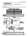
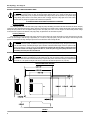
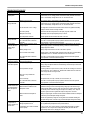
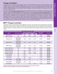
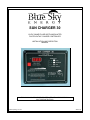
SUN CHARGER 30
12VDC 30AMP PULSE WIDTH MODULATED
PHOTOVOLTAIC CHARGE CONTROLLER
INSTALLATION AND OPERATION
MANUAL
THIS MANUAL INCLUDES IMPORTANT SAFETY INSTRUCTIONS FOR MODEL SC30
SAVE THESE INSTRUCTIONS.
© Blue Sky Energy, Inc. 2012
430-0031 B
Blue Sky Energy – Sun Charger 30
TABLE OF CONTENTS
IMPORTANT SAFETY INSTRUCTIONS ................................................................................................................................ 2
PRODUCT DESCRIPTION...................................................................................................................................................... 3
Part Numbers and Options ..................................................................................................................................... 3
OPERATION ......................................................................................................................................................................... 3
Charge Status Indication ........................................................................................................................................ 3
Digital Display ......................................................................................................................................................... 3
Solar Charge Amp-Hour Counter ........................................................................................................................... 3
Battery Level Graphic ............................................................................................................................................. 4
3-Stage Charge Control ......................................................................................................................................... 4
Bulk Charge ................................................................................................................................... 4
Absorption Charge ......................................................................................................................... 4
Float Charge .................................................................................................................................. ..4
Two Stage Charge Control ..................................................................................................................................... 5
Optional Temperature Compensation .................................................................................................................... 5
Equalization ............................................................................................................................................................ 5
30 Amp Current Limit ............................................................................................................................................. 6
Maximum Setpoint Voltage Limit ............................................................................................................................ 5
Pulse Width Modulation .......................................................................................................................................... 6
Panel Temperature and Thermal Protection .......................................................................................................... 6
Multiple Charge Controllers On The IPN Network.................................................................................................. 5
INSTALLATION....................................................................................................................................................................... 6
Selecting PV Modules ............................................................................................................................................ 6
Electrostatic Handling Precautions......................................................................................................................... 6
Charge Parameter Settings .................................................................................................................................... 7
As Shipped Factory Default Settings ............................................................................................. 7
Changing Charge Parameter Settings ........................................................................................... 7
Restoring As Shipped Factory Default Settings ............................................................................. 8
Battery and PV Wiring ............................................................................................................................................ 8
Optional Battery Temperature Sensor.................................................................................................................... ..8
Battery & PV Power Connect/Disconnect Order .................................................................................................... 9
Mounting ................................................................................................................................................................. 9
TROUBLESHOOTING GUIDE ................................................................................................................................................ 10
SPECIFICATIONS ................................................................................................................................................................... 11
FIVE YEAR LIMITED WARRANTY......................................................................................................................................... 11
TABLES AND FIGURES
Table 1
Table 2
Table 3
Figure 1
Figure 2
Figure 3
Figure 4
1
Charge Status ................................................................................................................................ 3
Charge Parameter Settings............................................................................................................ ..7
Maximum Conductor Pair Length – 3% Voltage Drop ................................................................... ..8
Front Panel Operation & Indicators ................................................................................................ 4
Factory Charge Voltage Setpoints -vs.- Battery Temperature ....................................................... 5
Wiring Diagram .............................................................................................................................. 8
Detailed Dimensional Drawing ....................................................................................................... 9
Installation and Operation Manual
IMPORTANT SAFETY INSTRUCTIONS
This manual contains important instructions for Model SC30
SAVE THESE INSTRUCTIONS
1. Refer installation and servicing to qualified service personnel. Incorrect installation or use may result in risk of electric shock or fire. No user serviceable parts
in this unit.
2. To reduce the risk of electric shock, fire or personal injury, the following symbols are placed throughout this manual to indicate dangerous conditions, or
important safety or operational instructions.
WARNING
CAUTION
IMPORTANT
)
Indicates dangerous conditions or electric
shock potential. Use extreme caution.
Indicates items critical to safe installation or
operation of the unit.
Follow these instructions closely for proper
operation of the unit
3. PERSONAL PRECAUTIONS
a) Working in the vicinity of lead-acid batteries is dangerous. Batteries produce explosive gasses during normal operation.
b) To reduce risk of battery explosion, follow these instructions and those published by battery manufacturer and manufacturer of any equipment you intend
to use in vicinity of battery.
c) Someone should be within range of your voice or close enough to come to your aid when you work near a lead-acid battery.
d) Have plenty of fresh water and soap nearby in case battery acid contacts skin, clothing or eyes.
e) Wear complete eye protection and clothing protection. Avoid touching eyes while working near battery.
f) If battery acid contacts skin or clothing, wash immediately with soap and water. If acid enters eye, immediately flood eye with running cold water for at
least 15 minutes and get medical attention immediately.
g) NEVER SMOKE or allow a spark or flame in vicinity of battery.
h) Be extra cautious to reduce risk of dropping metal tool onto battery. It might spark or short circuit battery or other electrical part that may cause explosion.
i) Remove personal metal items such as rings, bracelets and watches when working with a lead-acid battery. A lead-acid battery can produce a short circuit
current high enough to weld a ring or the like to metal, causing a severe burn.
j) Remove all sources of power, photovoltaic and battery before servicing or installing.
4. CHARGER LOCATION & INSTALLATION
a) This unit is designed to charge 12 volt (6 cell) flooded or sealed type lead-acid chemistry batteries within the range of 20 to 2,000 amp-hours. Follow
battery manufacturers charging recommendations when considering this unit for use with other battery chemistry.
b) This unit employs components that tend to produce arcs or sparks. NEVER install in battery compartment or in the presence of explosive gases.
c) This unit must be installed and wired in accordance with National Electrical Code, ANSI/NFPA 70.
d) Over current protection for the battery must be provided externally. To reduce the risk of fire, connect to a circuit provided with 40 amperes maximum
branch-circuit over current protection in accordance with National Electrical Code, ANSI/NFPA 70.
e) Insure that charge parameters are properly configured for the battery being charged as recommended by the battery manufacturer.
f)
This unit is not water tight. Do not expose to rain, snow or excessive moisture.
g) Insure all terminating connections are clean and tight. Tighten Battery and PV compression terminals to 4.4 in-lb (0.5 nm) and battery temperature sensor
compression terminals to 2.1 in-lb (0.24 nm).
h) Do not connect to a PV array capable of producing greater than 27 amps of short circuit current ISC, or 24 volts open circuit voltage VOC @ STC.
5. PREPARING TO CHARGE
a) Never charge a frozen battery.
b) Be sure battery is mounted in a well ventilated compartment.
c) Add distilled water in each cell of a lead-acid battery until battery acid reaches level specified by battery manufacturer.
2
Blue Sky Energy – Sun Charger 30
PRODUCT DESCRIPTION
The Sun Charger 30 is a 30 amp 12 volt Pulse Width Modulated (PWM) photovoltaic (PV) battery charge controller. The SC30’s sophisticated 3-stage
plus equalization charge control system improves battery performance and life while minimizing battery maintenance. The unit is electronically protected
against voltage transients, over temperature, over current, short circuit, swapped battery & PV, and reverse battery & PV polarity. A current limit feature
minimizes the likelihood of overload by limiting average output current to 30 amps maximum during periods of unusually high PV power production.
A very low power LED display is provided to monitor battery voltage and PV charge current. The display system also includes a resettable amp-hour counter
which computes total PV amp-hours produced.
PART NUMBERS AND OPTIONS
• SC30 ................... Sun Charger 30 solar charge controller
• SC30-LVD ........... SC30 with Load & Lighting control drive signal
(-LVD version by special order only, contact factory)
• 930-0022-20 ..................... Optional battery temperature sensor
• 720-0011-01 ..................... Optional wall mounting box, black powder coated
OPERATION
Basic charge control operations are fully automatic and require no operator intervention. When sufficient PV power is available the SC30 will switch to
a Charge ON state and begin charging the battery. The particular charge mode the SC30 will operate in will vary depending on the needs of the battery and
12 volt electrical system, and available PV charge current. When insufficient PV current is available to charge the battery the SC30 will switch to a Charge
Off state. At night when the SC30 is in a Charge Off state the PV array is disconnected from the battery to prevent unwanted current drain. There is a 5
second turn-on delay, and a 30 second turn-off delay.
)
¾ The SC30 operates on battery power, not PV power. Insure that voltage on the battery terminals of the SC30 is always the
same as actual battery voltage within a few 10ths of a volt for proper operation. A battery must be connected with a minimum
voltage of 9 volts for the unit to operate. Note that the front panel serves as a heatsink for power control devices and may
become quite warm during normal operation.
¾ CAUTION: Do not disconnect the battery while the SC30 is in a Charge ON state. A healthy battery is a key component of PWM
charge voltage control and provides charge voltage filtering. Sudden removal of the battery while the SC30 is charging will produce
voltage spikes at the SC30’s battery terminals which may damage 12 volt appliances still connected to the SC30.
IF THE BATTERY MUST BE DISCONNECTED, REMOVE PV POWER FIRST.
CHARGE STATUS INDICATION
Present charge status of the SC30 is indicated using two charge status LED’s, Absorption & Float. If net battery charge current is greater than about 3 to 5
amps per 100 amp-hours of battery capacity the charge status indicator can provide a rough indication of battery state of charge.
CHARGE STATUS
CHARGE STATUS LED’s
ABSORPTION & FLOAT OFF
ABSORPTION & FLOAT ON
ABSORPTION ON – FLOAT OFF
ABSORPTION OFF – FLOAT ON
ABSORPTION & FLOAT
ALTERNATELY BLINKING
CHARGE MODE
CHARGE OFF
BULK
ABSORPTION
FLOAT
APPROXIMATE CHARGE LEVEL
<70% FULL
70% - 95% FULL
FULLY CHARGED
EQUALIZE
TABLE 1
DIGITAL DISPLAY
When the SC30 first boots and completes self-test, the VOLT/AMP display mode is active. This mode displays Battery Voltage continuously if the
SC30 is in a Charge Off state, or alternates between Battery Voltage & Output Charge Current if the SC30 is in a Charge On state. The AMPS indicator in the
upper left of the display will be on whenever current is displayed. To provide good readability during the day yet minimize the likelihood of the display being
objectionably bright at night an automatic night time dimming feature is provided which dims the display when the SC30 is in a Charge Off state.
Other display modes may be selected using the Display Select push-button. Each brief press of Display Select selects the next display mode as shown on
the front panel graphic of Figure 1. VOLT shows Battery Voltage, AMP shows Output Charge Current, and AMP-HRS shows total PV Amp-Hours produced since
the amp-hour counter was last cleared. One more brief press after AMP-HRS turns the display off completely. Each brief press of Display Select moves to the next
display mode in a continuous loop as shown on the front panel graphic. Note that the Amp-Hours are shown in whole numbers without a decimal point.
SOLAR CHARGE AMP-HOUR COUNTER
The battery essentially serves as a “storage tank”, with the battery storing electrical energy in units referred to as amp-hours. Amp-hours are
computed by multiplying current in amps X time in hours. For example 20 amp-hours may be a current of 10 amps flowing for 2 hours, or may be 1 amp
flowing for 20 hours. The battery receives and stores amp-hours when being charged, and then delivers those stored amp-hours when being discharged. As
a broad approximation typical lead-acid batteries including GEL and AGM are about 95% efficient in absorbing charge amp-hours.
3
Installation and Operation Manual
The amp-hour counter displays total solar charge amp-hours accumulated since the last time the counter was cleared up to a maximum count of 999
amp-hours. Amp-hour production varies widely with operating conditions, but as a very broad brush approximation 100 watts of PV modules can deliver up to
a maximum of about 30 amp-hours per day. Any partial shading, lower sun intensity, shorter days, or time spent in Absorption or Float will decrease amphours produced. The present amp-hour count may be cleared by pressing Display Select for 5 seconds while viewing amp-hours on the display.
BATTERY LEVEL GRAPHIC
The SC30 provides a battery level graphic on the front panel which indicates approximate battery level versus battery voltage. Generally a higher voltage is
better than a lower voltage. Note that the graphic does not illuminate.
A battery that is being charged will typically range in voltage from about 12.5 volts after charge commences, to perhaps 14.0 volts or greater when the
battery is highly charged. Once charge stops and the battery begins discharging and delivering power to a load it is normal for battery voltage to drop. A battery
under a light load of about 1 amp per 100 amp-hours of battery capacity may range between about 12.5 volts when the battery is full, down to perhaps 12.0 volts
when the battery is about 50% discharged. Battery voltage during discharge will tend to be higher under light load and lower under a heavier load.
Do not think of these voltage values as absolutes but rather as a broad brush indication of battery level. Voltage at a particular state of charge will vary with
battery size, age, construction, temperature, and with the level of charge or discharge current. Most battery manufacturers recommend not discharging below
about 50% DOD (depth of discharge) to promote improved battery performance and life. Avoid allowing battery voltage to drop below about 11.5 volts, and NEVER
allow battery voltage to drop below 10.0 volts.
Digital Display
May show battery voltage,
solar charge current, or solar
charge amp-hours. AMP
indicator be on if showing
solar charge current. Display
automatically dims at night.
FRONT PANEL OPERATION & INDICATORS
Charge Status LED’s
Shows present charge mode.
Setup Push-Button
Used with Display Select to
view or change charge
parameter settings.
Display Select push-button
Selects display mode. May
also be used to clear solar
charge amp-hours or
start/stop Equalize.
Front Panel heating
Panel serves as a heatsink
for power control devices,
may become quite warm
during normal operation.
Battery Level Graphic
Shows approximate battery
level vs. battery voltage.
FIGURE 1
3-STAGE CHARGE CONTROL
The SC30 is factory configured for a 3-stage charging process, Bulk, Absorption and Float, which is fully automatic and requires no operator
intervention. The 3-stage charge process applies a somewhat higher Absorption charge voltage to charge the battery quickly and safely. Once the battery is
fully charged a somewhat lower Float voltage is applied to maintain the battery in a fully charged state without excessive water loss.
)
¾ The charge control system always starts in Absorption and will return to Absorption upon exiting Current Limit or Equalization.
Following a 20 second delay in Absorption the SC30 may move on to other charge modes based on battery and system needs.
Bulk Charge
The SC30 will switch to Bulk charge when battery voltage remains below the present charge voltage setpoint. During Bulk the SC30 delivers as much
charge current as possible to rapidly recharge the battery. During Bulk it is a combination of battery size, state of charge and available charge current that
determine battery voltage, not the SC30.
Absorption Charge
When the battery recovers sufficient charge for battery voltage to rise to the Absorption Charge Voltage setpoint (factory set to 14.4V), charge current is
reduced as necessary to hold the battery at the Absorption Voltage. The SC30 remains in Absorption until the battery is fully charged as determined by the
SC30 remaining continuously in Absorption for the Absorption Charge Time period (factory set to 2 hours). The SC30 will return to Bulk should battery
voltage remain below the Absorption Voltage setpoint for more than 20 seconds.
Float Charge
Once the battery is fully charged a somewhat lower Float Voltage (factory set to 13.2V) is applied to maintain the battery in a fully charged state
without excessive water loss. The SC30 will return to Absorption should battery voltage remain below the Float Voltage setpoint for more than 20 seconds.
4
Blue Sky Energy – Sun Charger 30
2-STAGE CHARGE CONTROL
Certain battery types or system configurations may require 2-stage Bulk/Absorption charge control. The SC30 can be configured for 2-stage charge control
by setting the Float Charge Voltage to OFF.
OPTIONAL TEMPERATURE COMPENSATION
The charge voltage required by batteries changes with battery temperature. Temperature compensation of charge voltage enhances battery
performance and life while decreasing battery maintenance. Temperature compensation of charge voltage can be provided using the optional battery
temperature sensor (BSE p/n 930-0022-20). The default compensation factor of –30mV/°C is typically appropriate for most lead-acid chemistry batteries
including GEL and AGM. If a proper temperature sensor signal is not detected the SC30 will operate as if battery temperature is 25°C.
FACTORY DEFAULT CHARGE VOLTAGE SETPOINTS -VS.- BATTERY TEMPERATURE
FIGURE 2
EQUALIZATION
¾ WARNING: Not all batteries can be safely equalized. Equalization should be performed only on vented liquid electrolyte
lead-acid batteries. Always follow battery manufacturers recommendations pertaining to equalization. Equalization applies a
relatively high charge voltage producing significant battery gassing. Prior to performing equalization disconnect equipment that
cannot tolerate the high equalization voltage which is temperature compensated as shown above.
Equalization is essentially a controlled overcharge which applies a relatively high charge voltage to bring all battery cells up to the same specific gravity and
state of charge. The SC30 may be configured to perform either an automatic equalization on periodic basis, or a manually initiated equalization. Since sealed
batteries should not be equalized the factory default settings have Equalize Enable set to OFF to completely disable automatic or manual equalization. Equalization
may be enabled by setting Equalize Enable to ON as described in the Charge Parameter Settings section. When an equalization cycle is being performed the Float
and Absorption charge status LED’s will alternately blink.
With equalize enabled the SC30 will perform an automatic equalization at the factory default settings of 15.2V for 2 hours every 30 days which is typically
suitable for most flooded lead-acid batteries. When set for automatic equalization the cycle will begin when the set number of days since the last equalization has
elapsed, and the charge control system has switched to Float. When set for manual equalization (Equalize days set to 00) an automatic equalization will not occur.
Whether set for automatic or manual the process may be started or stopped manually by pressing the Display Select push-button for 20 seconds.
Once equalization has started the equalize timer will not count down unless battery voltage is at the equalize voltage setpoint which is temperature
compensated. Therefore obtaining a proper 2 hour equalization will require longer than 2 hours to complete depending on available charge current. Note that at
least 3.5 amps of net charge current per 100 amp-hours of battery capacity is typically required to properly equalize a battery. If equalization does not complete
during the charging day it will resume where it left off the next charging day, but will automatically cancel if unable to complete within 24 hours. The equalize day
counter is reset whenever an equalization cycle is started.
30 AMP CURRENT LIMIT
Should transient conditions be present where the PV modules are able to produce more than 30 amps of output current, the SC30 will automatically
limit average output current to 30 amps. It is possible for output current to briefly exceed 30 amps as the current limit control system responds to sudden
increases in PV current. Note that when current drops and the SC30 exits current limit it will first enter Absorption (for 20 seconds) on its way back to Bulk
even though battery voltage may be below the Absorption Charge Voltage setpoint.
¾ WARNING: Current limit should be thought of as transient PV over current protection and not a normal mode of operation. If
the SC30 enters current limit and/or delivers 30 amps of output on a regular basis it is possible that excessive PV power is
connected. Confirm that the PV modules do not exceed ratings shown in the Selecting PV Modules section. If necessary
remove some PV power to keep normal operation below 30 amps.
5
Installation and Operation Manual
MAXIMUM SETPOINT VOLTAGE LIMIT
The maximum setpoint voltage limit is not a charge voltage setting but rather places a maximum limit or ceiling on the charge voltage setpoint actually
used by the SC30 in all charge modes. Regardless of setpoint values entered by the user or how setpoints may adjust due to temperature compensation the
SC30 will not use a charge voltage setpoint greater than the maximum setpoint voltage limit factory set to 15.5V. The purpose of the maximum setpoint voltage
limit is to prevent charge voltage from getting so high that Inverters or other equipment shut down due to excess voltage. Note that actual battery voltage
may briefly exceed this value by perhaps 0.1 – 0.2V as the voltage control system responds to sudden changes in loads or available PV current.
PULSE WIDTH MODULATION
The SC30 uses Pulse Width Modulation (PWM) charge voltage control. When battery voltage is below the present charge voltage setpoint the PV module is
continuously connected to the battery to deliver maximum charge current. Once the battery recovers sufficient charge for voltage to rise to the charge voltage
setpoint, charge current must be reduced to regulate battery voltage or voltage would continue to climb. When a reduction in charge current is necessary the PWM
control system reduces average current delivery by rapidly connecting and disconnecting the PV module at a fixed frequency of 50Hz. The rapid on/off switching of
PV charge current may produce a slight 50Hz buzzing sound which may come from the SC30 or user installed wiring.
If only 80% of the available PV current is required to hold battery voltage at setpoint the PV is connected (or turned on) for 80% of the time and remains off
for 20% of the time. The control system varies or “modulates” the ON time “pulse width” percentage as necessary to control battery voltage, hence the term Pulse
Width Modulation. Because charge current is either full on or full off during PWM control the battery provides a very important voltage filtering function in a PWM
control system due to its very stiff resistance to changing voltage quickly. Therefore a battery must always be connected to provide proper voltage control.
PANEL TEMPERATURE AND THERMAL PROTECTION
Internal power control devices use the front panel as a heatsink. It is normal for the front panel to become quite warm to the touch when the SC30 is
operating at high power. When mounted to a vertical surface with good ventilation, the SC30 can deliver full output in an ambient temperature of up to 45°C
(113°F). If an over temperature condition exists, the SC30 will simply cycle on and off to keep internal temperature within acceptable limits.
INSTALLATION
¾ WARNING: The SC30 is designed for use with 12 volt DC electrical systems only. Read, understand and follow the Important
Safety Instructions in the beginning of this manual before proceeding. This unit must be installed and wired in accordance with
National Electrical Code, ANSI/NFPA 70. Over current protection must be provided externally. To reduce the risk of fire, connect to
a circuit provided with 40 amp maximum branch-circuit over current protection in accordance with National Electrical Code,
ANSI/NFPA 70. Do not connect a PV array capable of delivering greater than 27 amps short circuit current (ISC) or 24 volts open
circuit voltage (VOC) at STC. Do not connect BAT– & PV– together external to the unit. To reduce risk of electric shock or product
damage, remove all power before installing or servicing. Figure 3 shows generalized connections only is not intended to show all
wiring, circuit protection and safety requirements for a photovoltaic electrical system.
¾ CAUTION: The SC30 is protected against reverse battery polarity, short duration reverse PV polarity, and swapped PV and
battery connections. The SC30 will be damaged by long duration reverse PV, reverse battery to the PV terminals, and voltage in
excess of 30 volts on the battery or PV terminals.. Damage resulting from these user induced faults voids the limited warranty.
SELECTING PV MODULES
The SC30 is designed to work with 12V PV modules only. Higher voltage modules or input power sources other than PV modules will damage the SC30 in
a manner which voids the limited warranty. Voltage, current and power produced by PV modules vary widely with operating conditions. As a result a set of test
conditions referred to as Standard Test Conditions or STC are used to rate modules in a meaningful manner and the manufacturer’s published STC ratings
that must be used when selecting PV modules. STC ratings are not maximum or optimal ratings. Operating conditions can be present where PV voltage and
current may exceed published STC ratings which is why PV module voltage and current must be limited to the values shown below. While conditions may be
present where VOC, ISC & IMP exceed STC ratings, in real world conditions actual charge current typically seen may only be about 75 – 80% of IMP at STC.
Key PV module specifications;
PMAX Maximum power in watts (PMAX = VMP x IMP)
VOC
Voltage with module open circuit (typically ≈20 – 23V for 12V nominal modules)
VMP
Voltage where module produces Maximum Power (typically ≈17 – 18V for 12V nominal modules)
Current where module produces Maximum Power
IMP
Current with module Short Circuit
ISC
Select PV modules that DO NOT exceed the maximum ratings below and preferably deliver at least 3 amps IMP per 100 amp-hours of battery capacity.
Maximum PV Power @
STC
450W
Maximum PV
Isc @ STC
27.0A
Maximum PV
VOC @ STC
24.0V
Recommended range of VMP at STC
Nominal 12V PV
16.0 – 19.0V
ELECTROSTATIC HANDLING PRECAUTIONS
All electronic circuits may be damaged by static electricity. To minimize the likelihood of electrostatic damage, discharge yourself by touching a water faucet
or other electrical ground prior to handling the SC30. The risk of electrostatic damage is highest when relative humidity is below 40%.
6
Blue Sky Energy – Sun Charger 30
CHARGE PARAMETER SETTINGS
The SC30 contains various charge parameter settings all of which are preconfigured at the factory to the default settings shown below. Most
installations require no changes to these settings which are typically suitable for most flooded, GEL and AGM lead-acid chemistry batteries.
¾ WARNING: If charge parameter settings are changed, confirm that the new settings comply with the battery manufacturers
recommendations. DO NOT enable equalization for sealed lead-acid batteries such as GEL and AGM.
As Shipped Factory Default Settings
•
•
•
•
•
Charge mode ..............................................
Absorption voltage .....................................
Absorption time ..........................................
Float voltage ................................................
Maximum setpoint voltage limit ..................
•
•
•
•
•
3-stage
14.4V
2.0 hours
13.2V
15.5V
Equalize enable ........................................................
Equalize time ............................................................
Equalize voltage .......................................................
Auto equalize days ...................................................
Temperature compensation factor ...........................
Off (disabled)
2.0 hours
15.2V
30 days
−30mV/°C
Changing Charge Parameter Settings
SC30 charge parameter settings may be viewed or changed at any time using a combination of the Setup and Display Select push-buttons. There are
two modes of setup operation, Viewing a setting and Changing a setting. Basic operation is to go from Normal Operation to Viewing Mode, Viewing Mode to
Changing Mode, and then from Changing mode back to Viewing mode, and Viewing Mode back to Normal Operation. All settings are stored in Flash memory
and are retained if power is lost.
Normal Display Operation
Viewing a setting
To enter the Viewing Mode press Setup 5 seconds and release when AbS appears in the display. The first
parameter to be shown is the Absorption Charge Voltage setting. The display will alternate between AbS and 14.4
to show the present Absorption Charge Voltage setting is 14.4V.
A brief press of Setup within 5 seconds will move to the next setting shown in Table 2, Absorption Charge Time
where the display will now alternate between Abt and 2.0 to show the present Absorption Charge Time setting is
2.0 hours. Remaining settings may be viewed by repeatedly pressing Setup to move to the desired setting. To exit
Viewing Mode and return to normal operation, do not press Setup for 5 seconds.
Parameter Viewing mode
Parameter Changing Mode
Changing a setting
To enter the Changing Mode, first enter the Viewing Mode for the setting to be changed. While in Viewing Mode for
that setting, press Setup 5 seconds to enter the Changing Mode for that setting. The present setting value will begin
blink rapidly indicating that you have entered the parameter changing mode for that setting. Use Display Select to
scroll through the available values until the desired value is reached. With the desired new value blinking in the
display press Setup 5 seconds to save the new setting. Once the new setting is saved the display will revert back
to the Viewing Mode showing the new saved value for that setting.
If neither Setup or Display Select is pressed within 5 seconds while in the Changing Mode, the change request is
abandoned and the display reverts back to Viewing Mode without changing the setting.
CHARGE PARAMETER SETTINGS
Parameter viewing mode toggles
between setting text and the present
value of that setting
Setting Text
Default Setting
AbS
14.4
Abt
2.0
FLt
13.2
Setting Range
Setting Steps
Description
12.0V – 17.0V
0.0 – 10.0 hrs
12.0V – 17.0V
0.1V
0.5 hrs
0.1V
Absorption charge voltage
Absorption charge time
Float charge voltage
Set to oFF (one step below 12.0) for 2-stage charge
Equalize charge voltage
Equalize charge time
Auto equalize days. Setting of zero (00) selects manual equalization.
Master equalize enable/disable
Set to on to enable equalization
Maximum setpoint voltage limit
Battery temperature compensation factor
(decimal point missing in display such that 500 = –5.00mV/°C/cell
Default provides overall factor of –30mV/°C for 6 cell 12V battery)
EqU
Eqt
Eqd
EqE
15.2
2.0
30
oFF
12.0V – 17.0V
0.5 – 10.0 hrs
10 – 400
on or oFF
0.1V
0.5 hrs
5 days
uPr
btc
15.5
500
(–5.00mV/°C/cell)
12.0V – 17.0V
000 – 800
(–0.00 to –8.00
mV/°C/cell)
0.1V
10
(0.10mV/°C/cell)
TABLE 2
7
Installation and Operation Manual
Restoring As Shipped Factory Default Settings
1. Remove both PV and battery power.
2. Apply battery power while pressing & holding the Setup push-button.
3. Following display self-test, confirm display shows software revision
(e.g., r1.4) & Charge Status LED’s remain on while Setup is held.
4. After at least 5 seconds, release Setup.
5. Confirm display resumes normal operation.
6. The SC30 is now set to as shipped factory defaults.
BATTERY AND PV WIRING
A desirable installation will produce a total system wiring voltage drop of 3% or less. The lengths shown in Table 3 are one way from the PV modules to the
battery with the SC30 located along the path. Wire length can be increased inversely proportional to actual current. If current was reduced by 1/2 wire lengths could
be doubled and still provide the same 3% voltage drop.
MAXIMUM CONDUCTOR PAIR LENGTH – 3% VOLTAGE DROP
WIRE GAUGE
AWG
12 AWG
10 AWG
8 AWG
6 AWG
4 AWG
2 AWG
12 VOLT SYSTEM @27A
FEET / METERS
4.8 / 1.5
7.6 / 2.3
12.0 / 3.7
19.2 / 5.9
30.3 / 9.2
48.3 / 14.7
TABLE 3
¾ CAUTION: Battery and PV compression terminals will accept #16 − #8 AWG wire and are to be tightened to 4.4 in-lb (0.50
nm). Temperature Sensor compression terminals accept #26−14 AWG wire and are to be tightened to 2.1 in-lb (0.24 nm). Take
care to route and strain relief wires in a manner that does not place undue strain on the SC30’s compression terminal blocks.
WIRING DIAGRAM
FIGURE 3
OPTIONAL BATTERY TEMPERATURE SENSOR
Install the optional battery temperature sensor as shown in Figure 3. The temperature sensor will be automatically detected by the SC30.
¾ WARNING: Use only BSE temperature sensor p/n 930-0022-20. Other temperature sensors or electrical connections to the
temperature sensor terminals may damage the SC30, void the limited warranty, and may cause charge voltage to become
uncontrolled. Note that temperature sensor wires are polarized RED/BLK and the sensor will not function if installed reverse
polarity. The temperature sensor lug may connect to any battery terminal.
8
Blue Sky Energy – Sun Charger 30
BATTERY & PV POWER CONNECT/DISCONNECT ORDER
¾ CAUTION: When applying power to the SC30, battery power should be connected first followed by PV power. Disconnect PV
power first when removing power. DO NOT disconnect the battery while the SC30 is in a Charge ON state with PV power
connected. A healthy battery is a key component of the PWM charge voltage control system and provides a very important charge
voltage filtering function. Removal of the battery while the SC30 is charging will produce voltage spikes at the SC30’s battery
terminals which may damage 12V appliances still connected to the output SC30.
IF THE BATTERY MUST BE DISCONNECTED, REMOVE PV POWER FIRST.
Connecting the Battery
Before attaching battery wires to the SC30 confirm proper voltage and polarity. With battery power attached the SC30 should boot and self-test. All display
segments and LED’s will briefly illuminate during self-test, followed by a brief display of the software revision. Following self-test battery voltage will be displayed
although the display will be dim due to the night time dimming function. If the display does not turn on check voltage on the SC30’s battery terminals. Voltage
should be the same as present on the batteries, of the proper polarity, and greater than 9 volts for the SC30 to operate.
Connecting PV Modules
Before attaching PV wires to the SC30 confirm proper voltage and polarity. Measure PV module voltage with PV modules disconnected from the SC30.
Confirm open circuit voltage is within the range of approximately 18 – 22 volts, and of the proper polarity. If PV open circuit voltage is outside this range confirm
proper PV module selection and wiring. Attaching PV power should cause the SC30 to switch to Charge ON state.
¾ CAUTION: PV voltage exceeding 30 volts will damage the SC30 and void the limited warranty. The SC30 is protected against
limited duration reverse PV polarity. If available PV current is high and reverse PV polarity duration is long, damage may result which
voids the limited warranty. Immediately following PV power connection confirm that the SC30 display continues to operate normally
and the unit switches to a Charge On state as expected. Reverse PV connection will cause the display to continuously show
the self-test indication of all display segments and LED’s on, and the front panel may get hot quickly. Should this occur
immediately remove PV power and correct the fault.
MOUNTING
¾ CAUTION: Mount the SC30 vertically to promote air flow and cooling, do not enclose in a confined space and avoid mounting in
direct sunlight. The SC30 is not watertight and must be protected from rain, snow and excessive moisture. Corrosion resulting from
liquid water or excessive moisture voids the limited warranty. An optional black powder coated deluxe mounting box available as BSE
p/n 720-0011-01. The optional mounting box is the same X,Y dimension as the SC30 front panel and 2.75” (7cm) deep.
DETAILED DIMENSIONAL DRAWING
FIGURE 4
9
Installation and Operation Manual
TROUBLESHOOTING GUIDE
SYMPTOM
PROBABLE CAUSE
ITEMS TO EXAMINE OR CORRECT
Completely dead,
display blank.
No battery power.
Battery disconnected, overly discharged, or connected reverse polarity. Battery
powers SC30, not PV. Voltage present on the SC30’s battery terminals must be the
same as actual battery voltage within a few 10ths and at least 9 volts.
Display mode set to OFF.
No battery power.
Press Display Select to select display mode other than OFF.
Battery disconnected, overly discharged, or connected reverse polarity. Battery
powers SC30, not PV. Voltage present on the SC30’s battery terminals must be the
same as actual battery voltage within a few 10ths and at least 9 volts.
PV disconnected or low in voltage.
PV voltage when connected to the SC30 must be at least 0.3V greater than battery
voltage for SC30 to switch to Charge On State.
PV reverse polarity.
Reverse PV will heat front panel & force all display segments & LED’s ON.
Microprocessor lockup.
Momentarily remove all power (battery & PV) to re-boot.
Over temperature shutdown.
Low and changing sun intensity.
Normal operation will resume when the SC30 cools down.
Normal operation.
PV- connected to BAT- external to
controller.
Battery voltage greater than charge
voltage setpoint.
PV- & BAT- must be separate for proper operation. External connection prevents
proper operation of current measurement system.
Normal operation. Output is off due to high battery voltage which may be caused by
other charging systems, or immediately following a switch to Float before battery
voltage dropped and settled.
Battery voltage too low.
Battery voltage must be at least 9 volts for the SC30 to operate.
Poor connection to the battery.
Voltage present on the SC30’s battery terminals must be the same as actual battery
voltage within a few 10ths. Examine connections and fuse & fuse holder.
PV- connected to BAT- external to
controller.
System temporarily shuts down due to
high internal temperature.
Battery is highly charged.
PV- & BAT- must be separate for proper operation. External connection prevents
proper operation of current measurement system.
Improve ventilation or reduce PV power.
User expectations too high.
Even though the PV’s may be in full sun, clean, and with zero shading it is common to
only see about 75 – 80% of total PV IMP. Note that the smallest amount of shade can
cause a large reduction in charge current.
Worn out or very dissimilar PV
modules
Replace, or use as is.
Low sun intensity
Atmospheric haze, PV’s dirty or shaded, sun low on horizon, etc.
PV- connected to BAT- external to
controller.
Not set for 3-stage charge.
PV- & BAT- must be separate for proper operation. External connection prevents
proper operation of current measurement system.
Confirm Float voltage setpoint is not set to OFF.
Will not switch out of Bulk and into
Absorption or Float.
Available net charge current cannot bring battery voltage up to the desired charge
voltage setpoint. Battery may be too large, PV power too low, and/or loads too high.
PV’s should produce at least 3 amps per 100 amp-hours of battery –and– daily PV
amp-hours produced must be greater than daily load amp-hours consumed.
Will not switch from Absorption to
Float.
Battery not fully charged. Unit will not switch to Float until SC30 remains in Absorption
continuously for the Absorption Charge Time period.
Temperature sensor missing.
Periodic load pulls battery voltage low causing SC30 to re-enter Bulk resetting the
Absorption Charge Timer. Consider using a shorter Absorption Charge Time setting.
Install battery temperature sensor BSE p/n 930-0022-20.
Wrong temperature sensor.
Use only BSE battery temperature sensor p/n 930-0022-20.
Temperature sensor failed or installed
reverse polarity.
If sensor is open, short, reverse polarity or missing SC30 will operate as if battery
temperature is 25°C. Proper sensor voltage when excited by the SC30 will read
approximately 2.98V at 25°C, changing at +10mV/°C.
Unit will not switch to
Charge ON state.
Unit will not stay in a
Charge ON state.
Charge status
indicator ON but no
output charge
current.
Charge OFF at high
ambient temperature.
Charge current is
lower than expected.
System appears to
operate OK, but will
not switch between
Bulk, Absorption &
Float.
Temperature
compensation of
charge voltage does
do not work.
Normal operation. Current is intentionally reduced in Absorption & Float to control
battery voltage at setpoint. Maximum available charge current will only be seen when
the SC30 is in Bulk.
10
Blue Sky Energy – Sun Charger 30
SPECIFICATIONS
SPECIFICATIONS
Nominal Battery Voltage
Output Current Rating
PV Input Voltage
Power Consumption
Charge Algorithm
Absorption / Float / EQ Voltage
Display Range & Accuracy
Dimensions
Environmental
Sun Charger 30
12 volts DC
30 amp maximum (Recommend maximum ISC at STC ≤ 27 amps)
30 volts DC absolute maximum (Recommend maximum VOC at STC ≤ 24V)
14mA typical standby • 19mA typical display ON
3-stage Bulk/Absorption/Float • Plus Auto/Manual Equalization
14.4V / 13.2V / 15.2V (user adjustable)
Battery voltage 30.0VDC±0.5% • PV current 35.0A±0.5%
6.4” (16.3cm) W x 4.6” (11.7cm) H x 1.2” (3.0cm) D
-40 – +45°C, 10 – 90% RH non-condensing
FIVE YEAR LIMITED WARRANTY
Blue Sky Energy, Inc. (hereinafter BSE), hereby warrants to the original consumer purchaser, that the product or any part thereof shall be free from
defects due to defective workmanship or materials for a period of five (5) years subject to the conditions set forth below.
1.
This limited warranty is extended to the original consumer purchaser of the product, and is not extended to any other party.
2.
The limited warranty period commences on the date the product is sold to the original consumer purchaser. A copy of the original purchase receipt
identifying purchaser and date of purchase, must accompany the product to obtain warranty repairs.
3.
This limited warranty does not apply to, and future warranty shall become void, for any product or part thereof damaged by; a) alteration, disassembly
or application of a foreign substance, b) repair or service not rendered by a BSE authorized repair facility, c) accident or abuse, d) corrosion, e) lightning
or other act of God, f) operation or installation contrary to instructions pertaining to the product, or g) cosmetic aging.
4.
If BSE’s examination of the product determines that the product is not defective the consumer shall be charged a test and evaluation fee of $20 and be
responsible for all transportation costs and insurance related to returning the product to the consumer. The consumer is ultimately responsible for
proper installation and operation of the product and BSE’s prior troubleshooting assistance shall not serve as a waiver of the test and evaluation fee.
The test and evaluation fee is subject to change without prior notice.
5.
If within the coverage of this limited warranty, BSE shall repair or replace the product at BSE’s sole discretion and return the product via standard
ground transportation of BSE’s choosing within the continental US. The consumer shall be responsible for all transportation costs and insurance to
return the product outside the continental US, and for all transportation costs and insurance related to expedited return of the product. BSE’s liability for
any defective product or any part thereof shall be limited to the repair or replacement of the product. BSE shall not be liable for any loss or damage to
person or property, or any other damages, whether incidental, consequential or otherwise, caused by any defect in the product or any part thereof.
6.
Any implied warranty for merchantability or fitness for a particular purpose is limited in duration to the length of this warranty.
7.
To obtain warranty repairs, contact BSE at 760-597-1642 to obtain a Returned Goods Authorization (RGA) number. Mark the outside of the package
with the RGA number and return the product, postage prepaid and insured to the address below. The consumer is responsible for all transportation
costs and insurance related to returning the product to BSE, and for any shipping damage which may void the warranty or increase the cost of repairs.
Blue Sky Energy, Inc.
2598 Fortune Way, Suite K
Vista, CA 92081 USA
800-493-7877 • 760-597-1642 • Fax 760-597-1731 • www.blueskyenergyinc.com
11