1
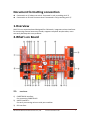
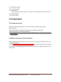
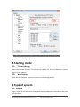
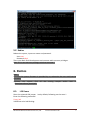
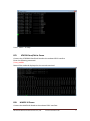
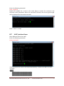
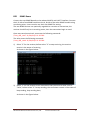
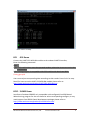
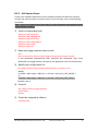
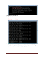
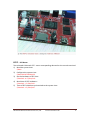
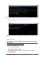
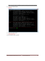
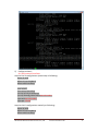
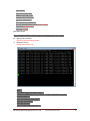
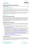
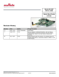
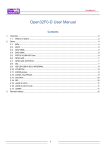
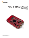
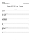
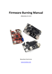
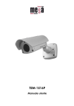
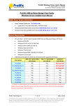
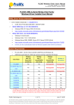
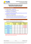
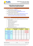
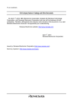
DVK570 Expansion Board User Manual 2014.04.12 V1.0 Waveshare Electronics www.wvshare.com Copyright Statement The ownership of this user manual is Shenzhen Waveshare Electronics Co., Ltd. Any manner or form of modifying, distributing or copying any parts of this document without permission is forbidden, otherwise offender will have to suffer all the consequences. Version update records Version Date Description V1.0 2014.04.12 Initial Release Shenzhen Waveshare Electronics Co., Ltd. www.waveshare.com I Contents Copyright Statement ..................................................................................................................I Version update records ..............................................................................................................I 1.Overview ............................................................................................................................... 1 2.What’s on Board .................................................................................................................... 1 2.1. Interfaces ........................................................................................................................... 1 2.2. Component ........................................................................................................................ 2 2.3. Jumper .............................................................................................................................. 2 3.Preparation .................................................................................................................................... 3 3.1 Firmware burning .............................................................................................................. 3 3.2 USB to serial port driver installation ................................................................................. 3 4.Starting mode ................................................................................................................................ 4 4.1. TF Card starting .................................................................................................................. 4 4.2. Nand starting...................................................................................................................... 4 5.Type of system ............................................................................................................................... 4 5.1 Lubuntu ............................................................................................................................. 4 5.2 Debian ............................................................................................................................... 5 6. Demos ........................................................................................................................................... 5 6.1. LED Demo ........................................................................................................................... 5 6.2. Buzzer Demo ...................................................................................................................... 6 6.3. DS18B20 Demo .................................................................................................................. 7 6.4. AD Keypad Demo ............................................................................................................... 7 6.5. AT45DB Read/Write Demo ................................................................................................. 8 6.6. MAG3110 Demo................................................................................................................. 8 6.7. UART Interface Demo ......................................................................................................... 9 6.8. RS485 Demo ..................................................................................................................... 10 6.9. GPS Demo ........................................................................................................................ 11 6.10. ZIGBEE Demo ................................................................................................................. 11 6.11. USB Camera Demo ......................................................................................................... 12 6.12. RTC Demo ....................................................................................................................... 14 6.13. WIFI Demo ..................................................................................................................... 15 Shenzhen Waveshare Electronics Co., Ltd. www.waveshare.com II Document formatting convention Commands on PC ubuntu terminal: formatted in red, preceding with '#' Commands on SD card linaro terminal: formatted in red, preceding with '$' 1.Overview DVK570 is an expansion board designed for Cubietruck, integrates various interfaces for connecting external accessory boards, supports complete sample codes, users can easily develop their own products. 2.What’s on Board 2.1. Interfaces 1) CUBIETRUCK interface: For connecting CUBIETRUCK 2) UART0 interface : For easily connecting various serial port modules 3) I2C interface: Shenzhen Waveshare Electronics Co., Ltd. www.waveshare.com 1 4) 5) 6) 7) 8) 9) 10) 11) 12) easily connects to I2C modules such as PCF8563 RTC Module, MAG3110 Board Module, etc TVIN interface: For video input TVOUT interface: For video CVBS output, can connect to devices such as TV, etc LINEIN interface: For audio input USB interface: USB TO UART(PL2303TA) UART interface: Easily connects to various modules with UART peripherals, such as RS485 Board (3.3V)、GPS modules, etc SPI interface: Easily connects to all kinds of modules with SPI peripherals, such as AT45DBXX Dataflash modules, etc ZIGBEE interface: For easily connecting to core board Core2530, used with ZB500. ONEWIRE interface: Easily connects to ONE-WIRE devices (TO-92 package), such as temperature sensor (DS18B20), electronic registration number (DS2401), etc. 5V/3.3 V power input/output: Usually used as power output, also common-grounding with other user board 2.2. Component 13) PL2303TA USB TO UART MCU 14) 12M crystal oscillator PL2303TA crystal oscillator 15) Buzzer 16) User LED 4 different color user LEDs 17) Power LED 18) AD Keypad 7 ANDROID common keypads: VOL+、VOL-、MENU、SEARCH、HOME、ESC、ENTER 2.3. Jumper 19) ONEWIRE jumper 20) Buzzer jumper Shenzhen Waveshare Electronics Co., Ltd. www.waveshare.com 2 21) AD keypad jumper 22) User LED jumper 23) TVIN jumper Users can choose video input of 4 channels, factory default is the forth channel. 24) TVOUT jumper 25) UART0 jumper 3.Preparation 3.1 Firmware burning Burning corresponding firmware: ct-dvk-xxxx.img is needed when testing DVK570 ,Click: http://dl.cubieboard.org/parteners/waveshare/Image/ to download, details please refer to “Burning Firmware”. Note:Firmware with “sdcard”marking is TF card firmware;with “nand” marking is nand firmware. 3.2 USB to serial port driver installation Connect DVK570 to Cubietruck, then connect it to PC using a mini USB wire via USB TO UART connector. Launch PL2303_Prolific_DriverInstaller_v1.8.0.exe to install the driver. After installed, launch the serial debugging assistant and check putty.exe, configure like below, then click “open”. Shenzhen Waveshare Electronics Co., Ltd. www.waveshare.com 3 Note: Check your computer’s “Device Manager”to see what the COM is. 4.Starting mode 4.1. TF Card starting Insert the burned firmware TF card to the CARD0 slot of the Cubietruck, connect electricity for starting. 4.2. Nand starting After burned firmware, connect to electricity for starting directly. 5.Type of system 5.1 Lubuntu Input "enter" at the terminal to enter Bash Shell development environment with root user privileges. Shenzhen Waveshare Electronics Co., Ltd. www.waveshare.com 4 5.2 Debian Reboot the system, input user name and password: User:root Password:chird Then enter Bash Shell development environment with root user privileges. Note: If it is not root user privilege, switch to root user! 6. Demos Note: 1.Ensure the system firmware is provided by us, otherwise the test could not be operated! 2.Reboot the system, find all the testing sample under root of /home/waveshare_demo/API. 6.1. LED Demo Short the onboard LED jumper(set by default, following are the same) Enter the following command: $ test_led 4 different color led blinking: Shenzhen Waveshare Electronics Co., Ltd. www.waveshare.com 5 Press “Ctrl+C” to stop. 6.2. Buzzer Demo Short the onboard BUZZER jumper Enter the following command: $test_pwm The buzzer will start to make sound and stop later. Shenzhen Waveshare Electronics Co., Ltd. www.waveshare.com 6 6.3. DS18B20 Demo Insert the DS18B20 into the 1-WIRE socket, short the onboard 1-WIRE jumper (ensure that the AT45DBXX DataFlash Board has been disconnected). Enter the following command: $ls /sys/bus/w1/devices/ There's a folder with the name looks like "28-0000054a5bec " (the last 7 characters is an unique device ID of every different DS18B20, in this case, the device ID is 54a5bec) Enter the following command: $test_ds18b20 57c5948 The current environment temperature will be displayed on the console terminal. As shown in the figure below: 6.4. AD Keypad Demo Short the ADKEY jumper Enter the following command: $ test_key event3 Note: 1.What the event* is depended on the actual situation, please check directory “/dev/input”; 2. Please perform: modprobe sun4i-keyboard and put sun4i-keyboard into listing /etc/modules if the keypad driver is not insmod. Press 7 keypads respectively, then related key value that were pressed or released will be displayed on the console terminal: Shenzhen Waveshare Electronics Co., Ltd. www.waveshare.com 7 Press “ Ctrl+C “ to stop. 6.5. AT45DB Read/Write Demo Connect the AT45DBXX DataFlash Board to the onboard SPI2 interface Enter the following command: $ test_at45db Data will be read and displayed on the console terminal: 6.6. MAG3110 Demo Connect the MAG3110 Board to the onboard I2C1 interface, Shenzhen Waveshare Electronics Co., Ltd. www.waveshare.com 8 Enter the following command: $test_mag3110 Rotate the module for a circle in the same plane to record the maximum and minimum mean parameter. When the correction finished, the correct guide angle will be displayed on the console terminal: Press “ Ctrl+C” to stop. 6.7. UART Interface Demo Short RXD and TXD of the UART Enter the following command: $ test_uart ttyS1 If the serial port can receive and send automatically, it means the UART can work normally. Note: UART3 interface corresponds to ttyS1, UART4 interface corresponds to ttyS2, UART7 interface corresponds to ttyS3. Shenzhen Waveshare Electronics Co., Ltd. www.waveshare.com 9 6.8. RS485 Demo Connect the two RS485 Boards to the onboard UART4 and UART7 interface. Connect the A, B side of one RS485 module to the A, B side of the other RS485 module using connecting wires. Users can also use their own RS485 for testing. The two RS485 devices can optionally regarded as a receiver or transmitter, the receiver should firstly be in receiving status, then the transmitter begin to send. Open two console terminals, one enter the following command: $ test_485_uart7 -d /dev/ttyS3 -b 115200 The other enter the following command: $ test_485_uart4 -d /dev/ttyS2 -b 115200 1) Select "2" for the receiver, before select "3" to stop receiving, the receiver remain in the status of receiving , As shown in the figure below: 2) Select "1" for the receiver, enter information that you want to send, such as "hello", before select "3" to stop sending, the transmitter remain in the status of loop sending, keep sending data, As shown in the figure below: Shenzhen Waveshare Electronics Co., Ltd. www.waveshare.com 10 Press Ctrl+C to stop. 6.9. GPS Demo Connect the UART GPS NEO-6M module to the onboard UART3 interface, Enter the following command: Note: 1.The GPS module demo must be operated outdoor, otherwise it can not receive the satellite data. 2.The testing program is compatible with GPS module with baud rate 9600. $ test_gps ttyS1 User can analyze corresponding data according to their needs. Press Ctrl+C to stop. Detail for how to use the UART GPS NEO-6M module please refer to: http://www.wvshare.com/product/UART-GPS-NEO-6M.htm 6.10. ZIGBEE Demo Interfaces of onboard ZIGBEE only compatible with configured Core2530 board. When burning program for the core board or other corresponding configure, it may need support from ZB500. Detail development package please refer to: http://www.wvshare.com/product/Core2530-Acce.htm Shenzhen Waveshare Electronics Co., Ltd. www.waveshare.com 11 6.11. USB Camera Demo Connect our standard USB Camera to the onboard Cubietruck USB Host interface, connect the network cable( to ensure access to the Internet), enter corresponding command: Note:Users can directly start from step 5) as the firmware we provided already finished step 1)- step 4). 1) Install corresponding tool $apt-get install libv4l-dev $apt-get install libjpeg8-dev $apt-get install subversion $apt-get install imagemagick $apt-get install make $apt-get install vim 2) Download mjpg-streamer source code $cd / $svn co https://svn.code.sf.net/p/mjpg-streamer/code/ mjpg-streamer It will download automatically after executed the command, after finish download, the mijpg-streamer document will appeared in the current directory. 3) Modify the configuration file $vi mjpg-streamer/mjpg-streamer/plugins/input_uvc/input_uvc.c Modify int width = 640, height = 480, fps = 5, format = V4L2_PIX_FMT_MJPEG, i; to: int width = 640, height = 480, fps = 5, format = V4L2_PIX_FMT_YUYV, i; Exit after save it. 4) Compile $cd /mjpg-streamer/mjpg-streamer $make clean $make 5) Check the assigned ip address: $ ifconfig eth0 Shenzhen Waveshare Electronics Co., Ltd. www.waveshare.com 12 The ip address is 192.168.1.205. 6) Start the video streamer server: $cd /mjpg-streamer/mjpg-streamer $ ./ start.sh 7) Open the browser on a computer which is connected to the same subnet( or directly on the display which is connected to Cubietruck), enter the following address:http://192.168.1.205:8080/javascript.html You can see the captured video stream. Press Ctrl+C to stop. Shenzhen Waveshare Electronics Co., Ltd. www.waveshare.com 13 6.12. RTC Demo Test onboard Cubietruck RTC,enter corresponding demand on the console terminal: 1) Read the system time: $ date 2) Configure the system time: $ date 041217502014.23 3) Set the hardware of RTC time: $ hwclock -w -f /dev/rtc0 4) Read time of RTC hardware: $ hwclock -r -f /dev/rtc0 5) Time of RTC hardware synchronized to the system time: $ hwclock -s -f /dev/rtc0 Shenzhen Waveshare Electronics Co., Ltd. www.waveshare.com 14 6) Cut off the power and restart, read the time of RTC hardware and synchronized to the system time, enter the following command: $ hwclock -r -f /dev/rtc0 $ hwclock -s -f /dev/rtc0 $ date Now, time of the software and hardware are synchronized, the RTC works normally. 6.13. WIFI Demo Test the onboard Cubietruck WIFI module,enter corresponding command on the console terminal: Note:Please execute command: “modprobe bcmdhd” and add “bcmdhd” to list of /etc/modules if the WIFI driver did no insmod. 1) Install corresponding tools $apt-get install wifi-radar $apt-get install linux-firmware When finished,reboot the system. 2) After rebooted the system, turn off the Ethernet card and open WIFI card. $ifconfig eth0 down $ifconfig wlan0 up Shenzhen Waveshare Electronics Co., Ltd. www.waveshare.com 15 Note: It may be “wlan1” in different system, according to the actual situation. 3) Check the network status: $ifconfig 4) Scan the wireless router: $ iwlist wlan0 scan to find available wireless network. Shenzhen Waveshare Electronics Co., Ltd. www.waveshare.com 16 5) Configure wlan0: $vi /etc/network/interfaces Acquire the IP configuration dynamically as following: #auto lo eth0 #iface lo inet loopback #iface eth0 inet dhcp auto wlan0 iface wlan0 inet dhcp pre-up ip link set wlan0 up pre-up iwconfig wlan0 essid waveshareNet wpa-ssid waveshareNet wpa-psk 123456 Acquire the IP configuration statically as following: #auto lo eth0 #iface lo inet loopback #iface eth0 inet dhcp Shenzhen Waveshare Electronics Co., Ltd. www.waveshare.com 17 auto wlan0 iface wlan0 inet static address 192.168.1.121 netmask 255.255.255.0 gateway 192.168.1.1 pre-up ip link set wlan0 up pre-up iwconfig wlan0 essid waveshareNet wpa-ssid waveshareNet wpa-psk 123456 Exit after save it. Note: Configure ESSID and PSK properly according to the scan result. 6) Restart the network: $/etc/init.d/networking restart 7) Network Demo: $ ping www.baidu.com Note: If the below print message appear: CFG80211-ERROR) wl_escan_handler : Couldn't find P2PIE in probe response/beacon Press the following command: $ifconfig wlan0 down $ifconfig wlan0 up $/etc/init.d/networking restart Shenzhen Waveshare Electronics Co., Ltd. www.waveshare.com 18