1
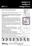
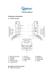
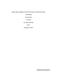
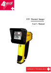
pirsensor
ceiling mount pirsensor fitting & operating instructions
RATING AT 240V AC
Product: 374A-1, 374A-2 Three wire.
Incandescent
Fluorescent
Compact
Fluorescent
Resistive
Time Delay
The ceiling mount pirsensor is part of the Elkay family of switches, timers and detectors
which save energy and increase convenience in and around your home, garden or premises.
USAGE
16A
16A
16A
16A
2mins - 2hours.
The PIR sensor has been
LIVE IN
designed to replace a single
NEUTRAL
gang light switch, to control
lighting, heating and
LIVE OUT
ventilation. The unit is
switched on by the
DIL
detection of moving body
SWITCHES
heat within a specified
range. When body heat is
no longer detected, the
LUX LEVEL
ADJUSTMENT
unit will switch off after
the adjustable time period
Diagram 1
has elapsed. If moving body
heat is detected again during the timing period, the timing sequence will restart.
The unit has a lux level adjustment, which measures the ambient light levels and
prevents lighting being switched on when there is sufficient light in the room.
POSITIONING
7 metres approx.
FLOOR
7 metres approx.
CEILING
2.4 metres
Use the detection range to determine a suitable location
for the sensor. When locating the position of the unit
avoid subjecting the sensor to direct sunlight. Ensure that
the sensor is not adjacent to the load. Do not site the
unit on a vibrating surface, or near a forced air heating or
ventilation. (see diagram 2)
L
Diagram
2
MOUNTING AND INSTALLATION
Important Please note that it is essential that the Live In wire and switch Live Out is identified prior to commencing
installation. Turn off mains supply for installation.
Step 1 Cut a hole measuring 64mm in diameter in the chosen area for the sensor. Please see positioning.
Step 2 Place the Live In wire into the left hand position of the connector, the switched Live Out wire into the second from
left position of the connector and neutral into right hand position of connector. (see diagram 1)
Step 3 Fold the two arms up into the vertical position and insert unit into hole. Release unit ensuring arms are securely in
place.
Step 4 To set time, as per timing table, remove fascia ring by turning anti-clockwise one quarter turn to access switches one
through four. Depending on required time available from 2 minutes to 2 hours. E.g 10 minutes = switch one – off, switch two
– on, switch three – off, switch four – off. (see diagram 3)
Elkay Electrical, Coleshill, Birmingham, England.
Tel: +44 (0) 1675 468222 www.elkay.co.uk
Patent Pending Inst. Ref. No PIRC301 Rev. No.: 04/07
4.
20 mins
15 mins
4.
4.
25 mins
4.
3.
2.
2.
2.
2.
2.
2.
50 mins
1.
60 mins
1.
70 mins
1.
80 mins
1.
90 mins
ON
3.
ON
3.
ON
3.
ON
3.
1.
100 mins
1.
30 mins
4.
DIP
4.
3.
2.
ON
1.
3.
1.
DIP
2.
ON
2.
1.
40 mins
DIP
4.
1.
3.
4.
3.
3.
2.
2.
1.
110 mins
ON
10 mins
1.
DIP
4.
DIP
5 mins
1.
DIP
1.
DIP
1.
4.
3.
DIP
2.
4.
ON
2.
DIP
2.
ON
2.
ON
2.
ON
3.
ON
4.
3.
DIP
DIP
DIP
DIP
DIP
4.
3.
ON
DIP
4.
3.
2 mins
ON
4.
3.
ON
ON
DIP
4.
1.
120 mins
Diagram 3
MOUNTING AND INSTALLATION CONTINUED
Step 5 To adjust lux level (i.e the ambient light level at which you would like your lights to be activated via the PIR sensor)
please refer to the lux level rotary adjuster diagram. Rotate the lux level adjustment clockwise to decrease the level of light
required to turn the lights on and anticlockwise to increase the level of light required to turn the lights on. See diagram 1 for
position of lux level adjustment. Replace fascia ring by turning clockwise one quarter turn.
INSTALLATION NOTES
N.B After installation the PIR will require approximately 5 minutes to initialise.
OPERATION
1. In standard operation, the PIR will now sense body heat when passing through the detection zone. Each time the PIR is
triggered it will reset the timer back to the start of the timing period. The unit will then wait 20 seconds approximately
before allowing the PIR unit to sense and re-trigger the timing period again.
2. If no one is present in the room or the detection zone is not passed through, during its set time period the timer will time
out, turning off the lights or appliance.
3. The PIR unit will only trigger the lights or appliance if the ambient light level is below that set on the lux level adjustment.
IMPORTANT NOTICE
All wiring should be carried out by a competent person or a qualified Electrician in accordance with the current IEE Wiring
Regulations. If unit is faulty return to place of purchase.
TECHNICAL HELPLINE
For further help, or information on this and the other products in the Elkay range visit www.elkay.co.uk or call 01675 468222.
Elkay Electrical, Coleshill, Birmingham, England.
Tel: +44 (0) 1675 468222 www.elkay.co.uk
Patent Pending Inst. Ref. No PIRC301 Rev. No.: 04/07