1
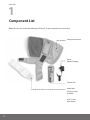
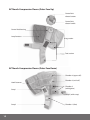
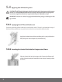
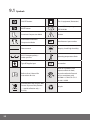
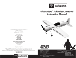
ACTitouch
TM
Adaptive Compression Therapy
User’s Guide
TM
Table of Contents
Chapter 1
Chapter 6
Component List. . . . . . . . . . . . . . . . . . . . . . . . . . . . . . 2
Wound Dressings. . . . . . . . . . . . . . . . . . . . . . . . . . . . 19
Chapter 2
Chapter 7
Product Description . . . . . . . . . . . . . . . . . . . . . . . . . 3
2.1 Sustained Compression Mode. . . . . . . . . . 4
2.2 Intermittent Pneumatic
Compression Mode. . . . . . . . . . . . . . . . . . . . 5
Cleaning, Care and Maintenance . . . . . . . . . . . . 20
7.1 Cleaning and Disinfecting. . . . . . . . . . . . . 20
7.2 Storage and Handling. . . . . . . . . . . . . . . . . 22
7.3 Maintenance and Service . . . . . . . . . . . . . 22
7.4 Disposal. . . . . . . . . . . . . . . . . . . . . . . . . . . . . . 22
Chapter 3
Warnings and Cautions. . . . . . . . . . . . . . . . . . . . . . 6
3.1 Warnings. . . . . . . . . . . . . . . . . . . . . . . . . . . . . . 6
3.2 Cautions. . . . . . . . . . . . . . . . . . . . . . . . . . . . . . . 7
Chapter 4
Indications and Contraindications. . . . . . . . . . . 8
4.1 Indications . . . . . . . . . . . . . . . . . . . . . . . . . . . . 8
4.2 Contraindications. . . . . . . . . . . . . . . . . . . . . . 8
Chapter 5
Directions for Use. . . . . . . . . . . . . . . . . . . . . . . . . . . . . 9
5.1 Functional Controls. . . . . . . . . . . . . . . . . . . . 9
5.2 First Use. . . . . . . . . . . . . . . . . . . . . . . . . . . . . . 11
5.3 Charging the Device. . . . . . . . . . . . . . . . . . 11
5.4Applying the ACTitouch System. . . . . . . 12
5.5Switching On the ACTitouch System
in Sustained Compression Mode . . . . . . 16
5.6
Muted Operation in Sustained
Compression Mode. . . . . . . . . . . . . . . . . . . 16
5.7Intermittent Pneumatic
Compression Mode. . . . . . . . . . . . . . . . . . . 17
5.8Switching Off the ACTitouch System. . . 18
5.9Removing the ACTitouch System. . . . . . 18
Chapter 8
Troubleshooting Guide. . . . . . . . . . . . . . . . . . . . . . 23
8.1 Limited Warranty for Home Use . . . . . . . 27
8.2 Obtaining Replacement
Products and Service. . . . . . . . . . . . . . . . . . 28
8.3 Limited Warranty and Service
for Facility Use. . . . . . . . . . . . . . . . . . . . . . . . 28
8.4Patents. . . . . . . . . . . . . . . . . . . . . . . . . . . . . . . 28
8.5 Product Development and
Quality Improvement. . . . . . . . . . . . . . . . . 28
Chapter 9
Technical Information . . . . . . . . . . . . . . . . . . . . . . . 29
9.1Symbols. . . . . . . . . . . . . . . . . . . . . . . . . . . . . . 30
9.2 Electromagnetic Interference. . . . . . . . . 32
1
1
Chapter
Component List
Before first use, ensure that the following ACTitouch™ System components are accessible:
Compression Sleeve
Power
Adapter/Charger
Control Unit
Undersocks
(Three [3] socks
included)
User’s Guide
(Not shown)
2
2
Chapter
Product Description
The ACTitouch System applies pneumatic compression to the lower leg, ankle, and foot.
It consists of four (4) main parts:
1. T he Compression Sleeve consists of four (4) chambers that inflate with air to apply pressure to the leg.
Its simple wrap-around design with hook and loop fasteners means the Compression Sleeve can be
fitted to many differently shaped legs and can be applied and removed with ease.
2. T he Control Unit fits into the Compression Sleeve during device use. It monitors and adjusts the air
pressure to ensure the correct level of compression is applied to the leg.
3. T he Undersock is designed to draw perspiration and moisture away from the skin and has padding in
key areas to provide additional comfort.
4. T he Power Adapter/Charger is used to power the device directly or to charge the battery for
ambulatory use.
The device has two (2) modes of operation: Sustained Compression Mode and Intermittent Pneumatic
Compression Mode.
3
2.1 Sustained Compression Mode
In this mode, the device provides sustained, graduated pneumatic compression to the leg at preset
pressures, while powered by its own rechargeable battery. When it is first switched on, the device
gradually inflates, starting at the foot and working up toward the knee. Each chamber will stop inflating
when the correct pressures are achieved and will hold these pressures until the device is turned off.
Every half hour, the pressures are automatically checked and readjusted, if necessary. The patient may
hear the pump running for a few seconds while the pressure is being checked. In this mode, the patient
is free to move around and carry out normal activities (See Chapter 3 Warnings and Cautions).
Pressure Changes During
Sustained Compression Mode
Chamber 1
Chamber 2
Chamber 3
Chamber 4
45
40
Pressure (mmHg)
35
30
25
20
15
10
5
0
Time
When operating in Sustained Compression
Mode,
and absolute
quiet is necessary (e.g., at the theater),
Pressure
Changes
During
a MUTE button can be used to
pause the pump
(See Section
5.6 MutedMode
Operation in Sustained
Intermittent
Pneumatic
Compression
Compression Mode). While muted,
the
device
will
remain
inflated
to
apply
to the leg but will
Chamber 1
Chamber 2
Chamber 3
Chamberpressure
4
no longer adjust the pressure.
55
50
Pressure (mmHg)
IMPORTANT: The device will automatically reset to normal operation after two (2) hours
45
of
muted use.
40
35
30
25
20
15
10
5
0
Time
4
Pressure Changes During
Sustained Compression Mode
2.2 Intermittent Pneumatic Compression Mode
Chamber 1
Chamber 2
Chamber 3
Chamber 4
45
40
Pressure (mmHg)
When in Intermittent
35 Pneumatic Compression Mode, the device will perform cyclic inflation/deflation
sequences to preset30gradient pressures. To operate in this mode, the Control Unit requires power
from the Power Adapter/Charger.
When the device is first plugged in and switched on, it will initially
25
inflate to a low pressure
in
each
chamber.
Once the starting pressure is reached, each chamber will
20
inflate in sequence,15
starting at the foot and working up toward the knee until all of the chambers
reach the intended 10
pressure levels. All four (4) chambers will then deflate to the low pressure level.
This cycle of inflation5 and deflation will continue until the device is either unplugged from the Power
Adapter/Charger or after two (2) hours of use. When the device is operating in Intermittent Pneumatic
0
Compression Mode, the patient should remain seated,
Time reclining, or lying down.
Pressure Changes During
Intermittent Pneumatic Compression Mode
Chamber 1
Chamber 2
Chamber 3
Chamber 4
55
50
45
Pressure (mmHg)
40
35
30
25
20
15
10
5
0
Time
5
3
Chapter
Warnings and Cautions
3.1 Warnings
•Please read all of the information provided before use and ensure that all instructions are followed.
•Electrical equipment may be hazardous if misused. Do not open or take apart the ACTitouch
Control Unit for any reason or the warranty will be voided. There are no customer serviceable parts
in this device.
•Prior to use, the patient should be fully assessed by a healthcare professional for treatment
suitability, trained on the use of the device, and advised on optimal wear time in each mode.
•Failure to wear the device as recommended, even for short periods, may delay ulcer healing or may
negatively impact treatment outcomes.
•Use the ACTitouch Control Unit or ACTitouch Compression Sleeve only with the ACTitouch
Undersock and Power Adapter/Charger. Do not use the ACTitouch System while wearing other
compression products.
•Treatment should be stopped if additional pain, tingling or numbness of the limb occurs during,
or as a result of treatment.
•The Undersock should not be placed in direct contact with an open wound. It is recommended
that this device be used in conjunction with an appropriate absorptive moisture retentive wound
dressing, applied before the ACTitouch System.
•Caution should be taken when using the ACTitouch System on fragile skin.
•Do not operate motor vehicles or other machinery while wearing the ACTitouch System. Consult
with your healthcare provider about compression options when not wearing the ACTitouch System.
•Ensure the electrical supply to the device is switched off by disconnecting it from the Power
Adapter/Charger before cleaning or disinfecting.
•The ACTitouch System should be removed before bathing or showering. Reapply the device
immediately afterward, ensuring the skin is dried prior to application.
• Do not walk with the Power Adapter/Charger attached to the device.
6
3.2 Cautions
•Regularly check the status indicator located at the top of the control unit while using ACTitouch.
The green light on the Control Unit indicates the control unit is charged and on. A flashing
red status light (and periodic audible alarm) indicates that battery power is low. No light indicates
the power is off.
• Ensure that the device is clean and dry prior to storage.
•Do not immerse the ACTitouch System in water, or spill liquid on the Control Unit. The device is
not waterproof, and exposure to liquid may damage the Control Unit or Compression Sleeve. If the
device becomes soaked with fluid, discontinue use of the device.
• Do not allow the Compression Sleeve to come into contact with sharp objects.
•Do not expose the Undersock, Compression Sleeve or Control Unit to excessive heat or open flames,
such as cigarettes, portable heaters, etc.
7
4
Chapter
Indications and Contraindications
Rx Only
U.S. Federal law restricts this device to sale by, or on the order of, a licensed healthcare professional.
4.1 Indications
The ACTitouch System provides graduated compression in both sustained and intermittent
settings for use in:
•
Enhancing venous return;
•
Reducing venous leg ulcer healing time;
•
Treatment and promotion of healing of stasis dermatitis and venous stasis ulcers;
•
Treatment of chronic venous insufficiency;
•
Reducing edema due to venous stasis;
•
Treatment of lymphedema.
4.2 Contraindications
The ACTitouch System is contraindicated if the patient has:
• An Ankle Brachial Pressure Index of less than 0.8;
• Diagnosed or suspected acute Deep Vein Thrombosis (DVT) or pulmonary embolism;
• Pulmonary edema;
• Leg gangrene;
• Acute thrombophlebitis;
• Decompensated/Congestive Cardiac Failure;
• Severe arteriosclerosis or other ischemic vascular disease;
• Diabetes in association with peripheral arterial disease;
• Acute infections of the skin such as cellulitis;
• Any lower limb malignancy.
8
5
Chapter
Directions for Use
•The ACTitouch System should be worn as recommended and prescribed by the physician. The
usual prescribed duration of use will range from 10 to 14 hours per day, including both Sustained
Compression and Intermittent Pneumatic Compression Modes.
•The device should be applied immediately upon waking and worn throughout the day. The
ACTitouch System should be removed for bathing or showering, and when driving or operating
machinery. Reapply the device immediately after these activities.
•The device should be removed just prior to going to bed and recharged (See Section 5.3 Charging the
Device). Consult with your healthcare provider about other compression options during sleep.
IMPORTANT: Failure to wear the device as recommended, even for short periods, may
delay
ulcer healing or may negatively impact treatment outcomes.
5.1 Functional Controls
ACTitouch Control Unit
Status indicator
Charging port
ON/OFF button
MUTE button
Liquid crystal display (LCD)
9
ACTitouch Compression Sleeve (Outer Face Up)
Control Unit
release buttons
Control Unit
release handle
Control Unit housing
Loop fasteners
Leg section
Foot section
ACTitouch Compression Sleeve (Outer Face Down)
Chamber 4 (upper calf )
Hook fasteners
Strap 1
Chamber 3 (mid calf )
Chamber 2
(ankle/gaiter)
Strap 2 (ankle strap)
Strap 3
10
Chamber 1 (foot)
5.2 First Use
Remove all device components from the packaging and fully charge the device as indicated in
Section 5.3 Charging the Device.
5.3 Charging the Device
Before each daily use, the ACTitouch System should be fully charged. It is recommended that the device
be charged every night for a minimum of four (4) hours. The Control Unit should remain inserted in the
Compression Sleeve while charging.
•Ensure that the Power Adapter/Charger is connected to a working AC power outlet. A green light will
illuminate on the Power Adapter/Charger when it is correctly connected.
•Plug the supplied Power Adapter/Charger into the charging port on the Control Unit. If this is done
correctly, the green status indicator on the Control Unit will illuminate.
•Charge the unit for a minimum of four (4) hours, even if the status indicator on the Control Unit is
showing green. The status indicator flashes red when the battery charge is low. Immediate charging
is required. The normal battery life between charges is sixteen (16) hours.
• The device will be fully charged after four (4) hours. Nightly charging is recommended.
If the Control Unit is stored unused for prolonged periods of time, the Control Unit should be fully
charged at least once every six (6) months. This will ensure that a good battery life is maintained.
IMPORTANT: To ensure an adequate supply of power while wearing the device, please
ensure that you charge the device at the end of each day. Charge whether the status
indicator is showing green or flashing red.
Use only the Power Adapter/Charger provided with your ACTitouch System for charging
the Control Unit and for Intermittent Pneumatic Compression Mode operation.
The batteries are not user replaceable.
11
5.4 Applying the ACTitouch System
Caution: The ACTitouch Undersock should not be placed in direct contact with an open
wound. It is recommended that this device be used in conjunction with an appropriate
wound dressing before the device is applied (See Chapter 6 Wound Dressings).
IMPORTANT: Patients are advised to apply the device before putting on clothing over the
leg and foot.
5.4.1 Applying the ACTitouch Undersock
For correct positioning of the Undersock, ensure that the word “ACTitouch” is positioned on the top of
the foot and the padded areas are positioned over the shin and around the heel and ankle.
Apply the Undersock over the foot, and then pull it up to just below the
knee, taking care not to displace any wound dressing.
5.4.2 Inserting the Control Unit into the Compression Sleeve
Slide the Control Unit into its housing on the Compression Sleeve until
a click is felt and heard; the Control Unit is then secured correctly within
the sleeve.
12
Correct placement
Verify the Control Unit is correctly assembled by checking to see if the
blue markings are visible on the front of the Control Unit. If they are
visible, the Control Unit is not fully secure.
Incorrect placement
IMPORTANT: For correct functioning of the device, ensure that the Control Unit is correctly
inserted in the Compression Sleeve.
The patient should leave the Control Unit inserted into the Compression Sleeve at all times.
The battery can be charged without removing the Control Unit from the Compression Sleeve.
5.4.3 Applying the Compression Sleeve
Place the Compression Sleeve on the floor, outer face
downward so that the chambers can be seen, with strap
2 (ankle strap) pointing toward the wearer, regardless of
whether the Compression Sleeve is to be applied to the
right or left leg.
Place the arch of the foot over chamber 1 (marked with an
arrow on the Compression Sleeve) with the toes pointing
in the direction of the arrow.
Strap 3
Strap 2 (ankle strap)
Strap 1
13
Wrap strap 1 over the top of the foot and secure in place by wrapping
strap 2 (ankle strap) around the ankle and placing over strap 1.
Strap 2 (ankle strap)
Strap 1
Strap 3
Wrap strap 3 over the top of the foot and secure in place over straps 1 and 2.
Strap 3
The correctly applied foot section will appear as shown.
Once the foot section is fastened, lift the leg section of the Compression
Sleeve and drape over the leg with the Control Unit and “ACTitouch” logo
positioned over the shin.
14
Wrap the loop fasteners around the back of the calf.
Fix the loop fasteners securely in place with the hook fasteners.
Ensure that fasteners are adjusted to give a close fit between the
Compression Sleeve and the leg and foot.
The correctly applied ACTitouch System will appear as shown.
W
ARNING: When applied, the top of the Compression Sleeve should be at least 2.5cm below
the crease of the knee when seated.
IMPORTANT: Always ensure that the Compression Sleeve is applied in the correct position
with the Control Unit on the front of the leg over the shin.
Applying the sleeve too loosely may result in the unit switching off.
15
5.5 Switching On the ACTitouch System in Sustained Compression Mode
IMPORTANT: If footwear is to be worn during the treatment session, it is advisable for the
to put on footwear prior to switching on the ACTitouch System.
wearer
Do not switch on the device in Sustained Compression Mode unless it is applied to the leg.
•Ensure that the Control Unit is correctly inserted in the Compression Sleeve, that the Compression
Sleeve is correctly applied to the leg, and that the Power Adapter/Charger is not connected.
•While seated, press and hold the ON/OFF button until the status indicator illuminates (approximately
two [2] seconds). The ON/OFF button can then be released.
•The Compression Sleeve will now inflate. It may take up to five (5) minutes to completely inflate the
Compression Sleeve. Remain seated during inflation. To ensure a better fit, pull up and support the
Compression Sleeve in place while the chambers inflate.
•The Control Unit is programmed to inflate the chambers of the Compression Sleeve to preset
pressures. When the correct pressures are reached, the Control Unit will stop pumping.
•When the Compression Sleeve is fully inflated, the patient may stand up and resume normal
activities. (See Chapter 3 Warnings and Cautions.)
•The MUTE button may be used in Sustained Compression Mode once the Compression Sleeve is fully
inflated. (See Section 5.6 Muted Operation in Sustained Compression Mode for details.)
5.6 Muted Operation in Sustained Compression Mode
•To activate muted operation during Sustained Compression Mode, press the MUTE button and
hold for at least two (2) seconds. Upon release of the MUTE button, the Control Unit will make a
subtle beep sound.
IMPORTANT: While muted, the device will remain inflated to apply pressure to the leg but
will no longer adjust the pressure.
•To deactivate muted operation, press the MUTE button again (for at least two [2] seconds). Upon
release of the MUTE button, the Control Unit will make a subtle beep sound. The pump will now
restart and, if necessary, readjust all chambers back to the correct pressures.
•If muted operation is not manually deactivated, then the device will automatically switch back to
Sustained Compression Mode operation after two (2) hours.
16
5.7 Intermittent Pneumatic Compression Mode
In Intermittent Pneumatic Compression Mode, the device will operate a cyclic pulsed inflation/deflation
sequence until either it is unplugged from the Power Adapter/Charger, or two (2) hours have elapsed,
at which point the device will switch back to Sustained Compression Mode operation.
It is recommended that the Intermittent Pneumatic Compression Mode be used for at least two (2)
hours per day. When using in Intermittent Pneumatic Compression Mode, the user should be either
seated or lying down; not standing. This can be for:
• One (1) session of two (2) hours OR
• Two (2) one-hour (1-hour) sessions.
• Any session should be a minimum of 30 minutes.
It is recommended that the Intermittent Pneumatic Compression Mode be used late in the user’s day
when swelling would be the greatest, and when the user is less active and can sit, recline, or lie down.
To operate in Intermittent Pneumatic Compression Mode for longer than two (2) hours in succession,
the Intermittent Pneumatic Compression Mode may be re-activated after the device automatically
switches back into Sustained Compression Mode. For advice on optimal wear time in Intermittent
Pneumatic Compression Mode, please consult a healthcare professional. Failure to use the device as
recommended may delay ulcer healing or may negatively impact treatment outcomes.
CAUTION: Do not walk while the device is operating in Intermittent Pneumatic
Compression Mode.
5.7.1 To Activate Intermittent Pneumatic Compression Mode
from Sustained Compression Mode Operation
•Plug the supplied Power Adapter/Charger into the charging port on the Control Unit.
•Ensure that the Power Adapter/Charger is connected to an AC power outlet. A green light will
illuminate on the Power Adapter/Charger if it is correctly connected to the power supply.
•Press the ON/OFF button for at least two (2) seconds. Upon release of the ON/OFF button,
Intermittent Pneumatic Compression Mode will be activated and the pump will start.
IMPORTANT: Do not switch the device into Intermittent Pneumatic Compression Mode
unless the Compression Sleeve is applied to the leg.
17
5.7.2 To Activate Intermittent Pneumatic Compression Mode from Off:
•
Apply the Compression Sleeve (See Section 5.4.3 Applying the Compression Sleeve).
•
Plug the supplied Power Adapter/Charger into the charging port on the Control Unit.
•Ensure that the Power Adapter/Charger is connected to a working AC power outlet. A green light
will illuminate on the Power Adapter/Charger if it is correctly connected to the power supply.
•Press the ON/OFF button for at least two (2) seconds. Upon release of the ON/OFF button
Intermittent Pneumatic Compression Mode will be activated and the pump will start.
5.8
•
Switching Off the ACTitouch System
Ensure that the Power Adapter/Charger is not attached to the charging port.
•Press and hold the ON/OFF button for at least two (2) seconds. On release of the ON/OFF button, the
device will now deflate all chambers and automatically switch itself off.
IMPORTANT: The ACTitouch System device may automatically switch off on rare occasions
if
prolonged high pressure is detected by the device. This could occur if high pressure
is applied externally to the sleeve. This is a safety feature of the device, which may
be restarted in the normal way (See Section 5.5 Switching On the ACTitouch System in
Sustained Compression Mode). If the device switches off repeatedly, refer to Chapter 8
Troubleshooting Guide.
5.9 Removing the ACTitouch System
•To remove the device, reverse the procedure outlined in Section 5.4 Applying the ACTitouch System.
•If required, clean the Compression Sleeve according to the cleaning instructions in Chapter 7
Cleaning, Care and Maintenance.
•Wash the Undersock according to the cleaning instructions in Chapter 7 Cleaning, Care
and Maintenance.
IMPORTANT: The patient should leave the Control Unit inserted into the Compression
Sleeve at all times.
The battery can be charged without removing the Control Unit from the Compression Sleeve.
18
6
Chapter
Wound Dressings
The ACTitouch System should be used in conjunction with an appropriate wound dressing
as recommended by your clinician. Apply the dressing to the wound before applying the
ACTitouch Undersock.
Please follow the dressing manufacturer’s instructions for use. Appropriate tape or a light retention
stocking may aid dressing retention.
The primary dressing over the ulcer should be changed when clinically indicated. Typically dressings
will require changing when they are moistened, as can occur if your wound is leaking any fluid or if the
dressing becomes wet after bathing or showering.
Remove the ACTitouch System prior to showering. If you do not wish to change the dressing when
showering, cover the dressing with a waterproof outer layer.
19
7
Chapter
Cleaning, Care and Maintenance
Please refer to Chapter 3 Warnings and Cautions. Switch off and disconnect the Power Adapter/Charger
before cleaning or disinfecting.
7.1 Cleaning and Disinfecting
7.1.1 Cleaning the ACTitouch Undersock
IMPORTANT: The ACTitouch Undersock is intended for single patient use only.
It is recommended that the ACTitouch Undersock be replaced after a maximum of 60
washes. To purchase additional socks please contact Customer Service at 866.435.3948.
Machine wash hot on a gentle cycle
Air dry or tumble dry on a low-temperature setting
Do not iron
Do not use chlorine-based bleach
Do not dry clean
20
7.1.2 Cleaning and Disinfecting the ACTitouch Compression Sleeve
WARNING: Switch off and disconnect the Power Adapter/Charger before inspecting, cleaning or
disinfecting. Failure to comply could result in electric shock.
To clean, wipe down with a soft cloth dampened with mild soap and water. Do not
immerse in fluids. Air dry thoroughly.
Do not machine wash
Do not tumble dry
Do not iron
Do not dry clean
The ACTitouch Compression Sleeve should be disinfected anytime there are biological contaminants or
visible stains. After cleaning, wipe down with an isopropyl alcohol- or water-based antimicrobial wash
with a soft cloth or pad. Do not immerse in fluid. Do not steam-sterilize.
For device use in multi-patient situations, it is important to minimize cross-contamination by
disinfecting the ACTitouch system between patients’ usage. To disinfect the Compression Sleeve, wipe
down with an isopropyl alcohol- or water-based antimicrobial wash with a soft cloth or pad. Do not
immerse in fluid. Do not steam-sterilize.
Do not clean or disinfect with household detergents, abrasive cleaners, scourers,
degreasers, solvents, bleach or phenol-based agents, such as trichlorophenol (TCP).
7.1.3 Cleaning and Disinfecting the ACTitouch Control Unit
WARNING: Switch off and disconnect the Power Adapter/Charger before inspecting, cleaning or
disinfecting. Failure to comply could result in electric shock.
To clean, wipe down with a soft cloth dampened with mild soap and water. Do not
immerse in fluids. Air dry thoroughly.
21
The ACTitouch Control Unit should be disinfected anytime there are biological contaminants or visible
stains. After cleaning, wipe down with an isopropyl alcohol- or water-based antimicrobial wash with a
soft cloth or pad. Do not immerse in fluid. Do not steam-sterilize.
For device use in multi-patient situations, it is important to minimize cross-contamination by
disinfecting the ACTitouch system between patients’ usage. To disinfect the Control Unit, wipe down
with an isopropyl alcohol- or water-based antimicrobial wash with a soft cloth or pad. Do not immerse
in fluid. Do not steam-sterilize.
Do not clean or disinfect with household detergents, abrasive cleaners, scourers,
degreasers, solvents, bleach or phenol-based agents, such as trichlorophenol (TCP).
7.2 Storage and Handling
It is recommended that the ACTitouch System be stored at room temperature. Avoid excessive heat and
cold. Do not store device in direct sunlight. Ensure that the device is clean and dry prior to storage.
Reasonable care should be taken when handling and using the ACTitouch System. Although the
device has been designed for everyday use, heavy impacts, contact with sharp objects and rough
handling should be avoided. Do not immerse the device in fluid. If either the Compression Sleeve or
Control Unit become soaked with fluid or otherwise damaged, do not use the device.
7.3 Maintenance and Service
The ACTitouch System is designed to be maintenance free; routine service is not required.
CAUTION: Do not open or take apart the ACTitouch Control Unit for any reason. There are no
customer serviceable parts in the ACTitouch System.
7.4 Disposal
For disposal of any components of the ACTitouch System, please follow local waste regulations or
consult your local institutional waste-management service or municipal waste authority.
22
8
Chapter
Troubleshooting Guide
The following table provides a troubleshooting guide for the ACTitouch System in the unlikely
event of a malfunction. Please refer to Section 8.2 Obtaining Replacement Products and Service
for additional information.
Problem
The Compression
Sleeve is not
inflating or deflating
as expected.
The Compression
Sleeve is difficult to
fasten securely.
Possible Cause
Corrective Action
1. The Control Unit has not been
securely inserted into the
Compression Sleeve.
1. Refer to Section 5.4.2 Inserting the Control
Unit into the Compression Sleeve.
2. The Control Unit needs to
be charged.
2. C
harge the Control Unit. Refer to
Section 5.3 Charging the Device.
3. T he Control Unit has not been
switched on.
3. S witch the Control Unit on. Refer to
Section 5.5 Switching On the ACTitouch
System in Sustained Compression Mode.
4. T he MUTE button has been
activated while operating in
sustained mode.
4. D
eactivate muted operation. Refer to
Section 5.6 Muted Operation in Sustained
Compression Mode Operation.
5. Device fault.
5. P
lease call customer service at (toll-free)
866.435.3948.*
1. An incorrectly sized Compression
Sleeve has been selected.
1. Please call customer service at (toll-free)
866.435.3948.*
2. T he Compression Sleeve is
already partially inflated prior to
application to the limb.
2. Switch the Control Unit on. Prior to full
inflation of the Compression Sleeve, switch
the Control Unit off again to evacuate any
air present in the sleeve.
3. T he Compression Sleeve hook
or loop fastening areas have been
contaminated with foreign bodies
(debris, such as lint or hair.)
3. I nspect the Compression Sleeve fastening
areas and remove any fluff or similar
foreign bodies.
4. Device fault.
4. P
lease call customer service at (toll-free)
866.435.3948.*
*Customer service can be contacted at 866.435.3948 (toll-free) between 8:00 am – 5:00 pm CT,
Monday through Friday.
23
Problem
The Control Unit
will not operate in
Sustained
Compression Mode.
The Control Unit
does not respond
to buttons being
pressed.
Possible Cause
Corrective Action
1. T he Control Unit has not been
securely inserted into the
Compression Sleeve.
1. R
efer to Section 5.4.2 Inserting the Control
Unit into the Compression Sleeve.
2. The Control Unit needs to
be charged.
2. C
harge the Control Unit. Refer to Section
5.3 Charging the Device.
3. T he Control Unit has not been
switched on.
3. S witch the Control Unit on. Refer to
Section 5.5 Switching On the ACTitouch
System in Sustained Compression Mode.
4. T he MUTE button has been
activated.
4. D
eactivate muted operation. Refer to
Section 5.6 Muted Operation in Sustained
Compression Mode Operation.
5. The event log needs to be reset.
5. R
emove the Control Unit from the
Compression Sleeve. Reset the device by
pressing and holding the MUTE button for
ten (10) seconds. The LCD will flash “–––”
to indicate a successful event log reset,
and the unit will switch off. The Control
Unit may now be reinserted into the
Compression Sleeve and used as normal.
6.Device fault.
6. P
lease call customer service at (toll-free)
866.435.3948.*
1. T he Control Unit needs to
be charged.
1. C
harge the Control Unit. Refer to Chapter
5.3 Charging the Device.
2. T he Control Unit has not been
switched on.
2. S witch the Control Unit on. Refer to
Chapter 5.5 Switching On the ACTitouch
System in Sustained Compression Mode.
3. The event log needs to be reset.
3. R
emove the Control Unit from the
Compression Sleeve. Reset the device by
pressing and holding the MUTE button for
ten (10) seconds. The LCD will flash “–––”
to indicate a successful event log reset,
and the unit will switch off. The Control
Unit may now be reinserted into the Compression Sleeve and used as normal.
4. Device fault.
4. P
lease call customer service at (toll-free)
866.435.3948.*
5. Control Unit does not respond to
the button being pressed.
5. H
old button down for a longer period of
time (e.g., Two [2] seconds)
*Customer service can be contacted at 866.435.3948 (toll-free) between 8:00 am – 5:00 pm CT,
Monday through Friday.
24
Problem
The Control Unit
will not operate
in Intermittent
Pneumatic
Compression Mode.
The Compression
Sleeve appears to be
leaking air.
Possible Cause
Corrective Action
1. T he Control Unit has not been
securely inserted into the
Compression Sleeve.
1. Refer to Section 5.4.2 Inserting the Control
Unit into the Compression Sleeve.
2. T he Power Adapter/Charger is
not securely connected to the
charging port and an AC
power outlet.
2. E nsure the Power Adapter/Charger is
securely connected to the charging port
and power supply. A green light will
illuminate on the Power Adapter/Charger
if it is correctly connected to an AC
power outlet.
3. T he Control Unit has not been
switched on.
3. S witch the Control Unit on. Refer to Section
5.7.1 To Activate Intermittent Pneumatic
Compression Mode from Sustained
Compression Mode Operation and Section
5.7.2 To Activate Intermittent Pneumatic
Compression Mode from Off.
4. The event log needs to be reset.
4. R
emove the Control Unit from the
Compression Sleeve. Reset the device by
pressing and holding the MUTE button for
ten (10) seconds. The LCD will flash “–––”
to indicate a successful event log reset,
and the unit will switch off. The Control
Unit may now be reinserted into the
Compression Sleeve and used as normal.
5. Device fault.
5. P
lease call customer service at (toll-free)
866.435.3948.*
1. T he Control Unit has not been
securely inserted into the
Compression Sleeve.
1. R
efer to Section 5.4.2 Inserting the Control
Unit into the Compression Sleeve.
2. Device fault.
2. I f sleeve is damaged, call customer service
at (toll-free) 866.435.3948* for replacement.
*Customer service can be contacted at 866.435.3948 (toll-free) between 8:00 am – 5:00 pm CT,
Monday through Friday.
25
Problem
The device is
frequently
“locking out.”
The Control Unit
power does not last a
full day.
There is a change
in performance of
the device.
The device turns off
unexpectedly.
Possible Cause
Corrective Action
1. The event log needs to be reset.
1. R
emove the Control Unit from the
Compression Sleeve. Reset the device by
pressing and holding the MUTE button for
ten (10) seconds. The LCD will flash “–––”
to indicate a successful event log reset,
and the unit will switch off. The Control
Unit may now be reinserted into the
Compression Sleeve and used as normal.
2. Multiple “lockouts” may be a
device fault.
2. P
lease call customer service at (toll-free)
866.435.3948.*
1. T he Control Unit needs to
be charged.
1. C
harge the Control Unit. Refer to Section 5.3
Charging the Device.
2. Device fault.
2. P
lease call customer service at (toll-free)
866.435.3948.*
1. T he Control Unit has not been
securely inserted into the
Compression Sleeve.
1. R
efer to Section 5.4.2 Inserting the Control
Unit into the Compression Sleeve.
2. Device fault.
2. P
lease call customer service at (toll-free)
866.435.3948.*
1. Automatic shutdown
due to temporary event.
1. S witch the Control Unit back on. Refer to
Section 5.5 Switching On the ACTitouch
System in Sustained Compression Mode.
2. T he Control Unit needs to
be charged.
2. C
harge the Control Unit. Refer to Section 5.3
Charging the Device.
3. Auto shutdown and lock out.
3. R
emove the Control Unit from the
Compression Sleeve. Reset the device by
pressing and holding the MUTE button for
ten (10) seconds. The LCD will flash “–––”
to indicate a successful event log reset,
and the unit will switch off. The Control
Unit may now be reinserted into the
Compression Sleeve and used as normal.
4. Device fault.
4. P
lease call customer service at (toll-free)
866.435.3948.*
*Customer service can be contacted at 866.435.3948 (toll-free) between 8:00 am – 5:00 pm CT,
Monday through Friday.
26
8.1 Limited Warranty for Home Use
Tactile Medical (TM) provides a warranty for the ACTitouch System. The ACTitouch Control Unit is
warranted to be free from defects in material and workmanship for a period of one (1) year from the
date of purchase. The ACTitouch Compression Sleeve is warranted to be free from defects in material
and workmanship for a period of three (3) months from the date of purchase. All other accessories
and supplies related to the use of the ACTitouch System are warranted to be free from defects in
material and workmanship for their first use. TM’s sole obligation in the event of a breach of this
warranty is expressly limited to the replacement of defective parts that cannot, in the sole discretion
of TM, be repaired. Replacement parts may be new or refurbished parts as solely determined by TM.
No representation or other affirmation of fact set forth in this agreement, including but not limited to
statements regarding suitability for use or performance of the ACTitouch System, shall be deemed to
be a warranty or representation by TM for any purpose, nor give rise to any liability or obligation of TM.
EXCEPT FOR THE FOREGOING, TM MAKES NO OTHER WARRANTY. THE WARRANTIES SET FORTH HERE
ARE IN LIEU OF ALL OTHER WARRANTIES, EXPRESSED OR IMPLIED, WHICH ARE HEREBY DISCLAIMED
AND EXCLUDED BY THE MANUFACTURER, INCLUDING WITHOUT LIMITATION ANY WARRANTY OF
MERCHANTABILITY OR FITNESS FOR A PARTICULAR PURPOSE OR USE AND ALL OBLIGATIONS OR
LIABILITIES ON THE PART OF TM FOR DAMAGES ARISING OUT OF OR IN CONNECTION WITH THE USE,
REPAIR OR PERFORMANCE OF THE ACTITOUCH SYSTEM. IN NO EVENT SHALL TM BE LIABLE FOR ANY
SPECIAL, DIRECT, INDIRECT OR CONSEQUENTIAL DAMAGES. Some states, provinces or countries do
not allow exclusion or limitation of incidental or consequential damages, so the above limitation or
exclusion may not apply. This warranty is available only to the original user and is not transferable.
Repairs or alterations to the product not conducted by TM shall void these warranties. These warranties
do not cover failures due to improper or negligent use of the product.
These warranties provide specific legal rights; there may be other available rights, which may vary by
state, province or country.
27
8.2 Obtaining Replacement Products and Service
For information about replacement products and service, contact customer service: 866.435.3948.
8.3 Limited Warranty and Service for Facility Use
Contact Tactile Medical for information regarding the service agreements available to facilities.
8.4 Patents
The ACTitouch™ System is protected by the following United States patents*:
7,741,966
8,075,507
7,909,786
D578,652
7,947,003
*Additional patents pending.
8.5 Product Development and Quality Improvement
Tactile Medical reserves the right to modify product specifications as part of its continuing program of
product development and quality improvement.
28
9
Chapter
Technical Information
The ACTitouch System is not made with natural rubber latex.
Equipment Classifications and Standards
The ACTitouch System is tested to/complies with the following equipment classifications and standards:
U.S. Medical Equipment Classification
Class II
Degree of Protection Against Electric Shock
Class II
Classification According to Directive 93/42/EEC
IIA
Safety
UL60601-1 and CAN/CSA C22.2 No.601.1–M90
Electromagnetic Compatibility (EMC)
EN60601-1-2
Software
EN60601-1-4
Internal Power Source
Lithium Ion Battery
External PSU Input
100–240Vac, 200mA, 50–60Hz, Class II
External PSU Output
7.5Vdc, 900mA
Dimensions and Weights
Component
Control Unit
Size cm (inches)
Weight kg (lbs)
18.7 x 6.9 x 3.2 (7.4 x 2.7 x 1.3)
0.22 kg (0.49 lbs)
Pressure Parameters
Mode
Foot
(± 5 mmHg)
Lower Calf
(± 5 mmHg)
Middle Calf
(± 5 mmHg)
Upper Calf
(± 5 mmHg)
Sustained Compression
40
40
30
20
Intermittent Pneumatic Compression
50
50
45
40
Operating Conditions
Temperature
+10°C to +40°C (+50°F to +104°F)
Humidity
0 to 75% RH
Pressure
0.7 to 1.3 Bar (70 kPa to 130 kPa)
Storage Conditions
Store at room temperature. Avoid excessive heat and cold.
29
9.1 Symbols
ON/OFF button
Class II equipment (Protection)
MUTE button
Friwo AC/DC adaptor type:
FW7333M/08
Sustained Compression Mode
Caution
Intermittent Pneumatic
Compression Mode
Manufacturer’s part number
Direct current
Keep dry. Avoid high humidity.
AC/DC Adapter polarity –
center positive
Operating temperature limits
Type BF Applied part
Lot number
Refer to User’s Manual for
Instructions for Use.
MEDICAL EQUIPMENT with
respect to electrical shock,
fire, and mechanical hazards
only in accordance with
UL 60601-1/CAN/CSA C22.2
No. 601.1 43MH
43MH
Manufactured after August 2005
Do not dispose of this product
— special collection only —
EU only.
30
Recycle
31
Device label not to scale.
•See User’s Guide for symbol definitions.
•Device label depiction may be different than that on your device.
•
Notes:
•Call Tactile Medical Customer Service if issues reading the label remain.
Rx Only
500234-000-00
Minneapolis, Minnesota 55413
Tactile Medical
The device label is found on the back of your Control Unit. To read the label, place the Control Unit
facing away from you at eye level at a distance that maximizes character clarity — generally 20 inches (50 cm)
to 40 inches (100 cm) with an illumination of 500 lx minimum.
Device Label
MADE IN TAIWAN
500233-000-01
9.2 Electromagnetic Interference
This device has been tested and found to comply with the limits for medical devices in accordance with
EN60601-1-2:2001. These limits are designed to provide reasonable protection to assure the safety of
medical devices from interference from other electrical equipment and devices. This equipment can be
affected by radio frequency energy and, if not installed and used in accordance with the instructions,
may cause interference to other devices in the vicinity. There is no guarantee that interference will not
occur in a particular installation.
Guidance and Manufacturer’s Declaration – Electromagnetic Emissions
The ACTitouch System is intended for use in the electromagnetic environment specified below. The
customer or the user of the ACTitouch System should assure that it is used in such an environment.
32
Emissions test
Compliance
Electromagnetic environment — guidance
RF emissions
CISPR 11
Group 1
The ACTitouch System uses RF energy only
for its internal function. Therefore, its RF
emissions are very low and are not likely to
cause any interference in nearby electronic
equipment.
RF emissions
CISPR 11
Class B
Harmonic emissions
IEC 61000-3-2
Class A
Voltage fluctuations/flicker
emissions
IEC 61000-3-3
Complies
The ACTitouch System is suitable for use in
all establishments including domestic and
those directly connected to the public
low-voltage power supply network that supplies
buildings used for domestic purposes.
Guidance and Manufacturer’s Declaration – Electromagnetic Immunity
The ACTitouch System is intended for use in the electromagnetic environment specified below. The
customer or the user of the ACTitouch System should assure that it is used in such an environment.
Immunity test
Compliance level
Electromagnetic
environment – guidance
Electrostatic
discharge (ESD)
IEC 61000-4-2
± 6 kV contact
± 8 kV air
± 6 kV contact
± 8 kV air
Floors should be wood,
concrete or ceramic tile.
If floors are covered with
synthetic material, the
relative humidity should
be at least 30%.
Electrical fast transient /
Burst
IEC 61000-4-4
± 2 kV for power supply
lines
± 2 kV for power supply
lines
Mains power quality
should be that of a typical
domestic, commercial or
hospital environment.
Surge
IEC 61000-4-5
± 1 kV differential mode
± 2 kV common mode
± 1 kV differential mode
± 2 kV for common mode
Voltage dips, short
interruptions and voltage
variations on power
supply input lines IEC
61000-4-11
<5 % UT
(>95 % dip in UT )
for 0.5 cycle
<5 % UT
(>95 % dip in UT )
for 0.5 cycle
40 % UT
(60 % dip in UT )
for 5 cycles
40 % UT
(60 % dip in UT )
for 5 cycles
70 % UT
(30 % dip in UT )
for 25 cycles
70 % UT
(30 % dip in UT )
for 25 cycles
<5 % UT
(>95 % dip in UT )
for 5 sec
<5 % UT
(>95 % dip in UT )
for 5 sec
3 A/m
3 A/m
Power frequency (50/60
Hz) magnetic field
IEC 61000-4-8
IEC 60601 test level
Power frequency magnetic
fields should be at levels
characteristic of a typical
location in a typical
domestic, commercial or
hospital environment.
NOTE UT is the a.c. mains voltage prior to application of the test level.
33
Guidance and Manufacturer’s Declaration – Electromagnetic Immunity
The ACTitouch System is intended for use in the electromagnetic environment specified below. The
customer or the user of the ACTitouch System should assure that it is used in such an environment.
Immunity test
IEC 60601 test
level
Compliance
level
Electromagnetic environment — guidance
Portable and mobile RF communications equipment
should be used no closer to any part of the
ACTitouch System, including cables, than the
recommended separation distance calculated from
the equation applicable to the frequency of the
transmitter.
Recommended separation distance
Conducted RF
IEC 61000-4-6
3 Vrms
150 kHz to 80 MHz
3 Vrms
d = 0.35 √P
Radiated RF
IEC 61000-4-3
3 V/m
80MHz to 2.5GHz
3 V/m
d = 0.29 √P 80 MHz to 800 MHz
d = 0.58 √P 800 MHz to 2.5 GHz
where P is the maximum output power rating of the
transmitter in watts (W) according to the transmitter
manufacturer and d is the recommended separation
distance in metres (m).
Field strengths from fixed RF transmitters, as
determined by an electromagnetic site survey, A
should be less than the compliance level in each
frequency range.B
Interference may occur in the vicinity of equipment
marked with the following symbol:
NOTE 1 At 80MHz and 800MHz, the higher frequency range applies.
NOTE 2 These guidelines may not apply in all situations. Electromagnetic propagation is affected by absorption and reflected from structures,
objects, and people.
NOTE A F ield strengths from fixed transmitters, such as base stations for radio (cellular/cordless) telephones and land mobile radios, amateur
radio, AM and FM radio broadcast and TV broadcast cannot be predicted theoretically with accuracy. To assess the electromagnetic
environment due to fixed RF transmitters, an electromagnetic site survey should be considered. If the measured field strength in the
location in which the ACTitouch device is used exceeds the applicable RF compliance level above, the ACTitouch System should be
observed to verify normal operation. If abnormal performance is observed, additional measures may be necessary, such as reorienting
or relocating ACTitouch System.
NOTE B Over the frequency range 150 kHz to 80 MHz, field strengths should be less than 10 V/m.
34
Recommended separation distances between portable and mobile RF
communications equipment and the ACTitouch System
The device is intended for use in an electromagnetic environment in which radiated RF disturbances
are controlled. The customer or the user of the ACTitouch System can help prevent electromagnetic
interference by maintaining a minimum distance between portable and mobile RF communications
equipment (transmitters) and the ACTitouch System as recommended below, according to the
maximum output power of the communications equipment.
Rated maximum
output power
of transmitter
W
Separation distance according to frequency of transmitter
m
150 kHz to 80 MHz
d = 1.2√P
80 MHz to 800 MHz
d = 1.2√P
800 MHz to 2.5 GHz
d = 2.3√P
0.01
0.12
0.12
0.23
0.1
0.38
0.38
0.73
1
1.2
1.2
2.3
10
3.8
3.8
7.3
100
12
12
23
For transmitters rated at a maximum output power not listed above, the recommended separation distance d in metres (m) can be estimated
using the equation applicable to the frequency of the transmitter, where P is the maximum output power rating of the transmitter in watts (W)
according to the transmitter manufacturer.
NOTE 1 At 80 MHz and 800 MHz, the separation distance for the higher frequency range applies.
NOTE 2 These guidelines may not apply in all situations. Electromagnetic propagation is affected by absorption and reflection from structures,
objects, and people.
35
36
Tactile Medical
1331 Tyler Street NE, Suite 200
Minneapolis, MN 55413 USA
T: 612.355.5100
F: 612.355.5101
Toll-Free Tel: 866.435.3948
Toll-Free Fax: 866.435.3949
Hours: Monday through Friday, 8 a.m. – 5 p.m. CT
www.tactilemedical.com
ACTitouch and the ACTitouch logo are trademarks of Tactile Systems Technology Inc., DBA Tactile Medical
©2014 Tactile Systems Technology Inc., DBA Tactile Medical. All rights reserved. D/N: 500220-000-00 Rev. C 01/2014