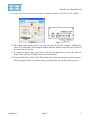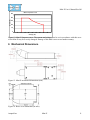
1
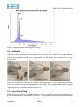
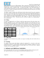
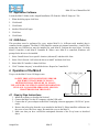
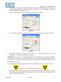
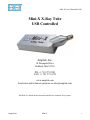
Mini-X User’s Manual Rev B0
Mini-X X-Ray Tube
USB Controlled
Amptek, Inc.
14 Deangelo Drive
Bedford, MA 01730
PH: +1 781 275 2242
FAX: +1 781 275 3470
www.amptek.com
Send sales and technical questions to [email protected]
The Mini-X is based on the Newton Scientific Inc. miniature X-ray source.
Amptek Inc.
Mini-X
i
Mini-X User’s Manual Rev B0
Table of Contents
1
2
3
4
5
6
Precautions........................................................................................................................................ 1
1.1
High Voltage............................................................................................................................. 1
1.2
Radiation................................................................................................................................... 1
1.3
Beryllium Window ................................................................................................................... 2
1.4
Heat and Temperature............................................................................................................... 2
Overview of the Mini-X X-Ray Tube System for Portable XRF..................................................... 2
2.1
Output X-Ray Spectra............................................................................................................... 3
2.2
Collimator ................................................................................................................................. 4
2.3
Brass Safety Plug...................................................................................................................... 4
2.4
Interlock.................................................................................................................................... 5
2.5
Filters ........................................................................................................................................ 6
2.6
Mounting................................................................................................................................... 6
2.7
Cooling ..................................................................................................................................... 6
Software and USB Driver Installation.............................................................................................. 6
3.1
Application Software ................................................................................................................ 7
3.2
USB Driver ............................................................................................................................... 7
Operation of the Mini-X ................................................................................................................... 7
4.1
Step by Step Instructions .......................................................................................................... 7
Specifications.................................................................................................................................. 10
Mechanical Dimensions.................................................................................................................. 11
Amptek Inc.
Mini-X
ii
Mini-X User’s Manual Rev B0
1 Precautions
CAUTION: The Mini-X is only one component of an X-ray instrument. It is the responsibility of the
user, the OEM customer, or experimenter to provide a fail safe metal enclosure to prevent escaping
radiation while using this product. The final product (turn-key system) must comply with local
government regulations to protect personnel from exposure to radiation. Amptek Inc., bears no
responsibility for the incorrect use of this product.
1.1 High Voltage
The Mini-X is designed to generate voltages up to 40 kV. The high voltage system is fully shielded
inside the Mini-X enclosure.
DO NOT ATTEMPT TO ACCESS OR MODIFY THE HIGH VOLTAGE SYSTEM.
DO NOT UNSCREW ANY OF THE SCREWS AT THE NECK OF THE TUBE.
TAMPERING WITH THESE SCREWS WILL VOID WARRANTY.
Caution
This device produces HIGH VOLTAGE when energized.
To be operated only by qualified personnel.
The Mini-X contains a high voltage power supply. High voltage is not exposed, but the Mini-X should
still be grounded as a precaution. It should be mounted to a metal fixture via the provided brackets.
The high voltage power supply has been thoroughly tested and should not ever arc to its own case.
However, if at any time any high voltage arcing or popping is heard, immediately discontinue use.
High voltage arcing has a distinctive sharp cracking sound. Contact sales ([email protected]) if you
suspect that the power supply is arcing.
1.2 Radiation
The Mini-X product is intended to generate X-ray radiation during normal operation. The Mini-X has
been designed to focus radiation in the designated output direction, however radiation in other
directions is possible and should be addressed with shielding and/or monitoring in the final application.
Caution
This device produces X-RAYS when energized.
To be operated only by qualified personnel.
Radiation levels external to the X-ray tube housing with the brass safety plug ON do not exceed 2.5
mrem/h measured 5 cm from the surface of the housing in accordance with Requirements 5.2.2.1.1 and
5.2.2.2.2 of the NBS Handbook for Radiation Safety for X-Ray Diffraction and Fluorescence Analysis
Equipment. For more information please see http://www.fda.gov/cdrh/radhlth/pdf/xdfgehb.pdf.
Amptek Inc.
Mini-X
1
Mini-X User’s Manual Rev B0
1.3 Beryllium Window
When unpacking the Mini-X pay careful attention to the Beryllium (Be) window on the front of the
unit. This is a fragile window which can be damaged by impact. Beryllium (silver/gray and metallic)
and beryllium oxide dust (normally a whitish powder) are harmful if inhaled or ingested.
AVOID ALL CONTACT WITH THIS PART OF THE X-RAY TUBE.
1.4 Heat and Temperature
The ambient temperature surrounding the X-ray tube must not exceed 50 oC. Improper cooling is the
single highest cause of X-ray tube failures and is not covered under the Mini-X Warranty. It is the
user’s responsibility to provide an adequate cooling system for the Mini-X.
2 Overview of the Mini-X X-Ray Tube System for Portable XRF
Important – Read the precautions in Section 1 of this manual before operating this equipment.
Mini-X is the first of its kind; a self-contained, packaged, miniature X-ray tube system, which includes
the X-ray tube, the power supply, the control electronics and the USB communication to the computer.
It is designed to replace radioisotopes in X-ray fluorescence analysis applications.
Mini-X has been designed to simplify the XRF process by providing a grounded anode, variable
current and voltage controlled via USB and ease of operation. It features a 40 kV/100 µA power
supply, a tungsten (W) or silver (Ag) transmission target, and a beryllium end window. A collimator
and various filters are also provided. It is designed for continuous operation in industrial environments.
To further simplify the use of Mini-X an AC adaptor is provided to supply the 9 VDC needed to power
the system. The only connections needed to operate the tube are a USB cable and AC adaptor. A
flashing red LED and a beeper warns the user when x-rays are present.
CAUTION: DO NOT SET THE VOLTAGE OVER 40 kV.
THIS WILL DAMAGE THE UNIT AND VOID WARRANTY.
Amptek Inc.
Mini-X
2
Mini-X User’s Manual Rev B0
Figure 1. Complete XRF System. The Mini-X together with the XR-100CR X-ray detector and the
PX4 Digital Pulse Processor, MCA, and Power Supply.
2.1 Output X-Ray Spectra
Figure 2. Output Spectrum with Silver (Ag) target.
Amptek Inc.
Mini-X
3
Mini-X User’s Manual Rev B0
Figure 3. Output Spectrum with Tungsten (W) target.
2.2 Collimator
The Mini-X is provided with a collimator to facilitate its use in XRF applications. It consists of a brass
collimator with an aluminum (Al) insert and a cover that screws into the Mini-X. Insert the collimator
into the cover and then carefully screw the assembly onto the Mini-X. The collimator has a 2 mm
diameter hole.
Figure 4. Left photo shows the Mini-X collimator, safety plug, and cover. The middle photo shows the
safety plug installed in the cover and attached to the Mini-X. This configuration meets the radiation
requirements discussed in Section 1.2. The Mini-X ships from the factory in this configuration. The
right photo shows the collimator installed in the cover.
2.3 Brass Safety Plug
When the brass safety plug is installed in the cover (figure 4, middle) and screwed onto the Mini-X it
meets the radiation safety requirements of Section 1.2. For personal protection always install the safety
Amptek Inc.
Mini-X
4
Mini-X User’s Manual Rev B0
plug into the cover and attach to the Mini-X when not in use. The Mini-X ships from the factory in this
configuration.
2.4 Interlock
The Mini-X has a hardware interlock in order to prevent accidental exposure. This interlock must be
shorted (enabled) in order for the Mini-X to produce X-rays. The left figure below shows the interlock
disabled. The Mini-X will not produce X-rays in this configuration. The right figure shows the
interlock enabled. The Mini-X will produce X-rays in this configuration. Always store the Mini-X with
the interlock disabled when not in use.
Figure 5. Showing the interlock disabled (left) and enabled (right).
One of the primary purposes of the interlock is so that the user can interface to external safety
mechanisms. This is most commonly implemented as a shutter or cover that, when opened, disables the
interlock and stops the generation of X-rays. When the tube is producing X-rays and the interlock is
disabled, the tube will go into a reset mode. It is therefore necessary to restart the tube through
software. Re-enabling the interlock after disabling it will not resume the production of X-rays.
The figure below is a block diagram of the Mini-X power and control interface, illustrating the use of
the “Interlock” connector. This connector has two functions: it permits the user to implement a safety
interlock, which turns off the X-ray tube when a switch is opened, and it permits the user to implement
an external indicator to show when the tube is in use.
J1
J3
PWR
1
PWR
9VDC
Interlock
Switch
PWR
IN
Control &
Monitor
PWR
IN
2
HVPS
3
V
Q1
X-ray
Tube
USB
Indicator
4
Indicators
Typical customersupplied interface
J2
~1 Hz
Figure 6. Power and control interface.
As shown in the figure, power is supplied to the high voltage power supply (HVPS) via a connection
between pins 1 and 2 of the interlock connector. If the connection between these pins is interrupted,
there is no power to the HVPS and so the tube turns off. In addition, this latches a bit in the monitor
Amptek Inc.
Mini-X
5
Mini-X User’s Manual Rev B0
circuit, which must be reset via a USB command. When a connection is restored between pins 1 and 2,
although power is restored to the HVPS, the unit is not turned on until this command is received. The
voltage at pins 1 and 2 is typically 9VDC. As shown in the figure, a user could connect this to a
switch, typically located on the cover of the enclosure housing the X-ray target. If a user accidentally
opens the cover without first turning off the tube, this will automatically turn off the power, preventing
accidental radiation exposure.
The Mini-X contains a speaker and an LED, both of which indicate that the X-ray tube is turned on.
The LED is visible on the back side of the Mini-X package, but in some applications the Mini-X is
inside an enclosure. Pins 3 and 4 can be used to drive an external indicator, such as the LED sketched
above. The user must provide the circuit interfacing to pins 3 and 4. Q1 is an N-channel enhancement
mode MOSFET, part number ZXM61N02FTA. Key ratings are VDSS=20V (absolute max) and
ID=1.7A (absolute max, 25oC). The gate of the FET is driven by a square wave at approximately 1
Hz, 10% duty cycle.
2.5 Filters
The Mini-X is shipped with a set of filters to modify the output spectrum of the tube to better suite a
particular application. The use of any filter will reduce the flux, so the current may have to be
increased to obtain an appropriate flux. Install the filter at the Mini-X screw base. Then screw on the
cover with the collimator. Make sure that the cover screws all the way down, otherwise radiation will
leak through the gap. All filter thicknesses will fit except for the 40 mil Al. This filter must be
installed on the outside output aperture of the collimator and held in place with the black cap provided.
Material
Thickness
μm/mils
#
Included
Al
1016 / 40
5
Al
254 / 10
5
Cu
25.4 / 1
3
Mo
25.4 / 1
2
Ag
25.4 / 1
1
W
25.4 / 1
1
2.6 Mounting
The Mini-X can be fastened to any surface by using the mounting holes and brackets that are
provided.
2.7 Cooling
The Mini-X requires proper and adequate cooling for maximum life. As such, it is the user’s
responsibility to provide a cooling design, such that the ambient temperature around the X-ray tube
does not exceed 50 oC. Improper cooling is the single highest cause of X-ray tube failures. Improper
cooling is not covered under the warranty.
3 Software and USB Driver Installation
Do not plug in the Mini-X until you have first installed the Application Software. This process will
also copy the USB drivers to your computer so that USB driver installation is easier.
Amptek Inc.
Mini-X
6
Mini-X User’s Manual Rev B0
3.1 Application Software
Locate the Mini-X folder on the Amptek Installation CD. Run the “Mini-X Setup.exe” file.
1. When the dialog opens click Next.
2. Click Install.
3. Click Finish.
4. Another Wizard will open.
5. Click Next.
6. Click Finish.
3.2 USB Driver
This procedure must be performed for every unique Mini-X (i.e. different serial number) that is
connected to the computer. The Mini-X USB interface contains two internal controllers, A and B. This
means that two USB drivers must be installed for each Mini-X. Perform the steps below for both
Mini-X Controller A and Mini-X Controller B. When a new Mini-X is connected, Windows will
prompt for the drivers to be installed.
1. Select “Install from a list or specific location (Advanced)” and then click Next.
2. Select “Don’t Search. I will select the driver to install” and then click Next.
3. Select Mini-X Controller A then click Next.
4. Click "Continue Anyway" to install the drivers. Repeat for Controller B.
4 Operation of the Mini-X
X-rays exit the Mini-X in an 120 degree cone.
SAFETY PRECAUTIONS MUST BE USED FOR
EQUIPMENT THAT PRODUCE X-RAYS.
MINIMIZE HUMAN EXPOSURE TO X-RAYS.
USE A GEIGER COUNTER TO MONITOR RADIATION.
STOP: ONLY QUALIFIED PERSONNEL SHOULD
PROCEED BEYOND THIS POINT.
Figure 7. Output X-Ray cone.
4.1 Step by Step Instructions
1. Install the software as described in Section 3.
2. Connect the Mini-X to the PC computer with the USB cable.
3. Connect the AC power adapter to the Mini-X and plug it into an appropriate 110/220 AC power
outlet.
4. Remove the safety plug from the cover attached to the Mini-X. Either install the collimator into
the cover or leave the cover empty. Re-attach the cover to the Mini-X.
5. Make sure that you have verified the anticipated direction of the X-ray beam as described
above.
Amptek Inc.
Mini-X
7
Mini-X User’s Manual Rev B0
6. The Mini-X has a hardware interlock in order to prevent accidental exposure. This interlock
must be shorted (enabled) in order for the Mini-X to produce X-rays. Install the interlock plug
to enable the Mini-X to produce X-rays.
7. Open the Amptek Mini-X Controller Software. It will appear as below.
Figure 8.
8. Click the Start Amptek Mini-X button. The software will display the serial number of the unit.
Figure 9.
9. The software defaults to a setting of 15 kV and 15 μA. To change the values click into the
appropriate text box and type in the desired number.
IMPORTANT: Do not enter a voltage higher than 40 kV. In addition, the total power of the MiniX is governed by the Isopower curve. Do not enter a current that exceeds the indicated value for
that voltage. If a requested current is too high, the software will automatically adjust it to the
maximum allowed value.
10. Click the HV ON button to turn on the tube. The software will ask you to confirm. Click Yes.
THE MINI-X IS NOW PRODUCING X-RAYS
11. The Mini-X will start to beep and the red LED on the end panel of the unit will flash. In
addition the yellow and black “Radiation Symbol” will blink in the Mini-X Software and the
words “X-Ray ON” will appear.
Amptek Inc.
Mini-X
8
Mini-X User’s Manual Rev B0
For your safety and for the safety of others, the Beeper should be left ON AT ALL TIMES.
Figure 10.
Figure 11.
12. The Voltage and Current monitors now show the actual X-ray tube condition. Although the
values for Voltage and Current might be slightly different from the requested values, these are
the actual values of the tube.
13. To change the high voltage and current, click into the appropriate text box and enter the
number. Then click the Set High Voltage and Current button.
14. To turn off the Mini-X click the HV OFF button, then click the Exit button to exit the software.
Always unplug the Mini-X, install the safety plug, and disable the interlock when not in use.
Amptek Inc.
Mini-X
9
Mini-X User’s Manual Rev B0
5 Specifications
Target Material
Silver (Ag) or Tungsten (W)
Target Thickness
1.5 µm
Tube voltage
10 to 40 kV
Tube current
5 µA min. / 200 µA max
See Isopower curve below
Approximate Dose Rate
800 µGy/s at 40 kV, 50 µA (W target) at 30 cm
Approximate Flux
106 cps at 40 cm through 1 mm diameter collimator (40 keV, 100 µA)
Continuous Output Power
4 W max at 100% duty cycle
See Isopower curve
Window Material
Beryllium (Be); window at ground
Window Thickness
500 µm
Focal Spot Size
Approximately 2 mm
Cooling
Air Cooled
High Voltage Stability
<0.03% RSD
Leakage Radiation
<100 nSv/h
Power Consumption
8.5 W at 40 kV and 100 µA, 9 VDC input power
Input Voltage
9 VDC (AC adapter included), connector
Control
USB, mini-USB connector (cable included)
Settling Time
Typical <1 second
Weight
360 grams
Humidity
30 to 90% non-condensing
Operating Temperature Range -10 °C to 50 °C
Storage Temperature Range
-25 °C to 60 °C
1) External Hardware Interlock
Safety Controls and Indicators 2) Flashing LED
3) Beeper
Warranty
Amptek Inc.
One year or 2000 hours, whichever comes first
Mini-X
10
Mini-X User’s Manual Rev B0
Mini-X Isopow er Curve
250
Current (uA)
200
150
100
50
0
0
5
10
15
20
25
30
35
40
45
50
Voltage (kV)
Figure 12. Mini-X Isopower curve. The current and voltage must be set in accordance with this curve
or the Mini-X may be severely damaged. Damage of this kind is not covered under warranty.
6 Mechanical Dimensions
Figure 13. Mini-X mechanical dimensions (mm).
Figure 14. Brass cover dimensions (in mils).
Amptek Inc.
Mini-X
11