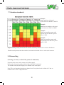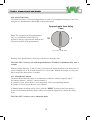
1
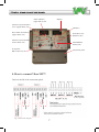
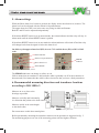
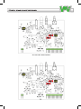
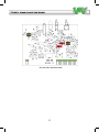
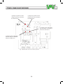
VIBER M2™
Machine Protector
1 or 2 Channels
User manual
Version 1.7
Accelerometer Channels CH-A-B ver. 1.3-1.4
Index
1.
Important information4
2.
Introduction5
3. General description6
4. How to connect Viber M2™
7
5. Alarm settings9
6.
Recommended measuring directions and
transducer locations according to ISO 10816-3 9
7.
Vibration standards10
8.
Dismantling10
9.
Description of Settings11
9.1.
Accelerometer Setup
11
9.2.
High Pass Filter
11
9.3.
Low Pass Filter
11
9.4.
Signal Range
11
9.5.
Output Signal
12
9.6.
Alarm Function
12
9.7.
Relay Coil
12
9.8.
Relay 1 and Relay 2
12
9.9.
Error Indication
12
9.10. Alarm Time Delay
13
9.11. Alarm Reset Function
13
3
1. Important information
Safety precautions
Vibration measurement involves measurement on rotating machines. Keep a safe distance to
rotating parts and secure transducers and transducer cables from rotating parts. Always follow
internal, local and national security regulations! When working with weights on the rotor,
always secure the start switch with a locker and also use the emergency switch for double
safety. This is especially important when the machine is remote controlled.
VMI takes no responsibility for any accidents on people and machines.
VMI and our authorized dealers will take no responsibility for damages on machines and plants
as the result of the use of Viber M2™ measurements.
Even though great efforts are made to make the information in this manual free from errors and
to make the information complete for the user, there could be items we have missed, because of
the large amount of information. As a result of this, we might change and correct these items in
later issues without further notice. Also changes in the Viber M2™ equipment may take place
that affect the accuracy of the information.
VMI AB warrants the products to be free from defects in material and workmanship under
normal use and service within two years from the date of purchase and which from our
examination shall disclose to our reasonable satisfaction to be defective.
Warranty claimed products shall be returned prepaid to VMI AB for service. We
reserve the right to repair or to replace defective products.
Always try to explain the nature of any service problem, in the ‘Repair/Calibration order’,
available on the VMI web page www.vmiab.com, preferably by email. First check all natural
problems like broken cables etc. When returning the product, be sure to indicate that the
purpose is to make repair and indicate the original date of shipment to you if possible.
Warranty is voided if other changes then recommended by VMI are made to the
product.
4
2. Introduction
Viber M2™ is a versatile, reliable and easy to use machine protector unit. M2 will give an alarm
or stop the machine if failure is imminent. The M2 sends constantly machine vibration
information as well as transducer and cable condition to the PLC.
Viber M2™ has two (or option with one) monitoring channels available for accelerometers.
Each channel has:
• Three measuring ranges.
• Two independent alarm levels with manual or auto reset
• Two frequency ranges
• Current output proportional to the vibration level 4- 20 mA, suitable for connection to a PLC
• Monitoring of transducer and cable failure
• Analysis signal on BNC and terminal output
Common for both channels:
• Two independent change over relays
• Two independent time delays of relay function
• One changeover relay for transducer or cable failure
5
3. General description
The transducer signal is compensated in the input amplifier to correct signal level and selected
frequency range. This signal is available at the front panel BNC connector and on terminals for
further analysis.
When accelerometer or velocity transducers are used the analysis, alarm and mA signals are
always measured in velocity. This signal can be amplified in 3 selectable ranges 0-10, 0- 20 and
0-100 mm/s. Other ranges are optional upon order of the product.
The instrument measures the RMS value of the signal within the selected frequency range.
When the preset alarm levels are reached a LED lamp is lit. If the levels stays higher during the
selected delay time (0- 30 sek) the relay is changing. The M2 has Manual or automatic resetting
of the alarm status.
The signal level is converted to a corresponding current output between 4-20mA.This signal is
available on terminals for connection to other instruments or data logger. The current output is
disabled in case of transducer or cable failure.
Enclosure: Sealed (IP65), PVC box with transparent lid for overview of vibration and/or
temperature levels, alarm settings and alarm status.
Enclosure dimensions: Width 170mm, height 160mm, depth 130mm.
The current output is 4-20 mA on pc-board. Max. load not more than 600 ohm or 12V. 20 mA
refers to 100% of selected measuring range.
The time delay of relay activation is adjustable between 0 and 30 sec.
Power supply: Standard is 100-240VAC. Optional 24VDC.
Input sensitivity: Standard 100mV/g. The positive input terminal supplies a 4 mA constant
current at max. 20V to the built in transducer amplifier.
Frequency range: 10 - 4000 Hz is preset. The lowest frequency range can be changed to 2 Hz
and the low-pass filter can be disabled, on the pc-board.
Analysis output: 100 mV/g between 2 Hz-15000 Hz.Min load 10 k Ω.
If only one channel is used, then the second channel input must be terminated with a resistor
of about 4700 ohms. No channels should be left open.
6
Alarm indicator
(upper alarm, ch1)
Alarm level potentiometer
screw (upper alarm, ch1)
Display
Channel 2
Show alarm level button
(upper alarm, ch1)
Transducer error
indicator (ch2)
Alarm level potentiometer
(lower alarm, ch1)
Alarm RESET
button (ch2)
Front panel
BNC connector, ch1
Connection panel
Fig.1 Front panel
4. How to connect Viber M2™
Unscrew the lid of the connection panel.
(or 24v optional)
Fig. 2 Connection Diagram
7
The Viber M2™ casing is IP65 protection classed, this can be degraded if improper cable sealings are used.
The Accelerometer is connected between IN+ and IN- (signal conductor to IN+ and common
to IN-), the cable screen is connected to the screen input. Note that the accelerometer is polarity
sensitive and some transducers can be destroyed by reversed polarity.
Look at the transducer data sheet for correct polarity.
In an industrial environment it is normal possible to use up to 200 meter of cable between the
transducer and the M2.
The AC OUT terminal and the BNC connector output are buffered signal with the same
sensitivity as the connected transducer. The buffered output can normally absorb the constant
current source coming from connected analyzer without influencing the signal.
The signal is accessible between terminals GND and AC OUT.
The mA + output gives a signal between 4- 20 mA proportional to the selected full scale range.
Maximum load of mA + output is 600 Ω.
The signal is accessible between terminals GND and mA +.
Relay 1 acts on alarm level H1 (see fig 1. Front panel)
Relay 2 acts on alarm level H2.
Relay 3 acts on transducer and cable failure.
MAINS
As standard the M2 is delivered with a switched power supply that accepts 100- 240 VAC.
If theViber M2™ is delivered for + 24 VDC the same terminals are used as for 240 VAC. The
M2 is polarity protected and the polarity on the terminals can be changed.
8
5. Alarm settings
While the Show alarm level switch is pressed, the display shows the alarm level, in mm/s. The
alarm level can be adjusted with the Alarm level potentiometer.
The upper alarm level H2 is set in the same way using its dedicated buttons.
Both H1 and H2 can be adjusted independently.
If the Alarm RESET button is set in manual mode, the Alarm indicator and the relay will stay in
alarm mode until the Alarm RESET button is pushed.
If the Alarm RESET button is set in auto mode the Alarm indicator will switch off and the relay
will change back when the signal is below the alarm level.
On delivery, the upper alarm level (H2) is set to 71% and the lower (H1) to 28% of full
scale.
Alarm indicator
Alarm level potentiometer
ERROR
indicator
Show alarm level
Alarm RESET
Fig. 3 Lower alarm level (H1) buttons
Fig. 4 ERROR indicator
The ERROR indicator can change to yellow or red.
Yellow means that no transducer is detected (the cable is probably cut off or the transducer is
disconnected). Red means that the cable is short circuited or that you have a faulty transducer.
6. Recommended measuring directions and transducer locations
according to ISO 10816-3
Measure on or as close to the
bearings as possible.
Measure vertically and horizontally
in a direction that points to the shaft centre.
Measure axially in the same height
as the shaft centre.
Fig. 5 Measuring directions
Do not measure on thin sheet metal plates.
Before permanently mounting the transducer measure on the positions as suggested in fig. 5.
For monitoring purposes use one of the measuring points with the highest vibration.
9
7. Vibration standards
Group 1:
Large machines with rated
power between 300kW to 50 MW
Group 2:
Medium size machines with rated
power between 15kW to 300kW
Group 3:
Multivane impeller pumps with
seperate drivers that have power
above 15kW
Group 4:
Multivane impeller pumps with
integrated drivers that have power
above 15kW
Rigid mounting usually means that the machine is directly mounted on a concrete foundation.
Flexible usually means that the machine is mounted on flexible feet or a weak steel structure.
8. Dismantling
(Warning, warranty is voided if the product is dismantled)
Unscrew the 4 screws at the corners of the front panel.
Pull out the electronics gently with the help of the BNC connectors.
The channel cards and the displays are attached to the front panel.
Note! The card mounting brackets on channel card 2 are placed at the “solder side” and on
channel card 1 at the “component side”.
10
9. Description of settings
9.1. Accelerometer Setup
The Viber M2™ accelerometer input has a 4 mA constant current generator at maximum
20VDC, the input sensitivity is 100mV/g. An input amplifier that converts acceleration to
velocity.
The input ‘IN+’ on the mother board is the signal input from the accelerometer, and also the
output for the 4mA DC current, used to power the internal amplifier in the accelerometer.
The input ‘IN-‘ is the return signal input from the accelerometer and is also GND. The input
‘SCREEN’ is internally connected to the input ‘GND’, and can be used for the cable shield.
Note that the cable shield should be connected in one end only.
9.2. High Pass Filter
With the switch S2 in position LEFT, minimum frequency range is 10 Hz, in position RIGHT
2 Hz.
Unless otherwise is specified in the order, the Viber M2™ is factory set with S2 in position
LEFT, 10 Hz.
9.3.Low Pass Filter
With the switch S1 in position LEFT maximum frequency range is 4 kHz.With the switch S1 in
position RIGHT the low-pass filter is disabled.
Unless otherwise is specified in the order, the Viber M2™ is factory set with S1 in position
LEFT, up to 4 kHz.
The ‘acceleration’ signal is available at the AC output (BNC), and at the screw terminal ‘AC’.
The signal sensitivity is the same as the connected transducer, approximately 100mV/g.
9.4. Signal Range
The ‘velocity’ signal is amplified with a range amplifier in one of 3 preset ranges: 10, 20 or 100
mm/s, selectable with the DIP switches J3A and J3B
J3A settings:
1 ON= 0- 10 mm/s
2 ON= 0- 20 mm/s
3 ON= 0- 100 mm/s
Only one switch on J3Ashall be ON
at the same time
J3BSettings:
1 ON= 0- 100 mm/s
2 ON= 0- 10 and 0- 20 mm/s
3 ON= 0- 10 and 0- 100 mm/s
For 10 mm/s both 2 and 3 should be ON.
For 20 mm/s only 2 should be ON.
For 100 mm/s both 1 and 3 should be ON.
See pictures on pages 14 and 15.
The Viber M2™ is factory set with J3A and J3B in the range 0-10 mm/s.
11
9.5. Output Signal
A mean value of the signal (true RMS) is then created. This ‘RMS’ signal is available as a DC
current, between 4 and 20 mA. If a transducer error (cable broken or shorted) occurs, the current
is set to 0 mA. Maximum output voltage is 12 Volt at maximum 600 ohm load.
This signal is suitable for an external panel instrument or a process logging system.
9.6. Alarm Function
The ‘RMS’ signal is also input to two independent sets of alarm comparators, where (usually)
one is set to a lower level and serves as a first warning, and the other to a higher level, to give a
critical warning.
If the RMS level is higher than the alarm value set by any of the independent potentiometers,
the comparator will turn on the front indicator LED and at the same time a preset delay circuit is
triggered. If the RMS level is above the alarm level during the whole time delay, the alarm relay
is activated.
9.7. Relay Coil
With the jumper S1 and S2 on the motherboard, it is possible to select if the relay coil shall be
energized above or below the alarm limit.
With the jumper in position B the coil is energized if the vibration is below the alarm limit. This
position also means that a power failure to the Viber M2™ gives a change in the relay output.
The Viber M2™ is factory set with the switches S1 and S2 on the motherboard in position
A (the coil is energized if the vibration is above the alarm limit).
9.8. Relay 1 and Relay 2
Relay 1 will change at the H1 level and Relay 2 will change at the H2 level.
Below the alarm level (when relay is not activated), the screw terminals marked with 2 and 3
are short-circuited. When the relay is activated, the terminals 1 and 3 are short-circuited.
The channel cards share the relays.
A relay is activated when the vibration level of any of the channels is higher than the alarm
level.
The relay breaking capacity is 250 VAC 5 Amp.
9.9. Error Indication
The Viber M2™ detects two types of transducer errors; Shorted or Broken Cable, by measuring
the transducers bias voltage.
A cable error is reported via the ‘ERROR’ LED, on the front panel of the instrument. A broken
cable is indicated with a yellow light, while a short-circuit is indicated with a red light. Also,
Relay number 3 is activated, and the current that normally is 4 - 20 mA is set to 0.
12
9.10. Alarm Time Delay
The alarm time delay is selected independently for each set of comparators, between 3 and 30 s,
using the two potentiometers P1 and P2 on the mother board.
Approximate time delay
Approximate time delay
3 sec.
setting 8 sec.
Note: The orientation of the potentiometers
may vary on different boards. The Top
position in this fig. represents the furthest anticlockwise position of the potentiometer.
9030
sec.
7
30
sec.
60
15
Fig. 6 Settings on P1 & P2
Rotation of the potentiometers clockwise will increase the delay time.
The Viber M2™ is factory set with the potentiometers P1 and P2 to minimum delay time 3
seconds.
With the jumper S4 (relay 1) and S5 (relay 2) closed on the motherboard, the time delay interval
will be changed to 0 to 30 seconds instead of 3 to 30 seconds. Without the jumper it is not possible to set the time delay below 3 seconds.
9.11. Alarm Reset Function
The Alarm Reset function can be set to Automatic or Manual, with the straps S6 and S7.
S6 controls channel 1, while S7 controls channel 2.
If a jumper is open, Alarm Reset is set to Automatic for the corresponding channel.
If a jumper is closed, Alarm Reset is set to Manual.
In Manual mode, the alarm will be active, until the ‘RESET’ button (on the front panel) is
pressed. In Automatic mode the alarm will be reset when the signal level is below the alarm
level.
The Viber M2™ is factory set to Automatic mode.
13
14
15
A jumper in position A will
energize the relay coil above
the alarm limit.
A jumper in position A will
energize the relay coil above
the alarm limit.
A jumper on S5 will change
the time delay on channel 2
between 0 and 30 sec.
A jumper on S4 will change
the time delay on channel 1
between 0 and 30 sec.
Fig. 7 Motherboard, relay coil, 54 and 55 position
16
Fig. 8 Channel Card, S1, S2, S6 and S7 position
17
18
19
VMI International AB
Gottorpsgatan 5 • SE-582 73 Linköping
Phone +46 (0)13-474 37 00
E-mail: [email protected] • www.vmiab.com