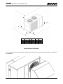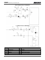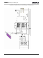
1
MUI011081520-00
Catalogo/Catalogue/Katalog/Brochure
HWAR 06 ÷41
Serie/Series/Serie/Série
-
Sostituisce/Superseedes
Ersetzt/Remplace
10.08
Emissione/Edition/AusgabeIssue
INSTALLATION AND OPERATION MANUAL
A I R
C O N D I T I O N I N G
R407c
HIGH EFFICIENCY AIR TO WATER HEAT PUMPS
SCROLL COMPRESSORS
WITH DOMESTIC HOT WATER PRODUCTION
HWAR High efficiency air to water heat pumps
MUI0111081520-00
2
HWAR High efficiency air to water heat pumps
INDEX
Declaration of conformity
page3
Aim and contents of this manual
page 6
How to keep this manual
page 6
Graphic symbols
page 6
Safety laws
page 7
General safety guidelines
page 7
Workers’ health and safety
page 8
Protective equipment
page 8
Safety signs
page 8
Unit description
page 9
Operation limits
page 10
Corrections tables
page 11
Sound Data
page 11
Safety Device Setting
page 12
Electric data
page 12
Inspection
page 12
Lifting and handling
page 12
Location and minimum technical clearances
page 13
Installation of the hoods
page 14
Hydraulic connections
page 15
Basic version hydraulic components
page 16
Domestic hot water hydraulic connections
page 17
Electrical connections
page 18
Start up
page 18
Controls during operation
page 19
Maintenance and periodic checks
page 19
Refrigerant circuit repair
page 20
Environment protection
page 20
Unit out of service
page 20
Fault finding
page 20
Dimensions
page 22
MUI0111081520-00
3
HWAR High efficiency air to water heat pumps
The HWAR manual, contains any information that is needed for a correct use of the equipment while safeguarding operator safety,
according to what indicated from “Council Directive” 98/37/CE and following changes.
AIM AND CONTENTS OF THIS MANUAL
This manual provides basic information on the installation, operation and maintenance off the HWAR unit. It is addressed to machine
operators and it enables them to use the equipment efficiently, even if they do not have any previous specific knowledge of it.
This manual describes the characteristics of the equipment at the time it is being put on the market; therefore it may not capture later
technological improvements introduced by MAXA as part of its constant endeavour to enhance the performance, ergonomics, safety
and functionality of its products.
HOW TO KEEP THIS MANUAL
The manual must be always with the unit it refers to. It must be stored in a safe place, away from the dust and moisture. It must be
accessible to all users who shall consult it any time they are in doubt on how to operate the equipment.
MAXA reserves the right to modify its products and related manuals without necessarily updating previous versions of the reference
material. The customer shall store any updated copy of the manual or parts of it delivered by the manufacturer as an attachment to
this manual.
MAXA is available to give any detailed information about this manual and to give information regarding the use and the maintenance
of its own units.
GRAPHIC SYMBLS
Indicates operations that can be dangerous for people and/or disrupts the correct operation of the
equipment..
Indicates prohibited operations.
Indicates important information that the operator must follow in order to guarantee the correct operation
of the equipment in complete safety
MUI0111081520-00
4
HWAR High efficiency air to water heat pumps
SAFETY LAWS
MAXA equipment and their component parts have been designed in compliance with the harmonised EC norms in force and other
European and national norms as required by the Council Directive (98/37 and later amendments).
The equipment i salso compliant with:
• Norms EN 292-1 e 292-2
• Norma EN 294
• Norms EN 378-1, 378-2, 378-3 e 378-4
• Norma EN 418
• Norma EN 953
• Norma EN 1050
• Norma EN 60204-1
• Norma EN 61000-6-2
• Norma EN 61000-6-4
• Community Directives 98/37/CE, 97/23/CE, 93/68/CEE, 89/336/CEE 73/23/CEE
GENERAL SAFETY GUIDELINES
Before beginning to operate on HWAR units every user must be perfectly knowledgeable about the functions of the equipment and
its controls and must have read and understood the information container in this manual.
It’s strictly forbidden to remove and/or camper with any safety device.
Any routine or not-routine maintenance operation shall be carried out when the equipment has been shut
down, disconnected from electric and pneumatic power source and after its pneumatic system has been
discharged.
Do not put your hands or insert screwdrivers, spanners or other tools into moving parts of the equipment.
The equipment supervisor and the maintenance man must receive training suitable for the performance of
their tasks in safety
Operators must know how to use personal protective devices and must know the accident-prevention
guidelines contained in national and international laws and norms.
MUI0111081520-00
5
HWAR High efficiency air to water heat pumps
WORKERS’ HEALTH AND SAFETY
The European Community has adopted a number of directives on workplace health and safety, which include directives 89/391/CEE,
89/686/CEE, 89/655/CEE, 86/188/CEE and 77/576/CEE. Every employer shall implement such provisions and ensure that workers
respect them:
Do not tamper with or replace parts of the equipment without the specific consent of the manufacturer.
The manufacturer shall have no responsibility whatsoever in case of unauthorised operations.
Using components, expendable materials or spare parts that do not correspond to those recommended
by the manufacturer and/or listed in this manual may be dangerous for the operators and/or damage the
equipment
The operator’s workplace must be kept clean, tidy and free from objects that may camper free
movements. Appropriate lighting of the work place shall be provided so as to allow the operator to carry
out the required operations safely. Poor or too strong lighting can cause risks.
Ensure that work places are always adequately ventilated and that aspirators are working, in good
condition and in compliance with the requirements of the laws in force..
PERSONAL PROTECTIVE EQUIPMENT
When operating and maintaining the HWAR unit, use the following personal protective equipment.
Protective clothing: Maintenance men and operators must wear protective clothing that complies with the
basic safety requirements currently in force. In case of slippery floors users must wear safety shoes with
non-slip soles.
Gloves: During maintenance or cleaning operation protection gloves must be used
Mask and googles: Respiratory protection (mask) and eye protection (goggles) should be
used during cleaning and maintenance operations.
SAFETY SIGNS
The equipment features the following safety signs, which must be complied with:
General hazard
Electric shock hazard
MUI0111081520-00
6
HWAR High efficiency air to water heat pumps
TECHNICAL CHARACTERISTICS
The high efficiency HWAR heat pump series have been especially designed for application with radiant floor heating systems or in
those applications where it is necessary to have the highest maximum efficiency in heating mode. The units have been optimized for
heating mode, they are able to produce water up to 60°C and they can operate down to -15°C ambient temperature. All models are
supplied standard with reverse cycle valve for cold water production.
Frame
All HWAR units are made from hot-galvanised thick sheet metal, painted with polyurethane powder enamel at 180°C to ensure the
best resistance against the atmospheric agents. The frame is self-supporting with removable panels. All screws and rivets for
outdoor installations are in stainless steel. The colour of the units is RAL 7035.
Refrigerant circuit
The refrigerant gas used in these units is R407C. The refrigerant circuit is made by using international primary brands components
and according to ISO 97/23 concerning welding procedures. The refrigerant circuit includes:
sight glass, filter drier, double thermal expansion valves (one for cooling mode, one for heating mode) with external equalizer, 4 way
reverse cycle valve, one way valves, liquid receiver, Schrader valves for maintenance and control, pressure safety device (according
to PED regulation). Models starting from 10T are also supplied with an AISI316 stainless steel heat exchanger used as economizer
and additional expansion valve for refrigerant vapour injection.
Compressors
The compressors used are high performance scroll type, supplied with a special scroll design who enhance the efficiency of the
refrigerant cycle at low ambient conditions. Units starting from model 10T, are also supplied with an additional heat exchanger used
as economizer and a vapour injection system, used to enlarge the working range. The compressors are all supplied with crankcase
heater and thermal overload protection by a klixon embedded in the motor winding. They are mounted in a separate chamber in
order to be separated from the air stream. The crankcase heater is always powered when the compressor is in stand-by. The
inspection is possible through the frontal panel of the unit that allow the maintenance of the compressors even if the unit is working.
Source heat exchanger
The source heat exchangers are made of copper pipes and aluminium fins. The diameter of the copper pipes is 3/8” and the
thickness of the aluminium fins is 0,1 mm. The tubes are mechanically expanded into the aluminium fins to improve the heat
exchange factor. The geometry of these condensers guarantee a low air side pressure drop and then the use of low rotation (and low
noise emission) fans. The source heat exchangers can be protected by a metallic filter to be installed on request.
Fans
The fans are axial type with aluminium aerofoil blades. They are statically and dynamically balanced and supplied complete of the
safety fan guard according to EN 60335. They are mounted on the unit frame by interposition of rubber vibration dampers. The
electric motors are all at 6 poles (about 900 rpm). The motors are directly driven with an integrated thermal overload protection. The
protection class of the motors is IP 54.
User heat exchangers
The user heat exchangers are made of AISI 316 stainless steel braze-welded plates type. The use of these kind of heat exchangers
allows a massive reduction of the refrigerant charge of the unit compared to the traditional shell-in-tube evaporators and also a
reduction of the overall dimensions of the unit. The user heat exchangers are factory insulated with flexible close cell material and
can be equipped with antifreeze heater (optional). Each heat exchanger is provided with a temperature sensor as antifreeze
protection.
Electric box
The electric box is made according to electromagnetic compatibility norms CEE 73/23 and 89/336. The accessibility to the board is
possible after removing the front panel of the unit. The protection degree is IP55. In all HWAR units are installed, standard, the
compressors sequence relay who disable the operation of the compressor in case the power supply phase sequence is not the
correct one (scroll compressors in fact, can be damaged if they rotate reverse wise). The following components are also standard
installed: main switch, magnetic-thermal switches (as a protection of pumps and fans), compressors fuses, control circuit automatic
breakers, compressor contactors, fan contactors, pump contactors. The terminal board is supplied with voltage free contacts for
remote ON-OFF , winter/summer change over and general alarm.
Microprocessors
All HWAR units are supplied standard with microprocessor controls. The microprocessor controls the following functions: regulation
of the water temperature, antifreeze protection, compressor timing, compressor automatic starting sequence, alarm reset. The
control panel is supplied with display showing all operational icons. The microprocessor is set for automatic defrost (in case of
operation in severe ambient conditions) and for summer/winter/domestic hot water change over (SA versions only). Upon request
any microprocessor can be connected to a BMS system for the remote control and management. The technical department is
available to study, together with the customer, different solutions using MODBUS; LONWORKS; BACNET or TREND protocols.
MUI0111081520-00
7
HWAR High efficiency air to water heat pumps
Control and protection devices
All units are supplied with the following control and protection devices: Return user water temperature sensor, antifreeze protection
sensor installed on the user outlet water temperature, return and supply domestic hot water sensors (SA versions only), high
pressure switch with manual reset, low pressure switch with automatic reset, high pressure safety valve, compressor thermal
overload protection, fans thermal overload protection, pressure transducer (used to optimize the defrost cycle and the fan speed
depending on the ambient conditions), flow switch.
OTHER VERSIONS
HWAR/SA
UNIT WITH DOMESTIC HOT WATER PRODUCTION
This version is suitable to produce domestic hot water: the unit is supplied with an additional heat exchanger used as condenser for
the domestic hot water that, is independently from the operation mode of the unit. The activation of the additional heat exchanger is
done automatically by the microprocessor control when the domestic hot water temperature measured by the sensor is lower than
the required set point. This unit allow the production of cold and hot water at the same time independently. This version is supplied
with return/supplied domestic hot water sensors and advanced control panel with specific software able to manage the operation
priorities.
HWAR / A1
HIGH EFFICIENCY HEAT PUMP WITH INTEGRATED HYDRAULIC KIT
The HWAR heat pumps can be delivered as option, with a built in hydraulic kit that includes:
Water tank in different sizes (depending on the size of the unit), factory insulated with flexible close cell material and prepared for
the installation of antifreeze kit (option). The water tank is installed on the hot water outlet water side to minimize the inevitable
fluctuations in the water temperature due to the compressors starts and stops. The installation of the water tank on the hot water
outlet water side keeps constant, for a period of time, the user water temperature when the compressors are Off, while this can not
be obtained if the water tank is installed on the hot water inlet water side.
Water pump, centrifugal type, suitable for chilled water operation. The pump is directly controlled by the microprocessor that
controls its correct operation. In the hydraulic circuit are also present the expansion vessel, the safety valve and the eventual manual
valves with fittings.
HWAR/SL
LOW NOISE VERSION
This version includes the complete acoustic insulation of the unit (compressor + heat exchangers vanes) with compressor jackets
and insulating material made with high density media and the interposition of heavy bitumen layer.
ACCESSORIES
SOUND ATTENUATION HOODS (mod. 06,08,10,10T,14,21 only) These devices are installed on the units to minimize the sound
level; they are made from hot-galvanised thick sheet metal, painted with polyurethane powder enamel at 180°C to ensure the best
resistance against the atmospheric agents. The hoods are internally insulated with PU foam material, with the interposition of high
density non toxic bitumen-free barrier. They are mounted on the unit by stainless steel screws.
REMOTE CONTROL PANEL It allows the remote control of all parameters of the unit.
RUBBER VIBRATION DAMPERS To be installed beneath the unit base and the ground to avoid the transmission of vibrations (and
the noise) to the building.
EVAPORATOR ANTIFREEZE HEATER It is made by a “self-heating” electric cable mounted around the evaporator in order to avoid
dangerous freezing of the water inside it. It is controlled by the microprocessor. It can be used in the units without hydraulic kit
ANTIFREEZE KIT It is made by a “self-heating” electric cable mounted around the evaporator and the water pipes plus an armoured
electric heater fitted inside the water tank. This device is controlled by the microprocessor and it is used in the version A1 with
integrated hydraulic kit..
INTEGRATION ELECTRIC HEATER To be installed in the water tank can be used to integrate the water in case the heat pump
can not reach the set point due to very critical ambient conditions. The device can be installed in the water tank (A1 versions only) to
integrate the user hot water temperature, or supplied separately to integrate the domestic hot water temperature circuit.
MUI0111081520-00
8
HWAR High efficiency air to water heat pumps
UNIT DESCRIPTION
This chapter contains a general description of the main unit characteristics, together with those of its principal standard and optional
components.
IDENTIFICATION
Unit identification
The unit can be identified throug the plats attached on the frame and in the electrical box. This label contains the following
information:
- Manufacturer’s name
- Manufacturer’s address
- Description of the series and type of unit
- Series number
- Year of construction
- Type and quantity of refrigerant liquid
- Max. Allowable pressure
- Pressure switch set point
- EC certification symbol
- Electrical characteristics
- Wiring diagram identification.
MUI0111081520-00
9
HWAR High efficiency air to water heat pumps
OPERATION LIMITS
70
Heating:
mod. 10T, 14, 21, 26,
31, 41 only
60
50
Outlet water temperature (°C)
Heating all sizes
40
30
20
Cooling
10
0
-20
-10
0
10
20
30
40
50
Ambient temperature (°C)
User heat exchanger water flow rate
The nominal water flow rate given by MAXA is referred to a Dt of 5 °C. Maximum flow rate allowed is the one that presents a Dt of 3
°C: higher values may cause too high pressure drop. The minimum water flow rate allowed is the one presenting a Dt of 8 °C.
Insufficient values cause too low evaporating temperatures with the action of safety devices which would stop the unit.
User hot water temperature (winter operation)
Once the system is on temperature, user hot water temperature at the user heat exchanger inlet does not have to be less than 30
°C: lower values could cause incorrect working operation of the compressor and compressor failure may occur. The maximum user
water temperature can not exceed 60°C (sizes 10T,14,21,26,31,41) or 55°C (sizes06,08,10); higher values may call the action of
safety devices with unit stop.
Cold water temperature (summer operation)
The minimum temperature allowed at the evaporator outlet is 5 °C. To work below this limit, the unit should need some structural
modifications. In this case contact our company. The maximum temperature allowed at the evaporator outlet is 15°C.
Ambient air temperature
The units are designed and manufactured to operate, In winter operation (heating mode ) from -15°C to 25°C. In cooling mode the
units can operate with ambient air temperatures from 20 to 43°C.
WARNING: All units are supplied standard with evaporation / condensing pressure control. This device
allows unit operation in heating mode over 15°C and in cooling mode under 20°C ambient temperature.
The device modulates the airflow measured by a pressure transducer obtaining, in this way, correct
operating parameters. This device can be used as well to reduce unit sound level emission in cooling
mode when ambient temperature is decreasing (i.e. during night time).Fan speed control is factory preset. The values must never be modified.
MUI0111081520-00
10
HWAR High efficiency air to water heat pumps
CORRECTION TABLES Operation with glycol
Glycol percentage
Freezing point (°C)
CCF
IPCF
WFCF
PDCF
10
20
30
40
50
-3,2
-7,8
-14,1
-22,3
-33,8
0,985
0,98
0,97
0,965
0,955
1
0,99
0,98
0,97
0,965
1,02
1,05
1,09
1,14
1,2
1,08
1,12
1,22
1,25
1,33
CCF:
WFCF:
Capacity correction factor
Water flow correction factor
IPCF:
PDCF:
Input power correction factor
Pressure drops correction factor.
The water flow rate and pressure drop correction factors are to be applied directly to the values given for operation without glycol.
The water flow rate correction factor is calculated in order to maintain the same temperature difference as that which would be
obtained without glycol. The pressure drop correction factor takes into account the different flow rate obtained from the application of
the flow rate correction factor.
CORRECTION TABLES different DT
Water temperature diff.(°C)
3
5
CCCP
0,99
IPCF
0,99
CCCP = Cooling capacity correction factor. IPCF =
8
1
1
Input power correction factor.
1,02
1,01
CORRECTION TABLES Different Fouling factors
Fouling factor
0,00005
0,0001
CCCP
1
IPCF
1
CCCP = Cooling capacity correction factor. IPCF =
0,0002
0,98
0,98
Input power correction factor.
0,94
0,95
SOUND DATA
HWAR/SL (LOW NOISE VERSION)
Mod.
06 -08
10-10T
14
21
26
31
41
63
dB
80,9
80,9
81,9
86,9
91,9
91,9
91,9
125
dB
72,3
72,3
73,3
78,3
83,3
83,3
83,3
250
dB
66,2
66,2
67,2
72,2
77,2
77,2
77,2
Octave bands (Hz)
500
1K
dB
dB
64,7
63,6
64,7
63,6
65,7
64,6
70,7
69,6
75,7
74,6
75,7
74,6
75,7
74,6
Lw
2K
dB
58,2
58,2
59,2
64,2
69,2
69,2
69,2
4K
dB
54,8
54,8
55,8
60,8
65,8
65,8
65,8
8K
dB
45,7
45,7
46,7
51,7
56,7
56,7
56,7
Lp
dB
dB(A)
dB(A)
81,9
81,9
82,9
87,9
92,9
92,9
92,9
68,0
68,0
69,0
74,0
79,0
79,0
79,0
40,0
40,0
41,0
46,0
51,0
51,0
51,0
HWAR/SL (LOW NOISE VERSION) WITH SUPPLY/RETURN SOUND ATTENUATION HOODS
Mod.
06 - 08
10-10T
14
21
63
dB
76,1
76,1
77,1
82,1
125
dB
67,3
67,3
68,3
73,3
250
dB
61,2
61,2
62,2
67,2
Octave bands (Hz)
500
1K
dB
dB
59,7
58,6
59,7
58,6
60,7
59,6
65,7
64,6
Lw
2K
dB
53,2
53,2
54,2
59,2
4K
dB
49,8
49,8
50,8
55,8
8K
dB
40,7
40,7
41,7
46,7
Lp
dB
dB(A)
dB(A)
76,9
76,9
77,9
82,9
63,0
63,0
64,0
69,0
35,0
35,0
36,0
41,0
WARNING: The sound pressure level of the STANDARD VERSIONS without compressor jackets and
compressor vane insulation is approx. 1,5 dB(A) higher than the equivalent low noise versions LS.
Lw: Sound power level according to ISO 3746.
Lp: Sound pressure level measured at 10 mt from the unit in free field conditions direction factor Q=2 according to ISO 3746.
MUI0111081520-00
11
HWAR High efficiency air to water heat pumps
SAFETY DEVICE SETTING
Device
Set-point
Differential
Differential
Control thermostat (summer)
°C
20
2
…
Control thermostat (Domestic hot water)
°C
40
2
…
Control thermostat (winter)
°C
40
2
…
Anti-freeze thermostat
°C
4
6
MANUAL
Electric heater thermostat
°C
4
6
MANUAL
High pressure switch
Bar
28
7
MANUAL
Low pressure switch
Bar
0,7
1
MANUAL
Water safety valve (Optional)
Bar
6
…
…
ELECTRIC DATA
Power supply
V/~/Hz
230/1/50 (Sizes 06,08,10); 400 / 3+N / 50 (Sizes 10T,14,21,26,31,41)
Control board
V/~/Hz
24 / 1 / 50
Auxiliary circuit
V/~/Hz
230 / 1 / 50
Fans power supply
V/~/Hz
230/1/ 50
Electric data may change for updating. It is therefore necessary to refer always to the wiring diagram inside the units.
WARNING: All this operation described in next chapters MUST BE DONE BY TRAINED PEOPLE ONLY.
Before every operation of servicing on the unit, be sure that the electric supply is disconnected.
INSPECTION
When installing or servicing the unit, it is necessary to strictly follow the rules reported on this manual, to conform to all the
specifications of the labels on the unit, and to take any possible precautions of the case. Not observing the rules reported on this
manual can create dangerous situations. After receiving the unit, immediately check its integrity. The unit left the factory in perfect
condition; any eventual damage must be questioned to the carrier and recorded on the Delivery Note before it is signed. MAXA must
be informed, within 8 days, of the extent of the damage. The Customer should prepare a written statement of any severe damage.
LIFTING AND HANDLING
When unloading the unit,
it is highly recommended
to avoid any sudden
move in order to protect
refrigerant circuit, copper
tubes or any other unit
component. Units can be
lifted by using a forklift or,
in alternative, using belts,
being sure that the
method of lifting does not
damage the lateral panels
and the cover. It is
important to keep the unit
horizontal at all time to
avoid damages to the
internal components.
MUI0111081520-00
12
HWAR High efficiency air to water heat pumps
LOCATION AND MINIMUM TECHNICAL CLEARANCES
HWAR units are designed for external installation: any cover over the unit and location near trees (even if they partially cover the
unit) must be avoided in order to prevent air by-pass. It is advisable to create a proper basement, with a size similar to unit footprint. Unit vibration level is very low: it is advisable however, to fit a rigid rubber band between basement and unit base-frame. If it is
the case, it is possible to install anti-vibration mounts (spring or rubber), to keep vibrations at a very low level. Absolute care must
be taken to ensure adequate air volume to the condenser. Re-circulation of discharge air must be avoided; failure to observe this
point will result in poor performance or activation of safety controls. For these reasons it is necessary to observe the following
clearances:
MUI0111081520-00
13
MOD
06
08
10-10T
14
21
A
800
800
800
1000
1000
MOD
06
08
10-10T
14
21
A
500
500
500
500
500
B
500
500
500
500
500
B
500
500
500
500
500
C
500
500
500
500
500
D
500
500
500
500
500
E
500
500
500
500
500
C
500
500
500
500
500
D
500
500
500
500
500
E
500
500
500
500
500
HWAR High efficiency air to water heat pumps
MOD
26
31
41
A
1000
1000
1000
B
800
800
800
C
800
800
800
D
800
800
800
E
3000
3000
3000
INSTALLATION OF THE HOODS
The sound attenuation hoods are supplied loose; they have to be mounted on the unit by Self-screwing screws M3,5 x 16 supplied in
the installation kit.
MUI0111081520-00
14
HWAR High efficiency air to water heat pumps
WARNING: The equipment should be installed so that maintenance and/or repair services be possible.
The warranty does not cover costs due to lifting apparatus and platforms or other lifting systems
required by the warranty interventions.
WARNING: All the maintenance operation must be done by TRAINED PEOPLE only.
WARNING: Before any service operation on the unit, be sure that the electric supply is disconnected.
WARNING: Inside the unit some moving components are present. Be very careful when operating in their
surroundings even if the electric supply is disconnected.
WARNING: The top shell and discharge line of compressor are usually at high temperature level. Be very
careful when operating in their surroundings.
WARNING: Aluminium coil fins are very sharp and can cause serious wounds. Be very careful when
operating in their surroundings
WARNING: After servicing operation close the unit with cover panels, fixing them with locking screws
HYDRAULIC CONNECTIONS
Unit water pipe-work must be installed in accordance with national and local regulation, pipes can be made either in steel ,
galvanized steel or PVC. Pipes have to be designed depending on the nominal water flow and the hydraulic pressure drops of the
system. All pipes must be insulated with closed-cell material of adequate thickness. The chillers have to be connected to the piping
by using flexible joints. Piping should include:
x
Temperature and pressure gauges for the ordinary maintenance or servicing operations.
x
Shut-off manual valves to separate the unit from the hydraulic circuit.
x
Metallic filters to be mounted on the inlet pipe with a mesh not larger than 1 mm.
x
Vent valves, expansion tank with water filling, discharge valve.
WARNING: Unit water inlet must be in correspondence with the connection labelled: ”USER WATER IN”,
otherwise the heat exchangers may freeze.
WARNING: It is compulsory to install on the USER WATER IN connection a metallic filter with a mesh not
larger than 1 mm. The presence of the filter is to be considered mandatory, the warranty will no longer be
valid if it is removed. The filter must be kept clean, so make sure it is clean after the unit has been
installed, and then check it periodically.
WARNING: All units are factory supplied with the flow switch ( it is factory installed in the “A” versions,
supplied loose in the standard versions). The flow switch MUST BE INSTALLED on the water outlet
connection (labelled USER WATER OUT); If the flow switch is altered, removed, or the water filter should
not be present on the unit, the warranty will be invalidated. Please refer to the wiring diagram for flow
switch electric connections.
MUI0111081520-00
15
HWAR High efficiency air to water heat pumps
BASIC VERSION HYDRAULIC COMPONENTS
“A” VERSION HYDRAULIC COMPONENTS
A
B
C
D
E
F
G
H
I
System filling group
Thermometer
Flexible connection
Ball shut-off valve
Water strainer
Expansion vessel
Safety valve
Vent valve
Water tank Drainage valve
MUI0111081520-00
L
M
N
O
P
Q
R
S
Water pump
One way valve
Evaporator
Flow switch
User Water tank
Water manometer
Domestic hot water accumulator
Domestic hot water feeding
16
HWAR High efficiency air to water heat pumps
DOMESTIC HOT WATER HYDRAULIC CONNECTIONS (SA VERSIONS ONLY)
MUI0111081520-00
17
HWAR High efficiency air to water heat pumps
ELECTRICAL CONNECTIONS
It must be verified that electric supply is corresponding to the unit electric nominal data (tension, phases, frequency) reported on the
label in the front panel of the unit. Power connections must be made in accordance to the wiring diagram enclosed with the unit and
in accordance to the norms in force. Power cable and line protection must be sized according to the specification reported on the
form of the wiring diagram enclosed with the unit.
WARNING: The line voltage fluctuations can not be more than ±5% of the nominal value, while the voltage
unbalance between one phase and another can not exceed 2%. If those tolerances should not be
respected, please contact our Company.
WARNING: Electric supply must be in the limits shown: in the opposite case warranty will terminate
immediately. Before every operation on the electric section, be sure that the electric supply is
disconnected.
WARNING: The Flow switch must be connected following the indication reported in the wiring diagram.
Never bridge the flow switch connections in the terminal board. Guarantee will be invalidated if flow
switch connections are altered or not properly made.
WARNING: The remote control panel is connected to the water chiller by 2 wires of 2,5 mm2 section.
Power supply cables must be separated by remote control wires. Maximum distance 50 metres.
WARNING: The remote control panel can not be installed in area in with strong vibrations, corrosive
gases, excess of dirtiness or high humidity level. Leave free the area near the cooling openings.
START UP
Before start-up
x Check that all power cables are properly connected and all terminals are hardly fixed.
x The voltage at the phase R S T is the one shown in the unit labels.
x Check that there is not any refrigerant leakage.
x Check that crankcase heaters are powered correctly.
x Check that all water connections are properly installed and all indications on unit labels are observed.
x The system must be bleed off in order to eliminate any air.
x Before start up check that all the cover panel are re-located in the proper position and locked with fastening screws.
WARNING: Crankcase heaters must be powered at least 12 hours before start up by closing the main
switch (heaters are automatically supplied when main switch is closed). The crankcase heaters are
working properly if after some minutes the compressor crankcase temperature is about 10÷15°C higher
than ambient temperature
Start up and switch off
Push
for 5 seconds to run the unit in heating mode. Push the same key for 5 seconds to switch off.
Push
for 5 seconds to run the unit in cooling mode. Push the same key for 5 seconds to switch off.
WARNING: Never switch off the unit (for temporary stop), by opening the main switch: this component
should be used only to disconnect the unit from power supply when the current is not passing through,
i.e. when the unit is in OFF mode. Moreover, with no supply to crankcase heater, at the unit start up,
compressor could be seriously damaged.
WARNING: Do not modify internal wiring of the unit otherwise warranty will terminate immediately.
WARNING: The summer/winter operation must be selected at the beginning of the related season.
Frequent change over of the seasonal operation mode must be avoided in order to prevent severe damage
to compressors.
MUI0111081520-00
18
HWAR High efficiency air to water heat pumps
CONTROLS DURING UNIT OPERATION
x Check the fans rotation. If the rotation is incorrect, disconnect the main switch and change over any two phases of the incoming
main supply to reverse motor rotation (only for units with three-phase fan motors).
x Check that water temperature at evaporator inlet is near to the set point of the control thermostat.
x For “A” version units (units with pumps and storage tank) if the motor driven pump should be noisy, slowly close discharge shutoff valve until normal working conditions are restored. This trouble may occur when system pressure drop is quite different from
pump available pressure.
Refrigerant charge checking
x After few hours the unit is working, check that sight glass shows a green colour core: if the core is yellow moisture would be
present in the circuit. In this case it is necessary circuit dehydration to be carried out by qualified people only. Check that at the sight
glass there is no continuous vapour bubbles presence. In this case additional refrigerant charge could be required. It is however
allowed the presence of few vapour bubbles.
x Few minutes after the start up, working on summer operating mode (cooling), check that condensing temperature, is
approximately 15 °C higher than condenser inlet air temperature. Check moreover that evaporation temperature is bout 5 °C lower
than the evaporator outlet temperature.
x Check that refrigerant superheat on the evaporator is about 5-7 °C
x Check if refrigerant sub-cooling on the condenser is about 5-7 °C.
MAINTENANCE AND PERIODIC CHECKS
WARNING: All this operation described in this chapter MUST BE DONE BY TRAINED PEOPLE ONLY.
Before every operation of servicing on the unit, be sure that the electric supply is disconnected. The top
shell and discharge line of compressor are usually at high temperature level. Be very careful when
operating in their surroundings. Aluminium coil fins are very sharp and can cause serious wounds. Be
very careful when operating in their surroundings. After servicing operation close the unit with cover
panels, fixing them with locking screws.
It is a good rule to carry on periodic checks in order to verify the correct working of the unit.
x Check that safety and control devices work correctly as previously described (monthly).
x Check all the terminals on the electric board and on the compressor are properly fixed.
x Check and clean the sliding terminals of the contactors.
x Check refrigerant charge by sight glass; check leakages from compressor (monthly).
x Check water leakages in the hydraulic system (monthly).
x If the unit is to be expected to be stopped for a long period, unit hydraulic circuit should be emptied from all the tubes and heat
exchanger. This operation is compulsory if, during seasonal stop, ambient temperature is expected to go down below the freezing
point of employed mixture (typical seasonal operation).
x Check flow switch proper working, clean metallic filters on water piping (monthly).
x Check compressor crankcase heater proper supply and functioning (monthly).
x Clean finned coils metallic filters with compressed air in the opposite direction of the air flow. If filters should be fully clogged,
clean them with a water jet (monthly).
x -Check mounting of fan blades and their balancing (every 4 months).
x Check the colour of the sight glass core (green=no moisture, yellow=moisture present): if it has a yellow colour, change the
refrigerant filter (every 4 months).
MUI0111081520-00
19
HWAR High efficiency air to water heat pumps
REFRIGERANT CIRCUIT REPAIR
In the case that refrigerant circuit should be discharged, all the refrigerant must be recovered with proper machines. The
system must be charged with nitrogen, using a gas bottle with a pressure reducing valve, until 15 bar pressure is reached. Any
eventual leakage must be searched with a bubble leak finder. In case bubbles appear discharge the circuit before welding with
proper alloys.
WARNING: Never use oxygen instead of nitrogen: explosions may occur.
ENVIRONMENT PROTECTION
According to European norms dealing with the use of depleting stratospheric ozone substances, it is forbidden to release
refrigerants fluids in the atmosphere. They must be redelivered to the seller or to proper gathering points at the end of their
operating life. Refrigerant R407C is mentioned among controlled substances and for this reason it must be subjected to the
mentioned norms. A particular care is recommended during service operations in order to reduce as much as possible any
refrigerant loss.
UNIT OUT OF SERVICE
Once the unit is arrived at the end of its life and needs to be removed or replaced, the following operations are recommended:
x the unit refrigerant has to be recovered by trained people and sent to proper collecting centre;
x compressor lubricating oil has to be recovered and sent to proper collecting centre;
x the frame and various components, if not usable any longer, have to be dismantled and divided according to their nature;
particularly copper and aluminium, which are present in conspicuous quantity in the unit. These operations allow easy material
recover and recycling process, reducing environmental impact.
FAULT FINDING
Cod
Meaning
P1
Pb1 probe alarm
P2
Pb2 probe alarm
P3
Pb3 probe alarm
P4
Pb4 probe alarm
A01
High pressure switch alarm
Digital input for high pressure
activated
Manual after the alarm event expires, proceed
with manual reset.
A02
Low pressure switch alarm
Digital input for low pressure
activated
Manual after the alarm event expires, proceed
with manual reset.
MUI0111081520-00
Cause / Origin
Missing, faulty probe or
resistance exceeding value
Missing, faulty probe or
resistance exceeding value
Missing, faulty probe or
resistance /current exceeding
value
Missing, faulty probe or
resistance exceeding value
20
Reset
Automatic if the probe value recovers
Automatic if the probe value recovers
Automatic if the probe value recovers
Automatic if the probe value recovers
HWAR High efficiency air to water heat pumps
Cod
Meaning
A07
Anti freeze alarm
A08
Water flow alarm
A09
A10
A11
A12
A13
A14
Compressor 1 thermal
protection alarm
Compressor 2 thermal
protection alarm
Condenser fan thermal
protection alarm
Defrost error alarm
Compressor 1 maintenance
warning
Compressor 2 maintenance
warning
Cause / Origin
Digital input active anti freeze
probe
Digital input active for AL06
duration.
Digital input active
Digital input active
Digital input active
Max defrost time
Reset
Manual proceed with manual reset.
Automatic It turns to manual after 3 events in 1
hour.
Manual the event expires, then proceed with
manual reset.
Manual the event expires, then proceed with
manual reset.
Manual the event expires, then proceed with
manual reset.
Automatic with next proper defrost cycle.
Proceed with manual reset.
Running hour > CO14
Manual Proceed with the hour reset procedure.
Running hour > CO15
Manual Proceed with the hour reset procedure
Manual Proceed with the hour reset procedure
A15
Water pump maintenance
Warning
Running hour warning
rtC
Clock alarm
Need to set the clock time
rtF
Clock alarm
Faulty clock control
EE
EEPROM error alarm
Possible data losing
ACF1
Configuration alarm
Heat pump configured without
reversing valve
Automatic After parameter proper debug.
ACF2
Configuration alarm
without condensing probe
control configuration
Automatic After parameter proper debug.
ACF3
Configuration alarm
Two digital inputs having the
same function
Automatic After parameter proper debug.
FErr
Functioning alarm
Two digital inputs activated at
the same time
Manual after the alarm event expires, proceed
with manual reset.
Frequency alarm
The frequency of power supply
Automatic After the frequency becomes normal
is out of range
AFr
MUI0111081520-00
21
Manual Set the clock and then proceed with
manual reset.
Manual Proceed with manual reset, if nothing
happens change the clock.
Manual Proceed with manual reset., if nothing
happens the controller is locked, no regulation
available.
HWAR High efficiency air to water heat pumps
MUI0111081520-00
22
HWAR High efficiency air to water heat pumps
MUI0111081520-00
23
HWAR High efficiency air to water heat pumps
MUI0111081520-00
24
HWAR High efficiency air to water heat pumps
MUI0111081520-00
25
HWAR High efficiency air to water heat pumps
NOTE
……………………………………………………………………………………………………………………………………………
……………………………………………………………………………………………………………………………………………
……………………………………………………………………………………………………………………………………………
……………………………………………………………………………………………………………………………………………
……………………………………………………………………………………………………………………………………………
……………………………………………………………………………………………………………………………………………
……………………………………………………………………………………………………………………………………………
……………………………………………………………………………………………………………………………………………
……………………………………………………………………………………………………………………………………………
……………………………………………………………………………………………………………………………………………
……………………………………………………………………………………………………………………………………………
……………………………………………………………………………………………………………………………………………
……………………………………………………………………………………………………………………………………………
……………………………………………………………………………………………………………………………………………
……………………………………………………………………………………………………………………………………………
……………………………………………………………………………………………………………………………………………
……………………………………………………………………………………………………………………………………………
……………………………………………………………………………………………………………………………………………
……………………………………………………………………………………………………………………………………………
……………………………………………………………………………………………………………………………………………
……………………………………………………………………………………………………………………………………………
……………………………………………………………………………………………………………………………………………
……………………………………………………………………………………………………………………………………………
……………………………………………………………………………………………………………………………………………
……………………………………………………………………………………………………………………………………………
……………………………………………………………………………………………………………………………………………
……………………………………………………………………………………………………………………………………………
……………………………………………………………………………………………………………………………………………
……………………………………………………………………………………………………………………………………………
……………………………………………………………………………………………………………………………………………
……………………………………………………………………………………………………………………………………………
……………………………………………………………………………………………………………………………………………
……………………………………………………………………………………………………………………………………………
……………………………………………………………………………………………………………………………………………
……………………………………………………………………………………………………………………………………………
……………………………………………………………………………………………………………………………………………
……………………………………………………………………………………………………………………………………………
……………………………………………………………………………………………………………………………………………
……………………………………………………………………………………………………………………………………………
……………………………………………………………………………………………………………………………………………
……………………………………………………………………………………………………………………………………………
……………………………………………………………………………………………………………………………………………
……………………………………………………………………………………………………………………………………………
……………………………………………………………………………………………………………………………………………
……………………………………………………………………………………………………………………………………………
……………………………………………………………………………………………………………………………………………
……………………………………………………………………………………………………………………………………………
……………………………………………………………………………………………………………………………………………
……………………………………………………………………………………………………………………………………………
……………………………………………………………………………………………………………………………………………
……………………………………………………………………………………………………………………………………………
……………………………………………………………………………………………………………………………………………
……………………………………………………………………………………………………………………………………………
……………………………………………………………………………………………………………………………………………
MUI0111081520-00
26
HWAR High efficiency air to water heat pumps
NOTE
……………………………………………………………………………………………………………………………………………
……………………………………………………………………………………………………………………………………………
……………………………………………………………………………………………………………………………………………
……………………………………………………………………………………………………………………………………………
……………………………………………………………………………………………………………………………………………
……………………………………………………………………………………………………………………………………………
……………………………………………………………………………………………………………………………………………
……………………………………………………………………………………………………………………………………………
……………………………………………………………………………………………………………………………………………
……………………………………………………………………………………………………………………………………………
……………………………………………………………………………………………………………………………………………
……………………………………………………………………………………………………………………………………………
……………………………………………………………………………………………………………………………………………
……………………………………………………………………………………………………………………………………………
……………………………………………………………………………………………………………………………………………
……………………………………………………………………………………………………………………………………………
……………………………………………………………………………………………………………………………………………
……………………………………………………………………………………………………………………………………………
……………………………………………………………………………………………………………………………………………
……………………………………………………………………………………………………………………………………………
……………………………………………………………………………………………………………………………………………
……………………………………………………………………………………………………………………………………………
……………………………………………………………………………………………………………………………………………
……………………………………………………………………………………………………………………………………………
……………………………………………………………………………………………………………………………………………
……………………………………………………………………………………………………………………………………………
……………………………………………………………………………………………………………………………………………
……………………………………………………………………………………………………………………………………………
……………………………………………………………………………………………………………………………………………
……………………………………………………………………………………………………………………………………………
……………………………………………………………………………………………………………………………………………
……………………………………………………………………………………………………………………………………………
……………………………………………………………………………………………………………………………………………
……………………………………………………………………………………………………………………………………………
……………………………………………………………………………………………………………………………………………
……………………………………………………………………………………………………………………………………………
……………………………………………………………………………………………………………………………………………
……………………………………………………………………………………………………………………………………………
……………………………………………………………………………………………………………………………………………
……………………………………………………………………………………………………………………………………………
……………………………………………………………………………………………………………………………………………
……………………………………………………………………………………………………………………………………………
……………………………………………………………………………………………………………………………………………
……………………………………………………………………………………………………………………………………………
……………………………………………………………………………………………………………………………………………
……………………………………………………………………………………………………………………………………………
……………………………………………………………………………………………………………………………………………
……………………………………………………………………………………………………………………………………………
……………………………………………………………………………………………………………………………………………
……………………………………………………………………………………………………………………………………………
……………………………………………………………………………………………………………………………………………
……………………………………………………………………………………………………………………………………………
……………………………………………………………………………………………………………………………………………
……………………………………………………………………………………………………………………………………………
MUI0111081520-00
27
A I R
C O N D I T I O N I N G
Via Gettuglio Mansoldo (Loc. La Macia)
37040 Arcole
Verona - Italy
Tel. +39 - 045.76.36.585 r.a.
Fax +39 - 045.76.36.551 r.a.
www.maxa.it
e-mail: [email protected]
The data indicated in this manual is purely indicative. The manufacturer reserves the right to modify the data whenever it is
considered necessary.