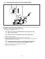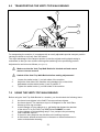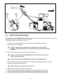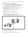
1
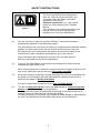
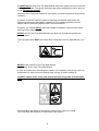
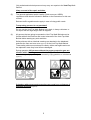
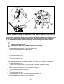
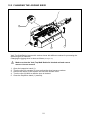
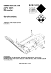
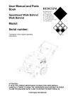
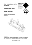
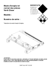
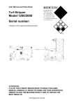
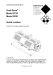
User Manual and Parts
Book of the Verti-Top
Walk Behind®
Model:
Serial number:
ATTENTION:
IT IS OF THE UTMOST IMPORTANCE TO READ THIS USER MANUAL CAREFULLY
PRIOR TO USING THE VERTI-TOP WALK BEHIND® IN ORDER TO USE THE MACHINE
SAFELY AND TO OBTAIN THE BEST RESULTS.
0948 English 947.120.206
FOREWORD
Congratulations on your Verti-Top Walk Behind purchase! For safe and long-lasting operation of
this Verti-Top Walk Behind, it is necessary to read and to understand this user manual.
It is impossible to work safely with this machine without complete knowledge of its content.
The following pages deal initially with the general safety instructions. Every user should know
these safety instructions and apply them. At the end of this page, a registration card is inserted.
This registration card should be returned to enable us to deal with potential future claims.
This user manual lists many instructions that are numbered in sequence. You should follow this
sequence. A
is an indication of a safety instruction. A
means a tip and/or note.
All information and technical specifications provided at the moment that this document is
published are the most recent ones. Design specifications may be changed without prior notice.
This document is a translation of the original operating instructions.
Upon request, the original operating instructions are available in Dutch.
WARRANTY CONDITIONS
WITH DELIVERY THIS VERTI-TOP WALK BEHIND IS GUARANTEED AGAINST MATERIAL
DEFECTS.
THIS WARRANTY IS VALID FOR A PERIOD OF 12 MONTHS FROM THE PURCHASE DATE.
VERTI-TOP WALK BEHIND WARRANTIES ARE SUBJECT TO THE ‘GENERAL CONDITIONS
FOR SUPPLY OF PLANT AND MACHINERY FOR EXPORT, NUMBER 188’ THAT ARE
PUBLISHED UNDER THE AUSPICES OF THE UNITED NATIONS ECONOMIC COMMISSION
FOR EUROPE.
REGISTRATION CARD
For your own information, fill in the table below:
Serial number machine
Dealer name
Date of purchase
Remarks
2
SAFETY INSTRUCTIONS
Figure 1
(1)
The Verti-Top Walk Behind is designed for
safe use. This can only be achieved if you
completely follow the safety instructions
described in this manual.
Read and understand (Figure 1) the manual
before you start using the Verti-Top Walk
Behind.
If the machine is not used as described in this
manual, this can result in injuries and/or
damage to the Verti-Top Walk Behind.
The user must be an expert in using the machine. The machine should be
professionally adjusted for cultivating the subsoil.
The manufacturer will not accept any liability for unprofessional use and its resulting
damage. All risks occurring with this are entirely at the expense of the user.
Not following the use, maintenance and repair instructions prescribed by the
manufacturer is also considered unprofessional use of this machine.
Inspect the area to be treated before using the Verti-Top Walk Behind.
Remove loose obstacles and avoid irregularities.
(2)
The Verti-Top Walk Behind is manufactured according to the latest technical
understanding and is safe to use.
When careless people use, maintain or repair the machine, danger of injuries to the
user and to third parties can be the result. This must be avoided!
(3)
All persons assigned to operate, maintain and repair the Verti-Top Walk Behind by
the owner must completely read and understand the operation manual and in
particular the chapter of Safety Instructions.
The user is responsible for safe use of the Verti-Top Walk Behind.
(4)
The user is obliged to check the Verti-Top Walk Behind for visible damage and
defects before using the Verti-Top Walk Behind.
Modifications to the Verti-Top Walk Behind (including its operations) that have a
negative impact on safety must be rectified immediately.
For safety reasons it is in principle not permitted to make changes or adjustments to
the Verti-Top Walk Behind (except those approved by the manufacturer).
3
If modifications to the Verti-Top Walk Behind have been made, then the current CE
marking is cancelled. The person that has made these modifications has to apply for
a new CE marking himself.
Check the Verti-Top Walk Behind for loose bolts, nuts and components before every
operation.
If present, check the hydraulic pipelines regularly and replace these when the
hydraulic pipelines are damaged or appear old. The replacing pipelines should
comply with the technical requirements of the manufacturer.
If present, you should always make the hydraulic installation pressure-free before
working on this installation.
NEVER use the Verti-Top Walk Behind in the absence of protective guards and
safety stickers.
The inspection hatch MUST be closed when using the Verti-Top Walk Behind (Figure
2).
Figure 2
NEVER crawl under the Verti-Top Walk Behind.
If necessary, tilt the Verti-Top Walk Behind.
In case of maintenance, adjusting and repairs, it is necessary to block the Verti-Top
Walk Behind in order to prevent sinking away, driving off and/or sliding off.
ALWAYS switch off the motor and detach the spark plug cable from the spark
plug in case of maintenance, adjustments and repairs (Figure 4).
Fig. 4
With regards to the safety of the machine and the user, use only original
Verti-Top Walk Behind parts for maintenance and repairs.
4
Only authorised technical personnel may carry out repairs to the Verti-Top Walk
Behind.
Keep a record of the repair activities.
(5)
The general applicable health & safety (Dutch acronym: ARBO)
regulations must also be followed in addition to the instructions in this user
manual.
Relevant traffic regulations also apply in case of using public roads.
Transporting persons is not permitted!
Do not use the Verti-Top Walk Behind in the dark, in heavy rain/storm or
on slopes with an angle larger than 20 degrees.
(6)
All persons that are going to operate the Verti-Top Walk Behind must be
familiar with all the functions and control elements of the Verti-Top Walk
Behind before starting any work activities.
Safety stickers with an identical meaning are attached to the sideboard,
and near the front and rear cover (Figure 8) of the Verti-Top Walk Behind.
These safety stickers must always be clearly visible and legible and must
be replaced in case they have become damaged.
During operation, NO persons without the proper protection gear are
allowed within the danger zone of the Verti-Top Walk Behind, because
there is danger of physical injuries caused by flying particles or substances
(Figure 5).
Figure 6
Figure 5
Onlookers without personal protection gear must keep a distance of
minimum 4 metres! (Figure 6)
5
Dress appropriately. Wear sturdy shoes with steel toecaps, long trousers
and tie up long hair. Do not wear loose clothing.
Use the proper personal protection gear according to the applicable health
& safety (Dutch acronym: ARBO) and safety regulations.
Figure 7
Use certified ear protection when using the machine! (Figure 7)
Figure 8
(7)
Location of the safety stickers (Figure 8).
6
TABLE OF CONTENTS
1.0
2.0
3.0
4.0
5.0
6.0
7.0
8.0
9.0
10.0
11.0
12.0
12.1
12.2
13.0
FOREWORD................................................................................................................. 2
WARRANTY CONDITIONS .......................................................................................... 2
REGISTRATION CARD ................................................................................................ 2
SAFETY INSTRUCTIONS ............................................................................................ 3
TECHNICAL DATA ....................................................................................................... 8
FIRST INSTALLATION – TAKING THE MACHINE OFF THE PALLET......................... 9
LIST OF GENERAL COMPONENTS ...........................................................................10
ADJUSTING THE WORKING DEPTH OF THE BRUSH ..............................................11
ADJUSTING THE ANGLE OF THE JIGGING SIEVE ...................................................12
TRANSPORTING THE VERTI-TOP WALK BEHIND ...................................................13
USING THE VERTI-TOP WALK BEHIND ....................................................................13
START/STOP PROCEDURE .......................................................................................14
EMPTYING THE WASTE RECEPTACLE ....................................................................16
TROUBLE SHOOTING (PROBLEM ANALYSIS) .........................................................17
EU DECLARATION......................................................................................................17
MAINTENANCE ...........................................................................................................18
ADJUSTING THE TENSION OF THE V-BELTS ..........................................................19
CHANGING THE JIGGING SIEVE...............................................................................21
OPTIONS FOR OTHER JIGGING SIEVES..................................................................22
7
1.0
TECHNICAL DATA
Model
V-Top WB
Working width
800mm
Working depth (In case of a nonworn brush)
Speed
0 mm-10mm (0”-0.4”)
Weight
0 – 3.5 km/h
0 – 2.5 mph
150 kg (330 lbs)
Content of the receptacle
30 litres (1830.7 cu. inch)
Maximum capacity
2800 m2/h (30139 ft2/h)
(Theoretical at maximum speed of 3.5 km/h
[2.5mph])
Motor
Briggs and Stratton 6.5 HP
Mesh of jigging sieve
5 mm x 5 mm (0.2 “ x 0.2”)
(Standard supplied)
Transport dimensions
LxWxH
1,070 x 1,035 x 1,305 mm
42.1” x 40.7” x 51.4”
Oil gearbox
SAE 30
Motor oil
SAE 30
Standard components
Jigging sieve, adjustable according to cleaning level
Removable waste receptacle
Easily exchangeable sieve
Cylinder for the manual including a manual
Optional
Sieve elements with various mesh dimensions
8
2.0
FIRST INSTALLATION – TAKING THE MACHINE OFF THE PALLET
1
2
3
4
6
5
7
Figure 9
The machine in transport position is delivered on a pallet. To remove the pallet and to prepare
the machine, you take the following steps (see Figure 9):
NEVER crawl under the machine!
1.
2.
3.
4.
5.
Remove the straps (1) with which the machine is fixed to the pallet.
Open the inspection hatch (4).
Remove the bolt and nut (2) on both sides of the machine.
Lower the handlebar (3) and mount bolts and nuts (2) when the correct position
has been reached.
Attach a cable to the lifting eyes (5 and 6).
Make sure that the cable/crane/lift can hoist minimum 200 kg (441 lbs).
6.
Lift the machine off the pallet (7).
WATCH OUT AND KEEP YOUR DISTANCE!
7.
Lower the machine controlled and calmly until it stands completely on the subsoil.
9
3.0
LIST OF GENERAL COMPONENTS
Figure 10 shows several important components:
16
14
9
2
15
1
3
11
6
5
17
2
4
9 8
10
13
12
7
Figure 10
1.
2.
3.
4.
Safety sticker 900.280.402; first read the user manual / toolbox before
using it.
Safety sticker 933.280.402; onlookers without personal protection gear
must keep a distance of 4 metres from the machine. Switch off the motor
and detach the spark plug cable from the spark plug in case adjustment or
repair is necessary. Watch out for flying particles!
The serial number is located at the front side of the machine.
Safety sticker 911.280.404; the inspection hatch MUST be closed when
using the machine.
All the safety stickers should be on the machine at all times and
should be understood.
5.
6.
7.
8.
9.
10.
11.
12.
13.
14.
15.
16.
17.
Adjustment device for adjusting the working depth
Knob for adjustment to the transport position
Waste receptacle
Jigging sieve adjustable according to cleaning level
Adjusting handle of the angle of the jigging sieve
ON/OFF switch
Choke
Start cord
Fuel valve
Throttle
Drive handle
Clutch handle of drive mechanism
Rotating brush
10
1
Figure 11
4.0
ADJUSTING THE WORKING DEPTH OF THE BRUSH
The working depth of the brush can be adjusted by adjusting the stellar knob at the front side of
the machine.
The procedure is as follows (see Figure 11):
Make sure that the Verti-Top Walk Behind is blocked well and
cannot move on its own accord!
Switch off the Verti-Top Walk Behind before making adjustments!
1. If this has not been done yet, put the spindle in the upper position
of the slotted hole.
2. Turn the spindle (1) until the correct position has been reached.
NEVER adjust the machine in such a way that it could damage the subsoil.
IMPORTANT!
First check the working depth on the subsoil statically before using the machine!
Experience shows that the machine adjustment for top-layer cleaning is best if the
brush hairs just don’t touch the grass fibres.
11
5.0
ADJUSTING THE ANGLE OF THE JIGGING SIEVE
3
2
1
Figure 12
If the receptacle is catching too much material that should have been sieved, it is possible to allow
the jigging sieve more time for sieving the material.
This is done by placing the jigging sieve under an angle.
The procedure is as follows (see Figure 12):
Make sure that the Verti-Top Walk Behind is blocked well and cannot
move on its own accord!
Switch off the Verti-Top Walk Behind before making adjustments!
1. Open the inspection hatch (1).
2. Loosen the stellar knobs (2) one turn on both sides of the machine.
3. Adjust the jigging sieve so that it is parallel and at the required angle. For this purpose,
make use of the indication stickers (3).
It is important that the jigging sieve is parallel adjusted on both sides
of the machine; if this is not done, you can damage the machine.
4. Tighten the stellar knobs (2) on both sides of the machine.
5. Close the inspection hatch (1).
12
6.0
TRANSPORTING THE VERTI-TOP WALK BEHIND
2
1
3
Figure 13
For transporting the machine, it is equipped with an easily adjustable special transport position
causing the brush to run freely from the subsoil.
The major advantage of the transport position is that the original working depth setting is
maintained so that you can continue working after switching to the processing position.
Adjustment is carried out as follows (see Figure 13):
Make sure that the Verti-Top Walk Behind is blocked well and cannot
move on its own accord!
Switch off the Verti-Top Walk Behind before making adjustments!
1.
2.
3.
7.0
Loosen the stellar knobs (1) on both sides of the machine.
Adjust the front side of the machine using handgrip (2) so that it tilts
backwards and the stellar knobs (1) are in position 3.
Tighten the stellar knobs (1) on both sides of the machine.
USING THE VERTI-TOP WALK BEHIND
Before using the Verti-Top Walk Behind in a location, you should check the following items:
1.
2.
3.
4.
5.
6.
Are there loose objects in the field? First remove these objects.
Are there slopes? The maximum slope is 20 degrees for the Verti-Rake.
Always go from top to bottom.
Is there danger of flying objects (e.g., golf balls) that distract the attention
of the driver? If so, the Verti-Top Walk Behind CANNOT be used.
Is there danger of sinking/sliding away? If so, postpone the processing
until conditions improve.
If the soil is wet, postpone the activities until conditions improve.
A field can be worked several times in the same or different directions in
order to obtain better cleaning.
13
1
3
2
Figure 14
8.0
START/STOP PROCEDURE
The start procedure is VERY important. If this procedure is not executed as described below, serious
damage to the machine / subsoil could be the result.
The start procedure is as follows (see Figure 14):
1. Check the Verti-Top Walk Behind for loose components and look whether all
components function properly.
If loose components are observed or components do not function
properly, the problems must be solved before using the Verti-Top Walk
Behind!
2. Drive to the spot where the processing should take place.
Make sure that the Verti-Top Walk Behind is blocked well and cannot
move on its own accord!
Switch off the Verti-Top Walk Behind before making adjustments!
3. Put the machine in the processing position and adjust the working depth of the machine
statically as described in Chapter 4.0.
Wear the proper personal protection gear!
4. Start the motor with a low number of revolutions.
(Please refer to the supplied motor manual for the start procedure of the motor.)
5. Pull the drive handle (1) towards the handlebar: The machine will move forward.
6. Increase the number of revolutions to the maximum by adjusting the throttle (2).
14
The drive should be disengaged for pulling the machine backwards. The procedure is as follows
(see Figure 14):
1. Release the drive handle (1): The drive will disengage.
2. Decrease the number of revolutions by adjusting the throttle (2).
Wait until the machine comes to a standstill before disengaging; if this
is not done, you can cause severe damage / wear & tear to the clutch!
3. Pull the clutch handle (3) backwards so that the machine is released.
4. Manoeuvre until it winds up in the correct position.
5. Move the clutch handle (3) forward and push the machine slightly forward; the clutch will
re-engage automatically.
6. Pull the drive handle (1) towards the handlebar: The machine will move forward.
7. Increase the number of revolutions by adjusting the throttle (2).
Stopping occurs as follows (see Figure 14):
1. Release the drive handle (1): The drive will disengage.
2. Decrease the number of revolutions by adjusting the throttle (2).
3. Stop de motor.
The Verti-Top Walk Behind is standard adjusted to drive straight.
This can easily be adjusted so that short bends can be taken (e.g., for cleaning
around a pole). The procedure is as follows (see Figure 15):
1
Figure 15
1. Loosen the stellar knobs (1) and remove them.
Now the front wheels can turn so that you can take bends.
Take bends carefully so that damage to the subsoil is avoided.
15
9.0
EMPTYING THE WASTE RECEPTACLE
1
2
3
Fig. 16
The waste receptacle should be emptied when the receptacle is full.
The procedure is as follows (see Figure 13):
1. Drive the Verti-Top Walk Behind to the waste-collection dump.
Make sure that the Verti-Top Walk Behind is blocked well and cannot
move on its own accord!
Switch off the Verti-Top Walk Behind before proceeding!
2.
3.
4.
5.
6.
7.
Open the rear inspection hatch (1).
Remove the pin and safety clip (2).
Remove the waste receptacle (3) and empty it.
Hang the waste receptacle (3) back in the machine.
Mount the pin and safety clip (2) so that the waste receptacle (3) is fixed.
Close the inspection hatch (1).
Remove waste according to the applicable stipulations of the local legislation.
16
10.0 TROUBLE SHOOTING (PROBLEM ANALYSIS)
Problem
The waste receptacle has
collected too much material
that needs to be cleaned
Possible cause
-
Jigging sieve is
adjusted too flat
-
-
Working depth is
adjusted too deep
Jigging sieve is
clogged
Surroundings are too
wet
Jigging sieve has a
mesh that is too small
-
-
Too little cleaning
Solution
-
Sloppy image of the field after processing
Working depth is
adjusted too shallow
Sieve with too large a
mesh
Brush is worn out
Outlet opening of the
brush is blocked
V-belts are slipping
-
Adjust the jigging sieve
more under an angle (see
Ch. 5.0)
Adjust the machine to less
depth
Clean the jigging sieve
Wait till surroundings are
dried up.
Use a sieve with a larger
mesh.
Adjust the machine to
more depth
Replace sieve with a
smaller meshed sieve
Replace brush
Remove blockage
-
Span the V-belts and/or
adjust the idler tension
pulley (see Ch. 12.1)
Machine is adjusted
too deep
-
Adjust the machine to less
depth
Squeaking noises during the
machine’s operation
-
Bearings are worn out
-
Replace the bearings
Clutch for reversing doe not
release
-
Cable is stretched /
worn out
Clutch housing is
damaged
-
Adjust and/or replace the
cable
Repair and/or replace the
parts
Machine does not move
-
-
V-belts are slipping
-
-
V-belts are burnt
Defect in the
mechanical driveline
-
Span the V-belts and/or
adjust the idler tension
pulley (see Ch. 12.1)
Replace the V-belts
Repair and/or replace the
parts
11.0 EU DECLARATION
We – Redexim BV, Utrechtseweg 127, 3702 AC Zeist, Holland – declare entirely under our own
responsibility that the product
VERTI-TOP WALK BEHIND with a machine number as indicated on the machine and
indicated in this manual
to which this declaration relates is according to the stipulation of the 2006/42/EC directive for
machines.
Zeist, 01/10/09
A.C. Bos
Manager Operations & Logistics
Redexim Holland
17
12.0 MAINTENANCE
Time Schedule
Before every use
Check/Grease Point
Method
-
Check for loose
bolts/nuts
-
-
Presence and readability
of the safety stickers
-
Tighten loose bolts/nuts
with the correct
tightening moment
Replace these if not
present or damaged
(Please refer to Figure 8)
After the first 20 working
hours (new or repaired)
-
After every 100 working
hours or annually
Check the roller
bearings and the
driveline
Check for loose
bolts/nuts
-
If required, replace the
parts
-
Tighten loose
bolts/nuts with the
correct tightening
moment
-
Check the tension of the
V-belts
-
If necessary, adjust the
tension of the V-belts
(see Ch. 12.1)
-
Check the roller
bearings and the
driveline
Check for loose
bolts/nuts
-
If required, replace the
worn parts
-
Tighten loose bolts/nuts
with the correct
tightening moment
Adjust the tension of the
chain or – if required –
replace the chain
Adjust the tension of the
V-belts (see Ch. 16.1)
or – if required –
replace the V-belts
If necessary, replace
the brush
Use a universal chain
grease
-
Check the tension of the
chain in the driveline
-
-
Check the tension / wear
of the V-belts
-
-
Check the wear of the
brush
Grease the drive chain
-
-
-
Please refer to the supplied manual for maintenance of the motor/gearbox!
18
12.1 ADJUSTING THE TENSION OF THE V-BELTS
A
4
5
1
2
3
Figure 17
The Verti-Top Walk Behind is standard equipped with adjustable tension pulleys that keep the Vbelts taut.
The system can be divided into 2 segments.
1. Tension pulley for the drive of the brush (see Figure 17)
2. Variable tension pulley for the drive of the entire
machine (1) (see Figure 18)
Depending on the intensity of using the machine, wear and tear can occur to the driveline
resulting in slipping of the V-belts.
These V-belts should then be tightened.
Adjusting the tension pulleys is done as follows:
Make sure that the Verti-Top Walk Behind is blocked well and cannot
move on its own accord!
Switch off the Verti-Top Walk Behind before proceeding!
1. Detach the spark plug cable (1) from the spark plug.
2. Remove all nuts (2) and the safety cap (3).
Tension pulley for the drive of the brush (see Figure 17)
1. Loosen the nut (4) slightly so that the tension is just off.
2. Adjust the tension pulley (5) until the correct tension has been reached.
3. Check the tension of the V-belt by pulling on point A with a tension of 2.5 kg
(5.5lbs). The stretch should be 2 mm (0.08”).
4. Tighten the nut (4).
5. Return the safety cap (3) to its location and mount all nuts (2).
6. Attach the spark plug cable (1) to the spark plug.
19
8
6 7
9
4 5
8
1
2
3
4 5
9
6 7
Figure 18
Variable tension pulley for the drive of the entire machine (see Figure 18)
For the proper functioning of the drive, it is important that the V-belts can slip and are not
driven if the tension pulley has been switched off. When the tension pulley is switched
on, the V-belt should couple and should engage with the pulley of the motor without
slipping.
Make sure that the Verti-Top Walk Behind is blocked well and cannot
move on its own accord!
Switch off the Verti-Top Walk Behind before proceeding!
1. Detach the spark plug cable (1) from the spark plug.
2. Remove all nuts (2) and the safety cap (3).
Adjusting the variable tension pulley is done as follows:
First of all, by precision adjustment:
1. Loosen the lock nuts (4).
2. Turn the little screwed tubes (5) outward until the correct tension has been reached.
3. Tighten the lock nuts (4).
If the required tension has not yet been reached, the cable can be adjusted a larger step;
the procedure is as follows:
1. Loosen the lock nuts (4).
2. Turn the little screwed tubes (5) on both sides of the cable completely inward.
3. Loosen the bolts (6) and the nuts (7) (at the side of the handle or the motor).
4. Move the bolts (6) and the nuts (7) to the desired holes (8).
5. Connect the cable (9) to the bolts (6) and the nuts (7).
6. Tighten the bolts (6) and the nuts (7).
7. Turn the little screwed tubes (5) outward until the correct tension has been reached.
8. Tighten the lock nuts (4).
9. Return the safety cap (3) to its location and mount all nuts (2).
10. Attach the spark plug cable (1) to the spark plug.
20
12.2 CHANGING THE JIGGING SIEVE
2
1
3
Figure 19
Verti-Top Walk Behind comes with various sieves with different meshes for processing the
different types of materials.
Changing the jigging sieve is done as follows (see Figure 19):
Make sure that the Verti-Top Walk Behind is blocked well and cannot
move on its own accord!
1.
2.
3.
4.
5.
Open the inspection hatch (1).
Turn the clips (2) a quarter of a turn so that the sieve becomes undone.
Remove the sieve (3) and replace this one with another sieve.
Turn the clips (2) back so that the sieve is blocked.
Close the inspection hatch (1) carefully.
21
13.0 OPTIONS FOR OTHER JIGGING SIEVES
It is possible to mount another sieve with a larger or smaller mesh if a different type of
material has to be sieved or the material has other dimensions for which the standard
mounted jigging sieve is inadequate.
The following sieves are available for the Verti-Top Walk Behind:
Mesh (mm)
3.2x3.2
4x4
5x5
5.5x5.5
6x6
Mesh (inch)
0.13x0.13
0.16x0.16
0.2x0.2
0.21x0.21
0.24x0.24
22
Spare part number
458.823.401
458.823.402
458.823.400 (Standard)
458.823.403
458.823.404