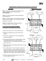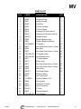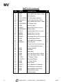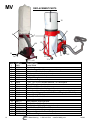
1
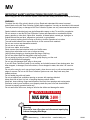
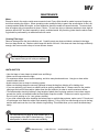
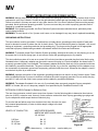
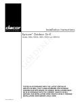
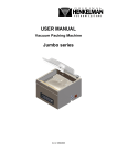
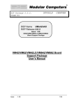
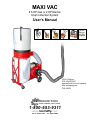
MAXI VAC
5.5 HP Gas or 2 HP Electric
Dust Collection System
User’s Manual
Use the
Maxi Vac
with your
equipment
FS050
FS200
SPS10
LNX8
X3
VM 5.5 Deluxe
P/N: VM1070003
depicted with 2 micron canister
filter w/cleaning bar
P/N: VM23
SMITH MANUFACTURING
CUTTERS / REMOVERS / PARTS / SUPPORT
1-800-653-9311
www.SmithMfg.com
Phone: 954-941-9744 • Fax: 954-545-0348
MV
INDEX
Page
2
Index
3
Safety Instructions for all Power Tools
4
Safety Instructions for Dust Collectors
5
Maintenance
6
Safety Instrauctions for Power Supply
7
Converting your Dust Collector to 220 Volts
8
Troubleshooting
9-10
Parts List
11
Exploded Parts Diagram
12
Replacement Parts
13-14
Filter w/Cleaner Bar - Parts List & Assembly
15
Maintenance Log
16
Limited Equipment Warranty Info
17
Warranty Activation
2
Contents
SMITH Manufacturing
1-954-941-9744
www.SmithMfg.com
1/2008
MV
SAFETY INSTRUCTIONS FOR ALL POWER TOOLS
1. KNOW YOUR EQUIPMENT. Read and understand owner’s manual and labels affixed to the equipment.
Learn its application and limitations as well as the specific potential hazards peculiar to this equipment.
2. GROUND THE EQUIPMENT. This machine is equipped with an approved 3-conductor cord and a 3-prong grounding type plug to fit the proper grounding type receptable. The green conductor in the cord is the
grounding wire. Never connect the ground wire to a live terminal.
3. KEEP GUARDS IN PLACE. Guards must be in working order, and in proper adjustment and alignment.
4. REMOVE ADJUSTING KEY AND WRENCHES. From a habit of checking to see that keys and adjusting
wrenches are removed from the tool before turning it on.
5. KEEP WORK AREA CLEAN. Cluttered areas and benches invite accidents.
6. AVOID DANGEROUS ENVIRONMENT. Do not use power tools in damp or wet locations or expose them
to rain. Keep work area well lighted. Provide adequate surrounding workspace.
7. KEEP CHILDREN AWAY. All visitors (especially children) should be kept a safe distance from the work
area.
8. MAKE WORKSHOP CHILD-PROOF. Use padlocks, master switches and remove starter keys.
9. USE PROPER SPEED. This equipment will do the job better and safer when operated at the proper
speed.
10. USE RIGHT EQUIPMENT - Do not force the equipment or attachment to do a job for which it was not
designed.
11. WEAR PROTECTIVE APPAREL. Do not wear loose clothing, gloves, necklaces, or jewelry (rings, wrist
watches, etc.) to get caught in moving parts. Non-slip footwear is recommended. Wear protective hair
covering to contain long hair. Roll long sleeves above the elbow.
12. USE SAFETY GOGGLES. Wear safety goggles (must comply with ANSIZ87,1) at all times.
Everyday glasses have impact resistant lenses, but are NOT safety glasses. Also, use a face or dust mask
if a cutting operation is dusty, and ear protection (plugs or muffs) during extended periods of operation.
13. DO NOT OVERREACH. Keep proper footing and balance at all times.
14. MAINTAIN EQUIPMENT WITH CARE. Keep equipment sharp and clean for best and safest performance.
Follow instructions for lubricating and changing accessories.
15. DISCONNECT EQUIPMENT. Unplug the equipment before servicing, and when changing accessories or
attachments.
16. AVOID ACCIDENTAL STARTING. Make sure the switch is in the OFF position before plugging into a live
electrical outlet.
17. USE RECOMMENDED ACCESSORIES. Consult the owner’s manual for recommended accessories.
Follow the instructions that accompany the accessories. The use of improper accessories may cause
hazards.
18. NEVER STAND ON YOUR EQUIPMENT. Serious injury could occur if the equipment tips over.
Do not store materials such that it is necessary to stand on the equipment to reach them.
19. CHECK DAMAGED PARTS. Before further use of the equipment, a guard or other part that is damaged
should be carefully checked to ensure that it will operate properly and perform its intended function.
Check for alignment of moving parts, mounting, and any other conditions that may affect its operation.
A guard or other part that is damaged should be properly repaired ore replaced.
20. NEVER LEAVE THE EQUIPMENT RUNNING UNATTENDED. Turn power OFF. Do not leave MV Dust
Collection System until the impeller comes to a complete stop.
1/2008
NOTICE:
This dust collector is designed to remove small chips
and dust particles. It is not capable of handling metal
pieces, or large pieces or blocks of concrete or asphalt.
SMITH Manufacturing
1-800-653-9311
www.SmithMfg.com
3
MV
IMPORTANT SAFETY INSTRUCTIONS FOR DUST COLLECTORS
When using your MV Dust Collection System, follow the basic safety precautions, including the following
WARNING:
To reduce the risk of fire, electric shock or injury. Read and understand this owner’s manual
and all labels on the MV Dust Collection System before operation. Use only as described in this manual.
To avoid personal injury or damage to MV Dust Collection System use only recommended accessories.
Sparks inside the electrical parts can ignite flammable vapors or dust. To avoid fire or explosion:
Do not vacuum or use this MV Dust Collection System near flammable or combustible liquids,
gases, gasoline or other fuels, lighter fluid, cleaners, oil-based paints, natural gas, hydrogen, or
explosive dusts like coal dust, magnesium, grain dust, or gun powder.
Do not vacuum anything that is burning or smoking, such as cigarettes or hot ashes.
To avoid health hazards from vapors and dust, do not vacuum toxic materials.
Do not use or store near hazardous material.
Do not use on wet surfaces.
Put unit on a stable, level surface.
Route vacuum hose and electrical cord out of traffic areas.
Unplug from outlet when not in use or before servicing.
Unplug before changing or cleaning dust filter bag or chip bag.
Do not use without dust filter bag and/or chip bag in place.
Do not unplug by pulling on cord. To unplug, grasp the plug, not the cord.
Turn off controls before unplugging.
Do not use with damaged cord, plug or other parts.
If your MV Dust Collection System is not working, as it should because it has missing parts, has
been dropped, is damaged, was left outdoors, or was dropped in water, then take it to a service
center.
Do not pull or carry by cord, use cord as a handle, close door on cord, or pull cord around sharp
edges or corners. Do not run MV Dust Collection System over cord. Keep cord away from
heated surfaces.
Do not handle plug with wet hands.
Do not put objects into ventilation opening or vacuum with openings blocked.
Keep vents free of dust, lint, hair, or anything that may reduce airflow.
Keep hair, loose clothing, fingers and all parts of the body from openings and moving parts.
Extension cords in poor condition or not properly rated can pose a fire and shock hazard.
Connect to properly grounded outlet only.
Do not remove the inlet cover, doing so will alter the airflow and damage the motor.
MAX RPM: 3400
www.SmithMfg.com
1-800-653-9311
! WA R N I N G
FAILURE TO COMPLY WILL RESULT IN FAN BLADE DAMAGE
Warning!
Be sure to turn off engine and disconnect spark plug
before changing filter bags.
4
SMITH Manufacturing
1-954-941-9744
www.SmithMfg.com
1/2008
MV
MAINTENANCE
Motor:
Excessive dust in the engine could cause excessive heat. Every effort should be made to prevent foreign material from entering the engine. When operating under conditions likely to permit the accumulation of dust, dirt,
or waste material within the engine, a visual inspection should be made at frequent intervals. To remove dust,
blow off engine with a low-pressure air hose. Caution: To avoid eye injury or adverse reactions to dust, high air
pressure should NOT be used, especially in poorly ventilated areas. Any servicing (other than the above cleaning) should be performed by an authorized service center.
Cleaning Filter bags:
Remove the bags from the dust collection unit. Carefully empty any dust and debris contained in the bags,
then turn bags inside out. Shake or whisk bags with brush or broom. If this does not clean the bags sufficiently
enough, then vacuum with a shop or house vacuum cleaner.
WARNING: Do not wash collection bags for
any reason! Doing so will void your warranty!
HINTS AND TIPS
• Use duct tape or hose clamps to attach hose and fittings.
• Make sure all connections are tight.
• For maximum airflow, do not restrict opening, avoid too many bends and turns. Use pipe or hose with a
smooth inside surface.
• Avoid extreme rises or drops in a ducting system.
• Make sure that bag straps are securely tightened to keep the bag from blowing off or leaking dust.
• If you are restricting your hose to a machine with an opening smaller than 4”, always restrict to the smaller
opening at the hood of the machine (rather than the dust collector) in order to ensure maximum airflow.
• To eliminate static electricity buildup in long lengths of plastic hose or piping systems, insert a bare copper
ground wire (solid, not braided) inside the hose and/or wrap the outside. Connect one end to a ground on
the unit you’re working on (i.e.: saw, planer, scarifier).
• If you need a third hand when installing the bottom bags on multiple bag systems, make a set of ‘S’ hooks out
of coat hanger wire. Make the whole hook assembly approx. 3” long. Hook one side through a loop in the bag,
and the other end over the rim of the collector ring housing. This should allow you to mount the band clamp
easily.
You can connect your hose to sizes smaller than 4” by
using adapters from SMITH Manufacturing. Call your
sales person for details on sizes and availability.
1/2008
SMITH Manufacturing
1-800-653-9311
www.SmithMfg.com
5
MV
SAFETY INSTRUCTIONS FOR POWER SUPPLY
WARNING: Always make sure the voltage of motor and motor rating agree with the electrical system which is to be
connected to your Dust Collector. Connect to the right electrical system and use time delay fuse or circuit breaker.
Failure to connect in this way can result in injury from shock or fire. Your Dust Collection System must be properly
grounded. Not all outlets are properly grounded. If you are not sure that your outlet is properly grounded, have it
checked by a qualified electrician.
WARNING: If not properly grounded, this Dust Collection System can cause electrical shock, particularly when
used in damp locations.
WARNIING: To avoid shock or fire, if power cord is worn, cut or damaged in any way, have it replaced immediately.
GROUNDING INSTRUCTIONS
This dust collector must be grounded. If it malfunctions or breaks down, grounding provides a path of least resistance for electronic current to reduce the risk of electric shock. This dust collection system is equipped - with a cord
having an equipment - grounding conductor and grounding plug. The plug must be plugged into an appropriate
outlet that is properly installed and grounded in accordance with all local codes and ordinances.
WARNING: To maintain proper Dust Collection System grounding, whenever the outlet you are planning to use for
this power tool is of the two prong type, do not remove or alter the grounding prong in any manner.
This dust collection system is for use on a normal 120-volt circuit and has a grounded plug that looks like the plug
illustrated below. A temporary adapter may be used to connect this plug to a 2-pole receptacle. As shown below, if
a properly grounded outlet is not available. The temporary adapter should be used only until a grounded outlet can
be installed by a qualified electrician. The green colored rigid ear, lug, or the like, extending from the adapter, must
be connected to a permanent ground such as properly grounded outlet box cover. Whenever the adapter is used, it
must be held in place by a metal screw.
WARNING: Improper connection of the equipment grounding conductor can result in a risk of electric shock. Check
with a qualified electrician if you are in doubt as to whether the outlet is properly grounded. Do not modify the plug
provided. If it will not fit the outlet, have a proper outlet installed by a qualified electrician.
WARNING: The adapter illustrated is for use only if you already have a properly grounded 2-prong receptacle.
NOTE: In Canada, the use of a temporary adapter is not permitted by the Canadian Electrical Code.
EXTENSION CORDS (Example for Reference Only)
The use of any extension cord will cause some loss of power. Use the following table to determine the minimum
wire size (A.W.G.) extension cord. Use only 3-wire extension cords which have 3-prong grounding type plugs and
3-pole receptacles which accept the dust collector’s plug.
3-PRONG PLUG
For circuits that are farther away from electrical circuit box, the wire size must
be increased proportionately in order to deliver ample voltage to the dust
collector’s motor.
LENGTH OF CONDUCTOR
6
WIRE SIZES REQUIRED
AMERICAN WIRE GAUGE (AWG)
112 volt lines
0-25 feet
26-50 feet
51-100 feet
GROUNDING PRONG
GROUNDING PLUG
3-PRONG PLUG
No. 16
No. 14
No. 12
SMITH Manufacturing
1-954-941-9744
PROPERLY
GROUNDED OUTLET
ADAPTER
MAKE SURE THIS
IS CONNECTED TO
A KNOWN GROUND
3-PRONG
RECEPTACLE
Figure #1
www.SmithMfg.com
1/2008
MV
CONVERTING YOUR DUST COLLECTOR TO 220 VOLTS
Instructions
Wiring box sub-straight
110 Volts
Note 1: The bottom two wires are the AC input to the
motor system and remain in the same place.
DO NOT MODIFY.
(Pre-wired)
line #3
line #2
line #4
line #1
Note 2: The green ground wire inside the wiring box
remains where it is.
Note 3: The sub-straight is a feed through sub-straight
where the three terminals on the top are connected to
the three on the bottom.
Note 4: The middle section of the sub-straight is
not used for normal 110 volt operation.
Translucent
Cover
To convert 110V to 220V operation:
Terminals
not used
1) Disconnect power plug from the wall outlet.
2) Remove the screw and cover from the wiring box.
Wire
sub-straight
AC Input
Figure #2
3) Remove the translucent cover from the wire substraight.
220 Volts
4) The system is shipped in the 110 volt configuration,
as shown in figure #2.
5) On the upper left terminal you will find lines #1 and #3,
on the upper right you will find lines #2 and #4.
Disconnect line #3 from the upper left terminal, leaving
line #1 where it is.
line #2
(Converted)
line #3
line #4
line #1
6) Disconnect line #2 from the upper right terminal, leaving
line #4 where it is.
7) The middle section of this sub-straight is normally not
used on this system, so you can take advantage of it
being there. Take lines #2 and #3 and tie them together
using the normally un-used upper middle terminal as
in figure #3. Your system is now connected to 220 volts.
Wire
sub-straight
AC Input
8) Install the appropriate 220 volt plug to the cord. You
are now ready to run at 220.
1/2008
SMITH Manufacturing
1-800-653-9311
Figure #3
www.SmithMfg.com
7
MV
TROUBLESHOOTING
PROBLEM
POSSIBLE CAUSES
Motor will not run (gas).
Various
REMEDY SUGGESTED
Refer to Engine manual
Excessive dust in air
1. Connectors are loose
2. Filter/dust bag and/or chip
collection bag is releasing
dust
3. Bag mesh not tight enough
1. Tighten connections
2. Dust trapped between bag
clamp and housing, or
Lower bag may be hung up on
dust shoot extension, reposition bag properly
3. If using 50 micron bags, switch
to 2 micron filters.
Excessive impeller noise
Picked up large chips/debris
Impeller loose or rubbing
Stop machine and disconnect
spark plug (unplug from power
source if electric). Remove inlet
cover to clear of chips or debris.
Tighten mounting nut, if loose.
If mounting nut is tight then
loosen the 4 engine mounting
bolts and slide engine back.
Insufficient air flow
Excessive static pressure or
air leaks
Clean collector bags
Remove any air flow restrictions
Enlarge the hose and/or
connections to the largest
openings possible.
Drop down to port size as close
as possible to the hood.
Bypass any 2nd stage container.
Re-run excessive rises or sharp
turns in duct system.
Check for open gates and/or
leaks at connector points.
Vibration
1. Loose, unbalanced or
bent impeller
2. Cracked engine mount
1. Stop machine and disconnect
spark plug (unplug from power
source if electric).
Remove inlet cover and tighten
mounting nuts.
Replace impeller, if needed
2. Replace engine
8
Warning!
Be sure to turn off engine and disconnect
spark plug before servicing your unit.
SMITH Manufacturing
1-954-941-9744
www.SmithMfg.com
1/2008
MV
PARTS LIST
ILL#
1
2
3
4
5
6
7
8
9
10
11
12
13
14
15
16
17
18
19
19.1
20
21
22
23
24
25
26
27
28
29
30
1/2008
PART#
DESCRIPTION
VM03.1
VM31
VM03.1
VM07
VM16
VM19
VM19.1
VM19.2
VM20
VM21
V.SC30M219
VM27
VM35
VM27
V.SC30m219
V.SC30m190
VM17
VM17.1
VM27
VM28
VM33
VM33.5
VM33.1
VM11
10101802
VM06
VM13
VM16.1
VM16.5
VM32
V.SC30M190
Collection Bags
Intake Housing
Dust Bag
63” Band Clamp
5” Hose Clamp
Hanging Rod (top section)
Hanging Rod (bottom section)
Hanger Socket
Support Bracket (top)
Support Bracket (bottom)
‘F’ Washer
Hex Head Screw, 8mm x 16mm
Nut, 8mm
Hex Head Screw, 8mm x 16mm
‘F’ Washer, 8mm
Lock Washer, 8mm
‘Y’ Hose Adapter
Plastic Cap
Hex Cap Screw, 8mm x 16mm
Hex Cap Screw, 8mm x 18mm
Inlet Cover
Pan Head Screw
Rubber Packing
Hex Cap Screw
Fender Washer, 5/16
Fan Impeller
Ventilation Cylinder
Hose Connector
5” Hose
Cylinder Bracket
Lock Washer
SMITH Manufacturing
1-800-653-9311
www.SmithMfg.com
QTY
1
1
1
2
2
1
1
1
3
3
12
6
6
16
22
10
1
1
10
6
16
10
1
1
1
1
1
1
1
1
8
9
MV
PARTS LIST (continued)
ILL#
31
32
33
33.1
34
35
36
37
38
39
40
41
42
43
44
45
46
47
48
49
50
51
52
53
54
56
57
58
59
60
61
62
10
PART#
DESCRIPTION VM27
VM22
RS-E-15026.0
FS2E-0100-2
VM28
V.SC30M219
VM35
N00202
V.SC30M219
620115
990861
994532
990853
VM30
VM40
168008.2
Hex Head Screw, 8mm x 16mm
Motor Bracket
5.5 HP Honda Gas Motor
2 HP Leeson Electric Motor
Hex Head Screw, 8mm x 18mm
‘F’ Washer, 8mm
Hex Nut, 8mm
Strain Relief (Electric Unit only)
VM41
VM42
VM43
VM28
VM27
110046
1012230.1
VM34
VM38
VM37.2
VM37.1
VM37
80001
SMITH Manufacturing
QTY
4
1
1
1
4
4
2
1
1
Washer, 8mm
1
Switch Holder (Electric Unit only)
2
Screw (Electric Unit only)
1
Switch (Electric Unit only)
Grounding Screw (Electric Unit only) 2
2
8” Solid Rubber Wheel
2
Axle Shaft Plate Assembly
2
Hitch Clip Pin
1
Power Cord (Electric Models Only)
1
Key (comes with gas motor)
1
Vacuum Gasket
1
Left Base
1
Right Base
6
Hex Cap Screw, 8mm x 18mm
4
Hex Cap Screw, 8mm x 16mm
2
‘F’ Washer, 5/8mm
12
Structrual Washer
2
4” Caster Wheel
1
Brace Plate
1
Front Stabilizer (not shown)
1
Side Stabilizer (not shown)
1
Rear Stabilizer (not shown)
1
Serial Number Plate
1
Warning Label
1-954-941-9744
www.SmithMfg.com
1/2008
EXPLODED PARTS DIAGRAM
MV
1/2008
SMITH Manufacturing
1-800-653-9311
www.SmithMfg.com
11
MV
REPLACEMENT PARTS
15
8
3
7
24
19
4
18
21
21
1
2
12
ILL #
1
2
3
4
5
6
7
8
9
10
11
12
13
14
15
16
17
18
19
20
21
22
23
24
PART #
VM01
VM02
VM03.1
VM04
VM05
VM06
VM07
VM08
VM09
VM10
VM11
VM12
VM13
VM14
VM23
VM30
VM34
VM37.2
VM37.1
VM37
VM38
1068055
SPSE-0120
FS2E-0100-2
3
13
16
17
DESCRIPTION
Caster Wheel
Wheel
Collection Bags, Set of 2 (one upper, one lower)
50’ Vacuum Hose, black
50” Vacuum Hose, clear (not shown)
25’ Intake Hose (not shown)
63” Band Clamp
5.5 HP Honda Engine
1” OD, .751” ID, 3/4” shoulder diameter, .62” thick spacer
1/8” x 3/8” pop rivet (not shown)
5/16-18 x 1-1/2” hex head bolt
5/16-24 x 1-1/4” hex head bolt grade 8
Blower Assembly with impellor, blower housing, and mounting bracket
Blower Assembly complete with 5.5 HP Honda Engine (incl. ILL # 13)
2micron Canister Filter
8 x 2 1/2 Solid Rubber Wheel
4” Stem Caster Wheel
Front Stabilizer Support Bracket
Side Stabilizer Support Bracket
Rear Stabilizer Support Bracket (not shown)
Base Stabilizer, Set of 2 Front & Rear
Tachometer (optional for gas engine)
Tachometer (required for electric engine)
2 HP Leeson Engine
SMITH Manufacturing
1-954-941-9744
www.SmithMfg.com
1/2008
MV
FILTER WITH CLEANER BAR
UNPACKING CONTENT
Unpack carton; please check the contents per parts list below:
A
C
D
B
PARTS LIST
A. Canister Filter
B. Cleaning Bar
C. Belt Clamp
D. Foam 4 x 20 x 1620mm (2)
1/2008
SMITH Manufacturing
1-800-653-9311
www.SmithMfg.com
13
MV
ASSEMBLY STEP
Step 1
Mount the cleaning bar (B) on the top canister filter (A) by tightening the hex head screw M6 x
16mm (P/No.2). Please make sure the screw is locked tightly. Please see FIG. 1 and 2.
P/NO.2
B
A
FIG. 2
Step 2
FIG. 1
Stick the Foam (D) on the top of collector. Please see figure 3.
D
FIG. 3
Step 3
Place the complete Canister Filter (A) on the top area of collector and use the belt clamp (C) to
tighten. Please see figure 4.
A
C
FIG. 4
14
SMITH Manufacturing
1-800-653-9311
www.SmithMfg.com
1/2008
MV
MAINTENANCE LOG
WARRANTY CLAIMS
The manufacturer reserves the right to change or improve the machine design without assuming any
obligation to update any products previously manufactured before this manual. It is the customer’s
responsibility to complete the warranty card and mail it to the seller within 10 days from the date of
purchase. If a failure occurs during the warranty period, the customer must contact the seller to determine the appropriate action. Any and all transportation charges are to be borne by the purchaser.
1/2008
SMITH Manufacturing
1-800-653-9311
www.SmithMfg.com
15
MV
Limited Equipment Warranty
All statements, technical information and recommendations contained in SMITH’s literature are based on tests believed to be reliable, but the accuracy
or completeness thereof is not guaranteed and the following is made in lieu of all warranties, expressed or implied. SMITH warrants all equipment or part
referenced in this document which is manufactured by SMITH and bearing its name to be free from defects in material and workmanship on the date of
sale to the original purchaser under normal use and maintenance as herein provided. This warranty does not apply to components manufactured by others
such as, but not limited to, bearings and engines; such components that may or may not have their own warranties.
With the exception of any special, extended, or limited warranty published by SMITH, SMITH will, for a period of three months (90 days) from the
date of sale or up to five hundred (500) hours of use by buyer, whichever shall occur first; repair or replace any part of the equipment determined by
SMITH to be defective. This warranty applies only when the equipment or part is installed, operated and maintained in accordance with SMITH’s written
recommendations.
SMITH’s sole obligation for any breach of warranty or breach of contract for defects, deliberate or accidental omissions, shall be limited to repairing,
replacing or allowing credit for, at SMITH’s option, any part which, under normal and proper use and maintenance, proves defective in material or
workmanship within warranty period, provided, however, that notice of any such defect or omission and satisfactory proof thereof is promptly given by
buyer to SMITH, and thereafter, such defective part is returned to SMITH with transportation charges prepaid, and SMITH’s examination proves such part
to have been defective. This warranty does not obligate SMITH to bear any transportation charges or personnel time in connection with the replacement
or repair of defective parts. This warranty does not obligate SMITH to bear any expense for travel time or of personnel in connection with any service calls.
SMITH will not, in any event, be liable to the user for any consequential damages arising out of this sale for the loss of use, lost profits or revenue, interest,
lost goodwill or work stoppage. SMITH shall not be liable for any injury, loss or damage, direct or consequential, arising out of the use or the inability to use
the product or for environmental claims. It being understood that SMITH has no means of controlling the products final use; therefore, it shall be buyer’s
responsibility to determine suitability of product for intended use and buyer assumes all risks and liabilities whatsoever, in connection therewith. In no event
shall SMITH be liable for consequential or special damages. Used products are sold on an “as is” basis, and there is no implied warranty of merchantability
or of fitness for a particular purpose, unless made in writing by an officer at SMITH’s office.
This warranty does not cover, and SMITH shall not be liable for general wear and tear, or any malfunction, damage or wear caused by faulty installation,
misapplication, abrasion, corrosion, inadequate or improper maintenance, negligence, accident, tampering, or substitution of non-SMITH component parts.
Nor shall SMITH be liable for malfunction, damage or wear caused by the incompatibility of SMITH equipment with structures, accessories, equipment
or materials not supplied by SMITH, or the improper design, manufacture, installation, operation or maintenance of structures, accessories, equipment
or materials not supplied by SMITH. This warranty does not apply in respect to damages to any product or accessory or attachment thereof caused by
overloading or other misuse, neglect or accident, nor does this warranty apply to any product or accessory or attachment thereof, which has been repaired
or altered in any way which, in the sole judgment of SMITH, affects the performance, stability or general purpose for which it was manufactured. In the
manufacture of buyer’s equipment, parts may be omitted or equivalent functioning equipment and components may be substituted for the original specified
equipment upon the sole judgment and discretion of SMITH.
This warranty is conditioned upon the prepaid return of the equipment claimed to be defective to an authorized SMITH Reseller for verification of the
claimed defect. If the claimed defect is verified, SMITH will repair or replace free of charge any defective parts and return of merchandise back to the
customer freight collect. If inspection of the equipment does not disclose any defect in material or workmanship, repairs will be made at a reasonable
charge, which charges may include the costs of parts, labor and transportation.
THIS WARRANTY IS EXCLUSIVE AND IS IN LIEU OF ANY OTHER WARRANTIES, EXPRESS OR IMPLIED, INCLUDING BUT NOT LIMITED TO
WARRANTY OF MERCHANTABILITY OR WARRANTY OF FITNESS FOR A PARTICULAR PURPOSE.
SMITH’s sole obligation and buyer’s sole remedy for any breach of warranty shall be as set forth above. The buyer agrees that no other remedy (including,
but not limited to, incidental or consequential damages for lost profits, lost sales, injury to person or property, or any other incidental or consequential loss)
shall be available. Any action for breach of warranty must be brought within two (2) years of the date of sale.
SMITH MAKES NO WARRANTY, AND DISCLAIMS ALL IMPLIED WARRANTIES OF MERCHANTABILITY AND FITNESS FOR A PARTICULAR
PURPOSE, IN CONNECTION WITH ACCESSORIES, EQUIPMENT, MATERIALS OR COMPONENTS SOLD BUT NOT MANUFACTURED BY SMITH.
These items sold, but not manufactured by SMITH (such as electric motors, switches, hose, etc.), are subject to the warranty, if any, of their manufacturer.
SMITH will provide purchaser with reasonable assistance in making any claim for breach of these warranties. In no event will SMITH be liable for indirect,
incidental, special or consequential damages resulting from SMITH supplying equipment hereunder, or the furnishing, performance, or use of any products
or other goods sold hereto, whether due to a breach of contract, breach of warranty, the negligence of SMITH, or otherwise.
ADDITIONAL WARRANTY COVERAGE - SMITH does provide extended warranty and wear warranty for products.
Corrections - typographical or clerical errors contained herein are subject to correction by SMITH.
Assignment - buyer shall not assign or transfer this warranty without SMITH’s written consent.
Entire agreement and applicable law - the rights and obligations of SMITH and buyer shall be governed by the laws of the state of Florida, U.S.A. In force
on date hereof. The provisions hereof are intended by buyer and SMITH as a final expression of their agreement, and are intended also, as a complete
and exclusive statement of all terms apply cable to buyer’s order. No waiver, modification, or addition to any of the terms hereof shall be binding on SMITH,
unless made in writing by an officer at SMITH’s office as stated herein. In the event of conflict between buyer’s purchase order and the terms hereof, the
latter shall control. If any provisions herein are to any extent invalid or unenforceable, the remainder of the warranty shall not be effected thereby and shall
be valid and enforceable to the fullest extent permitted by law.
Legal action - buyer shall be responsible for all costs of collection of outstanding indebtedness, including but not limited to attorney’s fees and court costs
to seller. Buyer shall reimburse seller for any and all litigation expenses seller incurs as a result of an unsuccessful buyer claim. The jurisdiction and venue
of the court for any litigation, state or federal, brought by the buyer and/or seller shall be located in venue determined by seller.
Fair labor standards - seller’s products are produced in the United States and in conformity with all applicable provisions of the fair labor standards act of
1938 as amended and any regulations and orders of the United States Department of Labor issued thereunder.
All written and visual data contained in this document reflects the most current product information available at the time of this publication. SMITH reserves
the right to make changes at any time without notice.
TO ORDER, contact your SMITH distributor or call 1-800-653-9311 to identify the nearest distributor.
SMITH Manufacturing Co, Inc.
1610 South Dixie Highway
Pompano Beach, FL 33060
www.smithmfg.com
16
SMITH Manufacturing
1-800-653-9311
www.SmithMfg.com
MV
Pre-Operation Inspection - Warranty Activation
Product Registration
Thank you for purchasing a SMITH. Please complete this form upon receipt of your equipment and prior to use on
the job. A pre-operation inspection is required to activate your warranty. All sections must be completed. Should
you have any questions, please add to the comments section below. Fax completed form to (954) 545-0348.
Organization_ ___________________________________________________________________________
First Name ____________________________________ Last Name: _______________________________
Job Function (Title) ________________________________________________________________________ Phone: _ ______________________________________ Email:____________________________________
Address _ ______________________________________________________________________________
City_ ___________________________________________ State_ _____________ Zip _________________
MV 5.5 or MV 2E
SMITH Product_ _____________________________
Machine Serial #_ ______________________________
Date of Purchase (MM / DD / YYYY) ______________ Purchased from_______________________________
Pre-Operation Inspection (please check all)
1. No parts or components on the machine appear damaged or lost in shipment.
2. All bolts and fasteners are in place and tightly secured.
Yes
Yes
No
No
3. Grease points have been identified for future maintenance requirements and appear lubricated.
4. Wheels are operational.
Yes
Yes
No
No
5. Motor has been started and in good working condition.
6. All Decals appear in place and securely attached.
Yes
Yes
No
No
7. Equipment runs and tested to assure all components are operating correctly.
8. Do you have a Wear Parts Kit with an Extra Cutter set in stock?
Yes
Yes
No
No
9. Did you join Remove Faster News for tech updates, experience sharing and special offers?
Yes
No
Comments (add any additional or from above answers below)
______________________________________________________________________________________
______________________________________________________________________________________
Special offer for Wear Parts Kit and Carbide Cutter
drum if purchased within 30 days after activation.
SMITH Manufacturing
Signature: ____________________________________
1-800-653-9311
www.SmithMfg.com
17
SMITH Manufacturing
1610 South Dixie Highway
Pompano Beach, FL, 33060
Toll Free: 800.653.9311
Phone: 954.941.9744
Fax: 954.545.0348
Email: [email protected]
Web: www.SmithMfg.com
Authorized Distributor: