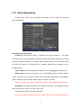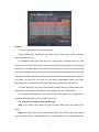
1
HN4 Series Net DVR User Manual V2.1S Thank you for purchasing our embedded Net DVR. This manual is applicable for HN series Net DVR. Please read this User Manual carefully to ensure that you can use the device correctly and safely. The contents of this Manual are subject to change without notice. 1 Safety Precaution .............................................................................................................. 4 Chapter1 Product Introduction..................................................................................... 7 1.1 Summary ................................................................................................................... 7 1.2 Features ..................................................................................................................... 7 1.3 Typical Application ................................................................................................. 10 Chapter2 Installation ................................................................................................. 11 2.1 Check DVR and It’s Accessories ............................................................................ 11 2.2 HDD Installation ..................................................................................................... 11 2.3 DVR Rear Panel ...................................................................................................... 14 2.4 External Alarm In/Out Connection ......................................................................... 14 2.5 Powering up ............................................................................................................ 15 Chapter3 Operational Instructions ............................................................................. 16 3.1 DVR Front Panel ..................................................................................................... 16 3.2 IR Control ............................................................................................................... 18 3.3 OSD Menu Description ........................................................................................... 20 3.3.1 Main Menu Items .......................................................................................... 20 3.3.2 Menu Operation ............................................................................................ 21 3.4 Character Input ........................................................................................................ 24 Chapter4 Basic Operation Guide............................................................................... 25 4.1 Power on ................................................................................................................. 25 4.2 Live View ................................................................................................................ 26 4.3 Login ....................................................................................................................... 29 4.4 PTZ Control ............................................................................................................ 30 4.5 Manual Record ........................................................................................................ 32 4.6 Playback .................................................................................................................. 34 4.7 Backup Recorded Files ........................................................................................... 38 4.8 Turn off DVR .......................................................................................................... 41 Chapter5 Advanced Operation Guide ....................................................................... 43 5.1 User Management ................................................................................................... 44 5.1.1 Add User ........................................................................................................ 45 5.1.2 Delete User.................................................................................................... 47 5.1.3 Password Modification ................................................................................. 48 5.1.4 User Rights .................................................................................................... 49 5.2 Device ID ................................................................................................................ 52 5.3 Video Standard and VGA Setup .............................................................................. 53 5.4 Day and Time Setup ................................................................................................ 54 5.4.1 Day and Time Setting................................................................................... 54 5.4.2 Day and Time Display Mode ....................................................................... 55 5.5.3 Daylight Saving Time Setup ........................................................................ 57 5.5 Camera Setup .......................................................................................................... 58 5.5.1 Camera Name Setup ................................................................................... 58 5.5.2 Video Parameters Setup ............................................................................. 59 5.6 Mask Area Setup ..................................................................................................... 61 2 5.7 5.8 5.9 5.10 5.11 5.12 5.13 View Tampering Alarm ........................................................................................... 63 Video Loss Alarm.................................................................................................... 64 Motion Detection Alarm ......................................................................................... 66 Live View Setup ...................................................................................................... 70 Recording Setup ...................................................................................................... 72 Alarm I/O Setup ...................................................................................................... 76 Network Setup......................................................................................................... 80 5.13.1 Network Basic Settings ................................................................................ 80 5.13.2 Network Advanced Settings ........................................................................ 81 5.13.3 DHCP Function ............................................................................................. 81 5.13.4 PPPoE Function ........................................................................................... 81 5.13.5 IP Server Solution for DHCP ...................................................................... 83 5.14 PTZ Setup ............................................................................................................... 84 5.14.1 PTZ Connection ............................................................................................ 84 5.14.2 PTZ Settings.................................................................................................. 84 5.14.3 PTZ Control ................................................................................................... 86 5.14.4 Preset Setup.................................................................................................. 86 5.14.5 Sequence Setup ........................................................................................... 87 5.14.6 Cruise Setup.................................................................................................. 88 5.16 Exceptions Setup ..................................................................................................... 89 Chapter6 Utilities ....................................................................................................... 90 6.1 Restore Parameters .................................................................................................. 91 6.2 Hard Disk Management .......................................................................................... 92 6.3 Clear Alarm Out ...................................................................................................... 92 6.4 Reboot ..................................................................................................................... 92 6.5 Power Off ................................................................................................................ 92 6.6 View Log ................................................................................................................. 92 6.7 System Information ................................................................................................. 95 Chapter7 Firmware Upgrade ..................................................................................... 96 7.1 Upgrade from USB Flash ........................................................................................ 96 7.2 Upgrade from FTP Server ....................................................................................... 97 7.2.1 FTP Server Setup ......................................................................................... 97 7.2.2 Use DVR FTP Upgrade Function ............................................................... 99 7.3 Use Client Software to Upgrade............................................................................ 100 Appendix A HDD Capacity Calculation ....................................................................... 101 AppendixA DVR Connector Definition ........................................................................... 102 Appendix B Specifications........................................................................................... 105 Appendix C recommended list ...................................................................................... 106 Appendix D Troubleshooting ........................................................................................115 Appendix E Product Service ........................................................................................117 Appendix F Customer Information Card ......................................................................118 3 Safety Precaution Caution: To reduce the risk of electric shock, do not remove cover, (unless you wish to install hard disks, please see the section "Hard Disk Installation"). No User-serviceable parts inside. Refer servicing to qualified service personnel. Important Safeguards: 1. Read these instructions. 2. Keep these instructions. 3. Heed all warnings. 4. Follow all instructions. 5. Do not use this apparatus near water. 6. Clean only with a dry cloth. 7. Do not block any ventilation openings. Install in accordance with the manufacturer's instructions. 8. Do not install near any heat sources such as radiators, heat registers, stoves, or other apparatus (including amplifiers) that produce heat. 9. Do not defeat the safety purpose of the polarized or grounding-type plug. A polarized plug has two blades with one wider than the other. A grounding-type plug has two blades and a third grounding prong. The wide blade or third prong are provided for your safety. If the provided plug does not fit into the outlet, consult an electrician for replacement of the obsolete outlet. 10. Protect the power cord from being walked on or pinched particularly at plugs, convenience receptacles, and the point where they exit from the apparatus. 11. Only use attachments/accessories specified by the manufacturer. 12. Use only with the cart, stand, tripod, bracket, or table specified by the manufacturer, or sold with the apparatus. When a cart is used, use caution when moving the cart/apparatus combination to avoid injury from tip-over. 4 13. Unplug this unit during lightning storms or when unused for long periods of time. 14. Refer all servicing to qualified service personnel. Servicing is required when the apparatus has been damaged in any way, such as power-supply cord or plug is damaged, liquid has been spilled or objects have fallen into the apparatus, the apparatus has been exposed to rain or moisture, does not operate normally, or has been dropped. 15. Moving - Disconnect the power before moving the unit. The unit should be moved with care. Excessive force or shock may result in damage to the unit and the hard disk drives. 16. Power Sources - This unit should be operated only from the type of power source indicated on the marking label. If you are not sure of the type of power supply you plan to use, consult your appliance dealer or local power company. 17. Overloading - Do not overload outlets and extension cords as this can result in a risk of fire or electric shock. 18. Object and Liquid Entry - Never push objects of any kind into this unit through openings, as they may touch dangerous voltage points or short out parts that could result in a fire or electric shock. Never spill liquid of any kind on the unit. 19. Replacement Parts - When replacement parts are required, be sure the service technician has used replacement parts specified by the manufacturer or have the same characteristics as the original part. Unauthorized substitutions may result in fire, electric shock, or other hazards. 20. Coax Grounding - If an outside cable system is connected to the unit, be sure the cable system is grounded. U.S.A. models only--Section 810 of the National Electrical Code, ANSI/NFPA No.70-1981, get information from professional electrician to proper grounding of the mount and supporting structure, grounding of the coax to a discharge unit, size of grounding conductors, location of discharge unit, connection to grounding electrodes, and requirements for the grounding electrode. 21. To reduce the risk of fire or electric shock, this apparatus should not be exposed to rain or moisture and objects filled with liquids, such as vases, should not be placed on this apparatus. 5 22. Danger of explosion if battery is incorrectly replaced. Replace only with the same or equivalent type. Dispose of the replaced battery in an environmentally friendly way. Cleaning You can clean the unit with a moist fluff-free cloth or shammy leather cloth. Warning This device is intended for use in public areas only. Surreptitious recording of oral communications is may prohibited by law. Unpacking Check the package for visible damage. If any items appear to have been damaged in shipment, notify the shipping company. Unpack carefully. This is electronic equipment and should be handled with care to prevent damage to the unit. Do not attempt to use the unit if any components are damaged. If any items are missing, notify the dealer. The shipping carton is the safest container in which to transport the unit. Save it and all packing materials for future use. If the unit must be returned, use the original packing materials. Packaging contents The package should contain the following items: 1. Digital Video Recorder 2. Accessories box 6 Chapter1 Product Introduction 1.1 Summary HN series network digital video recorder is an excellent digital surveillance product. It uses the embedded MCU and embedded operating system (RTOS), combining the most advanced technology in Information Industry such as video and audio encoding/decoding, hard disk record and TCP/IP. The firmware is burned in the flash, more stable and reliable. HN series device has both the features of digital video recorder (DVR) and digital video server (DVS). It can work stand alone, also be used to build a powerful surveillance network, widely used in bank, telecommunication, transportation, factories, warehouse, irrigation, etc. 1.2 Features Compression z Support 16 channels video input (PAL/NTSC) at most. Each channel is independent, H.264 hardware compression and real time (PAL: 25 FPS, NTSC: 30FPS). Support both variable bit rate and variable frame rate z Support 16 channels audio input at most. Each channel is independent, OggVorbis compression and bit rate is 16Kbps z Compressed video and audio are synchronous. You can select either mixed stream or only video stream z Support CIF and QCIF recording resolution z Support multi area motion detection z Support OSD and changeable OSD position z Support LOGO and changeable LOGO position 7 Local functions Record z Support multiple record type, including real time, manual record, motion detection, external alarm, motion&alarm, motion|alarm z Support 4 SATA HDDs maximum and each HDD can support 2000GB maximum z Support FAT32 file system z Support HDD S.M.A.R.T technology z Support cycle or none cycle record z Support backup the recorded files and clips. Support USB memory, USB HDD, USB CD/DVD, SATA CD/DVD writer for backup Preview and playback z Support BNC analog monitor and VGA output for main output z Support multiple preview modes z Support sensitive area mask z Support camera spiteful block alarm z Support 2-ch synchronous playback. Support play forward, backward, pause, frame by frame, etc z Support play back by files or by time z Display local record status PTZ z Support many kinds of PTZ protocol z Support preset, sequence and cruise Alarms z Support exception alarm, motion detection alarm, external alarm, etc Others z Support IR control z Support RS-485 keyboard z Support multi-level user management 8 Network z Support TCP, UDP, RTP, Multicast for network preview z Support PPPoE for board band dialup z Support PSTN for narrow band dialup z Support remote parameters setup z Alarm information can be sent to remote center z Network control PTZ z Network record the real time stream z Network download and playback the recorded files in DVR z Remote upgrade the firmware z RS-232 supports transparent channel function so that the remote PC can use DVR to control serial devices z Support bi-direction voice talk or one-way voice broadcast z Support IE to preview and configure DVR z Support log. Development support z Provide network SDK z Provide client demo source code 9 1.3 Typical Application 10 Chapter2 Installation 2.1 Check DVR and It’s Accessories When you get the product, check that all the items are included in your product package. There is a list in the package. If any of the items is missing, please contact your dealer. 2.2 HDD Installation Installing the hard disks must be done only by qualified personnel. Unauthorized installation of hard disks may result in permanent damage of the disk and the recorder, and is at own risk. Caution: When working with electrostatic sensitive devices such as a hard disk or the DVR unit, make sure you use a static-free workstation. Any electrostatic energy coming in contact with the hard disk or DVR main board can damage it permanently. 1. Before installation of the HDD, switch the recorder off and unplug the power cable. 2. Place the recorder on a flat table, and make sure you take proper ESD precautions. Wear an ESD bracelet at all times. A cross head screwdriver should be used to screw and unscrew the various parts. 11 3. Open the metal top cover by removing the screws on the side and back of the cover. 4. Remove the metal hard disk brackets. Make sure that the hard disk bracket does not come into contact with the PCB, as this could cause damage. 5. Place the hard disks you wish to install on the flat table with the mounting side facing up. 6. Place the metal hard disk bracket on top of the hard disks, and fasten each hard disk with 4 screws to the bracket. 7. Mount back the bracket. Connect each hard disk to the main board PCB using the provided SATA cables. 8. Connect one power connector from the internal power supply to each hard disk. Make sure that the cables are not blocking any airflow through the DVR. 9. Check all connections, and mount back the metal cover of the DVR. 10. Switch on the DVR. 11. Press [MENU] key to enter into DVR main menu. Go to the "Utilities" menu and choose "Hard disk" to format the hard disks, Check if all installed disks are detected 12 by the DVR, and if the capacity is OK. Choose "Format" and select "All" to format all hard disks. When all disks are formatted a confirmation message will be shown on the screen. Check if all installed disks have the status "OK". The installation of HDD is complete. 13 2.3 DVR Rear Panel Fig 2-1 HN4 Rear panel Notice: Please refer to real product for different model. HN4 ① Video in ④ Alarm out ⑦ USB interface ⑩ UTP interface 2.4 ② Video out ⑤ RS485 T+ T- R+ R⑧ Audio in ⑪ Alarm in ③ VGA interface ⑥ Power switch ⑨ Audio out ⑫ +12V DC power supply External Alarm In/Out Connection Alarm input dry node Alarm input port (dry node): G (GND): Connect the GND of sensor. 1~8: Alarm input, support normal open/normal close. 0: Reserved. Alarm output: 1G~4G: 4 relay output. Alarm output connection 14 Connect with DC device Connect with AC device 2.5 Powering up 1. Switch on all connected equipment. 2. Connect the power cable to the unit 3. Switch on the power 15 Chapter3 Operational Instructions 3.1 Index DVR Front Panel Type Name READY STATUS ALARM RECORD NETWORK Description DVR is ready. Green means you can use IR remote control. Red means there is alarm. Twinkle in red means reading or writing HDD. Network status. 1 State Lamps 2 Lamp IR receiver. Numeric Keys Input number, lower case, upper case character and symbols. SHIFT Switch preview mode into menu; Brush control short key【WIPER】. Press [MENU] for more than 5 seconds to cancel button beep sound. 【ZOOM-】in PTZ control. 【ZOOM+】in PTZ control. Cancel and back to parent menu. 1. In edit state, delete the current cursor character; 2. 【IRIS+】in PTZ control; 3. Select 9 or × to enable or disable. 1. Local playback; 2. 【AUTO】in PTZ control. 1. Manual record; 2. 【SHOT】in PTZ control (adjust preset). 1. Enter into PTZ control mode; 2. 【IRIS-】in PTZ control.. 1. Multi screen preview switch; 2. Switch menu mode into preview; 【FOCUS-】in PTZ control. 1. Input switch (number, lower case, upper case and symbol); 2. 【FOCUS+】in PTZ control; 3. In preview mode, display or hide the channel status bar. Switch between numeric keys and function keys Direction Composed of 【Ç】,【È】,【Å】 and 【Æ】. MENU 3 Function Keys 2 3 ESC EDIT PLAY REC PTZ PREV A 4 Control 1. 2. 3. 16 Keys Keys ENTER 5 POWER POWER 1. Menu mode, use【Å】/【Æ】 select,【Ç】/【È】 to edit; 2. PTZ direction control; 3. Playback speed control. 1. Menu confirmation; 2. Select 9 or × to enable or disable; 3. Pause playback. Device switch with power indicator lamp. Green means DVR is working; Red means DVR is powered off; No light means no power is supplied. Please note that [SHIFT] button is used to switch between numeric keys and function keys. 17 3.2 IR Control Index Name Description 1 POWER Turn off device 2 DEV Enable/Disable IR remote control 3 Numeric Keys Same as numeric keys of front panel 4 EDIT Same as [EDIT] key of front panel 5 A Same as [A] key of front panel 6 REC Same as [REC] key of front panel 7 PLAY Same as [PLAY] key of front panel 8 INFO Same as [INFO] key of front panel 9 VOIP Same as [Main/Aux] key of front panel. 10 MENU Same as [MENU] key of front panel. 11 PREV Same as [PREV] key of front panel. 12 Direction Keys ENTER Same as direction keys and enter key of front panel 13 PTZ Same [PTZ] key of front panel 18 14 ESC Same as [ESC] key of front panel 15 Reserved Reserved for future usage 16 F1 Same as [F1] key of front panel 17 Lens control IRIS, FOCUS ZOOM for lens control 18 F2 Same as [F2] key of front panel Loading the batteries into the IR controller 1. Remove the battery cover. 2. Insert the battery. Please take care that the poles (+ and -) are correctly positioned. 3. Replace the battery cover. Start to use IR controller Press [DEV] key, input the DVR device ID (default is “88”, can be changed in “Display” menu) and then press [ENTER] key. If the “STATUS” lamp of DVR front panel is turned into green, it means you can use IR controller to operate this DVR. Stop using IR controller When IR controller status is on, press [DEV] key again, the “STATUS” lamp will be turned off. The IR controller can not control this DVR. Switch the DVR off When IR controller status is on, press [POWER] key for several seconds, the DVR will be powered off. When IR controller can not work normally z Check batteries poles. z Check the remaining charge in the batteries. z Check IR controller sensor is mask. Please change another IR controller to try again. It the problem is still existed, please contact administrator. 19 3.3 OSD Menu Description 3.3.1 Main Menu Items Menu Name Display Recording Alarms User Function Menu Name Function Camera Camera name and position Color OSD Display mode, position and OSD style setup Mask area setup View tampering area and response setup Video signal loss Motion detection sensitivity, area and response setup Device ID Require Password Video standard Brightness Menu transparency Screen saver VGA resolution DST Date and Time Preview Overwrite/Stop recording Recording parameters setup Record schedule PreRecord time PostRecord time Network Alarm input type (Normal open/ Normal close) Alarm response and PTZ linkage Alarm output and schedule Exception setup PTZ Add or delete user Password setup User rights setup Utilities 20 DVR IP address DNS IP Multicast IP address Remote host IP and port PPPoE setup PTZ parameters Preset setup Sequence setup Cruise setup RS232 setup Restore factory parameters Upgrade firmware HDD management Stop alarm output Reboot Power off View log System information 3.3.2 Menu Operation How to enter into menu mode z Press [MENU] key to enter into DVR main menu z Press [PLAY] key to enter into playback menu z Press [REC] key to enter into manual record menu z Press [PTZ] key to enter into PTZ control interface Notes: You must input user name and password. The default user name is “admin” and password is “12345”. Main Menu Description The main menu interface is following: There is one small rectangle frame named “Active Frame”. It can be moved from one item to another by using direction keys ([↑] [↓] [Æ] [Å]). When the “Active Frame” is located on one item and highlight it, you can press [ENTER] key to enter into the sub 21 menu. For example, move the “Active Frame” to “Camera” item, press [ENTER] to enter into the secondary menu as following: Each menu contains different kinds of items. There is a small rectangular frame named “Active Frame” which is pointing to the selected item. This “Active Frame” can be moved by direction keys ([↑] [↓] [Æ] [Å]). There are such kinds of menu items: a) Check Box: Provide 2 options, “9” means enable and “×” means disable. You can use [ENTER] or [EDIT] key to switch over. b) List Box: Provide more than 2 options. However, only one of them can be selected. You can press [ENTER] or [EDIT] to enter into edit mode, then use [↑] and [↓] to select one option. For example, on the right side of “Select Camera”, there is a list box for you to select one camera. c) Edit Box: This is for you to input characters. Press [EDIT]key to enter into edit status, you can input characters as following: Press [A] key to select number, upper case, lower case or symbols; Use [Æ] and [Å] keys to move cursor; 22 d) Use [EDIT] key to delete the character in front of cursor; Press [ENTER] or [ESC] to exit edit. Button: Execute a special function or enter into next sub-menu. For example, press “Policy” button to enter into sub-menu. Press [Confirm] to save parameters and return to parent menu. Press [Cancel] button to cancel and return to parent menu. The button in grey means it can be operated only after it is enabled. How to exit menu Press [PREV] or [ESC] key to exit menu and return to preview mode. 23 3.4 Character Input In the menu interface, if you enter into edit status, for example, in the “camera name” edit box at the bottom of screen, the input status is appeared: Here it means you can press numeric keys to input digital number. Press [A] key to change input methods. You can select “number”, “Uppercase”, “Lowercase” or “Symbol”. Uppercase Lowercase Symbol There are 24 symbols in all. They are divided into 4 pages, and you can press [0] key to turn to next page. 24 Chapter4 Basic Operation Guide 4.1 Power on Note: Please make sure the power supply matches DVR and AC cable connected correctly. Before switch DVR on, please connect one monitor with VOUT or VGA interface. Otherwise, you can not see graphic user interface and can not operate. If [POWER] lamp is off, please do as following: Step1: Connect AC cable correctly; Step2: Switch on the power button on the real panel. If [POWER] lamp is in red, just press [POWER] button to start DVR. When DVR is started, [POWER] lamp is in green. On the monitor or VGA display, DSP and HDD initialization process will be shown. The first line represents DSP initialization. If the DSP icon is “×”, it means that the DSP is initialized error, please contact administrator at once. The second line represents HDD initialization. Icons of each SATA HDD are displayed. If the HDD icon is “×”, it means the corresponding HDD is not installed or not detected. If HDD is not detected, please contact administrator. Note: If HDD is not installed or not detected, there is “No Disk” text string in DVR preview screen. 25 4.2 Live View DVR will enter into live view mode after it is started. On preview screen, you can see date, time, camera’s name and camera status icon. Set system date and time in “Display” menu, referring to 5.4; Change camera name in “Camera” menu, referring to 5.5. In the screen, it will display record and alarm status of each camera. These two kinds of status will switch over automatically. Press [A] key to display or hide the camera status bar. Camera record status is following: Icon Icon Color Status Description White No video signal Yellow Video input Pink Manual recording 26 Green Continuous recording Blue Motion detect recording Red External alarm recording Camera alarm status is following: Icon Icon Color Status Description White Video signal lost Yellow View tampering alarm Pink Motion & External alarm Green No alarm Blue Motion alarm Red External alarm Press numeric keys to switch over individual camera live view. If DVR has less than 10 channels, press one numeric key to switch corresponding channel. For example, press 27 [2] key to preview 2nd camera. If DVR has 10 or more than 10 channels, press two numeric keys to switch to corresponding channel. For example, press [0] [2] to preview 2nd camera; and press [1] [2] keys to preview 12th camera. Press [EDIT] key to manual sequence preview. You can set the auto preview mode in “Preview” menu, referring to 5.10. Press [PREV] key to switch multi-screen preview. Press [Enter] key to pause live preview. 28 4.3 Login Note: When DVR is delivered from factory, there is only one default administrator named “admin”, and password is “12345”. The administrator’s name can not be modified, while the password can be modified. The administrator can create 15 users and define their user rights. Login dialog is following: Use [Ç] / [È] keys to select one user, press [Æ] key to enter into “Password” edit box, input corresponding password, press [ENTER] key to exit edit box. The “Active Frame” will be moved to “Confirm” button. Press [ENTER] key to enter into main menu. If there is beeper alarm, it means the user name and password are not matched. After three error times, DVR will enter into live view mode. 29 4.4 PTZ Control Note: The user must have the “PTZ control” right. Please refer to “PTZ Setup” in chapter 5.14. PTZ control interface In preview mode, press [PTZ] key, in the login dialog, select one user name and input the correct password, you can enter into PTZ control interface. In menu mode, press [PTZ] key, you can enter into PTZ control interface directly. There is “PTZ Control” prompt in the PTZ control interface. The displayed camera name means which channel’s PTZ is under control. For example, “Camera 01” means you are controlling the 1st camera PTZ. Select channel In PTZ control mode, you can press numeric keys to select channel. If DVR has less than 10 channels, press one numeric key to select. For example, press [2] key to select 2nd camera PTZ. If DVR has 10 or more than 10 channels, you must press two numeric keys to select. For example, press [0] [2] to select 2nd camera PTZ, and press [1] [2] to select 12th camera PTZ. 30 After you select the camera PTZ, you can use the short keys to control PTZ. PTZ control keys description Direction control keys: [↑], [↓], [←], [→] ZOOM control keys: [ZOOM+], [ZOOM-] FOCUS control keys: [FOCUS+], [FOCUS-] IRIS control keys: [IRIS+], [IRIS-] Adjust preset keys: [REC/SHOT]; Auto control key: [PLAY/AUTO] Wiper control key: [WIPER/MENU] Light control key: [LIGHT/F1] Auxiliary control key: [AUX/F2] Call preset description In PTZ control mode, press [REC/SHOT] key, and press the preset number (three numeric keys), DVR will call the corresponding preset number. Repeat pressing [REC/SHOT] key, and press the preset number, DVR will call that preset number. When you exit PTZ control mode, the camera will stay at the current position. Note: The PTZ preset number is set already. Please refer to PTZ menu for preset setup. Start/Stop auto in PTZ control mode In PTZ control mode, press [PLAY/AUTO] key to start PTZ auto function. Press [PLAY/AUTO] key again to stop. When PTZ is in auto mode, if you exit PTZ control mode, PTZ will continue auto function. You must enter into PTZ control mode again, and press [PLAY/AUTO] key to stop. Exit PTZ control mode Press [ESC] or [ENTER] to exit and return live view mode. 31 4.5 Manual Record Note: The user must have the corresponding right, DVR has HDD and HDD is formatted already. Manual record In live view mode, press [REC] key, in the pop-up login dialog, select the name and input the correct password, you can enter into the “Manual Record” interface. In menu mode, press [REC] key to enter into “Manual Record” interface directly. Description Manual record interface has following parts: channel number, channel status, start/stop record, start all and stop all buttons. Channel: List the channel number that DVR has. Status: Channel work status has 4 cases: 32 means idle. Green means the channel is recording (including continuous recording, alarm recording, motion detection recording). Red means network transmission. Orange means both recording and network transmission. Start/Stop: “9” means you can start corresponding channel recording. “×” means you can stop recording. Start All: Press this button to start all channels recording. Stop All: Press this button to stop all channel recording. Exit manual record Press [ESC] key to enter into preview mode. Press [MENU] key to enter into main menu. Press [PLAY] key to enter into playback menu. Press [PTZ] key to enter into PTZ control mode. 33 4.6 Playback Note: The user must have “Playback” right. Playback interface In live view mode, press [PLAY] key, in the pop-up login dialog, select username and input correct password, you can enter into “Playback” interface. In menu mode, press [PLAY] key, you can enter into “Playback” interface directly. Description If DVR only supports one channel playback, you can not select second channel. If DVR can support two channels playback, you can select second channel. Main Channel: Use [↑] or [↓] key to select one channel. Rec Type: Use [↑] or [↓] to select recorded files type. The file type options have “All”, “All Time”, “Motion Detect”, “Alarm” and “Manual”. Time Section: You can define the search time section. Move “Active Frame” to the time edit box, use numeric keys to input the detail time. Search: Search the matched recorded files and display them in the list box. If there is not matched file, a corresponding dialog box will be pop-up. Select Page: In the file list box, each page will only display 8 files. If the matched files 34 are more than 8, you can select page to list other files. 500 pages (4000 files) can be searched in one time. You can use numeric keys or [↑] [↓] keys to select page. File List Box: List the matched files. File started time, file size are displayed in the list box. You can use [↑] [↓] keys to move the scroll bar to select file. Backup Devices: You can select USB flash, USB HDD, USB CD/DVD or SATA CD/DVD to backup the files or clips. Copy: Start to backup. Backup Today: Backup all recorded files of today. Two kinds of playback mode 1. Search and playback file: In the playback interface, you can select main channel, record type, time section. Move “Active Frame” to “Search” button and press [ENTER] key, DVR will search and list the matched files. One channel search If the matched files are more than 8, you can use “Page No.” to select page (use numeric keys or [↑] [↓] keys to select page). In the file list box, use [↑] [↓] keys to move the scroll bar to the file, press [ENTER] key to playback the file. If the second channel is selected, these two channels can be playback synchronously. If DVR can not find the matched files, a message dialog will be pop-up. 2. Playback by Time: In the playback interface, select main channel, record type and 35 time section, move “Active Frame” to “Play” button, press [ENTER] key, DVR will start to playback based on time section. Operation when playback Playback: Playback At the bottom of image, there is an information bar and the following information is included: Volume, Play Progress, Play Speed, Played Time and File Total Time. z Display/Hide information bar: [MENU] z Open/Close sound: [PLAY] z Adjust play progress: [←] (Backward), [→] (Forward). The unit is “%”. z Adjust play speed: Normal speed is “1x”. Use [↑] to increase play speed ( 2X, 4X, 8X and MAX). Use [↓] to decrease play speed (1/2X, 1/4X, 1/8X and Frame by Frame) z Pause/Continue: Press [ENTER] to pause/continue playback. If played frame by frame, Press [ENTER] to play one frame. z Copy segment: [EDIT] z Exit: [ESC] 36 z Playback switch: When in 2-ch playback, press [PREV] to switch between main channel and second channel. Note: When DVR is busy, if you select high play speed, maybe there is difference for actual play speed. Exit playback In playback interface, press [ESC] key to enter into preview mode. In playback interface, press [MENU] key to enter into main menu, press [REC] key to enter into manual record, and press [PTZ] key to enter into PTZ control mode. 37 4.7 Backup Recorded Files Note: The user must have “Playback” right. Please connect with backup devices before you start to backup. In the playback interface, you can backup the recorded files. In the preview mode, press [PLAY] key, in the login dialog, select username and input the correct password, you can enter into the playback interface. In the menu mode, just press [PLAY] key, you can enter into playback interface directly. Backup intraday recorded files In the playback interface, move “Active Frame” to “Backup Today” button, press [ENTER] key, all intraday recorded files of all channels will be backup to the save device. A pop-up dialog will display the backup status. If backup device is not connected correctly or DVR do not detect the backup device, “Device Error” message dialog will be pop-up. Please ask administrator for more information. Backup the files that matched your requirement Step 1: Search the matched files In the playback interface, select one channel and record type, input the time section, move “Active Frame” to “Search” button, press [ENTER] key, DVR will start to find and list the matched files. Step 2: Select the files that you want to backup In the file list box, use [↑] or [↓] keys to move the scroll bar. When the scroll bar stays at the file you wan to backup, press [EDIT] key to select it. The symbol “9” is the selection tag. You can use the same method to select other files you want to backup. After finish, you can do next step. Step 3: Select backup device Please confirm the backup device: USB flash memory 38 Step 4: Start and finish backup Move “Active Frame” to “Copy” button and press [ENTER] key to start backup. When backup is started, corresponding message box will pop-up to indicate the result. Backup video clips You also can backup the video clips when the file is being playback. The steps are: 1) Enter into the interface of playback the files or playback by time; 2) Press [EDIT] key to start selecting the current playback image, and press [EDIT] again to stop selecting. This segment is selected; 3) You can repeat step 2 to select many segments. 30 segments can be selected in all; 39 4) After you select all segments, press [ESC] key, a message window will pop-up. If you press “Confirm” button, DVR will start to backup the selected segments. If you press “Cancel” button, DVR will abort backup. Backup Video Clips Note: The backup function is effective when two channels are playback synchronously. In such case, each channel can backup 30 segments so 60 segments can be backup for two channels. Playback backup video files You can use our file player software to playback the video files in PC. You can find the player software in attached CD. Exit playback interface Please refer to chapter 4.6. 40 4.8 Turn off DVR Note: Do not switch off the power directly in case of damaging HDD. The correct step is using “Power Off” in the “Utilities” menu, or [POWER] key on the front panel or on IR controller. Shut down DVR normally Use menu Enter into “Utilities” menu, move “Active Frame” to “Power Off” button and enter into power off dialog, press “Confirm” to shut down the DVR. Use [POWER] key of front panel or IR controller Press [POWER] key for above 3 seconds. In preview mode, a login dialog will pop-up, select user name and input password, press [Enter] to enter into power off dialog and press “Confirm” to shut down DVR. If you input error password for three times, DVR will return preview mode. In menu mode, if the user has “Utilities” right, you can enter into power off dialog, press “Confirm” to shut down DVR. Otherwise, the user can not shut down DVR. If DVR is shut down correctly, the [POWER] lamp is in red. Shut down DVR abnormally 41 Use the power switch of real panel When DVR is run, if you switch off the power, the HDD in DVR will be damaged. Please avoid such operation. Take away the power cable Please avoid taking away the power cable directly. Note: In some cases, when the power supply is abnormal, DVR will be damaged. We suggest you to use those stable power supplies. 42 Chapter5 Advanced Operation Guide Only the users that have “Parameters Setup” right need to read this chapter. When the following parameters are modified and saved, you must reboot the DVR to make the new parameters take into effective. Other parameters do not need to reboot. z Any network parameters in “Network” menu z Stream type, resolution and record schedule in “Recording” menu z External alarm sensor type in “Alarms” menu z View tampering alarm schedule in “Camera” menu z Video lost alarm schedule in “Camera” menu z Motion detection alarm schedule in “Camera” menu z External alarm schedule in “Alarms” menu z Alarm output schedule in “Alarms” menu z RS232 work mode in “RS232” menu z Change video output standard in “Display” menu z Change PTZ parameters in “PTZ” menu 43 5.1 User Management When DVR is left from factory, there is one default administrator. The name is “admin” and password is “12345”. The name can not be changed, while the password can be. Move “Active Frame” to “User” item, press [ENTER] key to enter into “User Management” menu. 44 5.1.1 Add User The steps are following: Step 1: Enter into “User Management” menu Step 2: Add new user name In the “User Management” menu, move “Active Frame” to “Add” button and press [ENTER], in the pop-up dialog, input the new user name, press [ENTER] and return “User Management” menu. 15 users can be added in all. 45 Step 3: Setup the password for new user After you add one new user, the password is null. You can skip this step if you do not want to change the password. 46 5.1.2 Delete User In “User Management” interface, you can use [Ç] [È] keys to select one user, then use [Æ], move “Active Frame” to “Del” button, press [ENTER], in the pop-up confirmation dialog, press “Confirm” button to delete the selected user and return. Press “Cancel” or [ESC] to abort deleting. 47 5.1.3 Password Modification Press [MENU] key, in the login dialog, select the username as “admin”, use [→] key, move cursor to password edit box, input “12345”, press “Confirm” to enter into administrator menu. Move “Active Frame” to “User” icon, press [ENTER] key to enter into “User Management” menu. In the user name list box, all users are listed. You can use [Ç][È] keys to select one user, and use [→] key to move “Active Frame” to password edit box, and press [EDIT] key to enter into edit status. Press numeric keys to input the new password. The password is only combined by 16 numerals at most. After you finish inputting password, press [ENTER] key to exit. Move “Active Frame” to “Verify password” edit box, input the verify password. Move “Active Frame” to “Confirm” button, and press [ENTER], if password and verify password are the same, the password will be saved and taken into effective. If password and verify password are not same, a warning message box will be appeared. In this case, press [ENTER] to return password edit box, and input new password again. 48 5.1.4 User Rights The new added user has not any operational rights. You must setup rights for him. In the users list box of “User Management” menu, use [Ç] [È] keys to select the new user name, then use [Æ] key to “Set Privileges” button, press [ENTER], the user will have the default rights. The default rights include local playback, remote playback and view log. If you want to define the detail rights, move “Active Frame” to “Setup Rights” button and press [ENTER] to enter into rights setup menu as following: Operational rights are divided into “Local Rights” and “Remote Rights”. You can assign the necessary rights to the user. Use [Æ] [Å] key to move “Active Frame” to the corresponding right items, press [ENTER] or [EDIT] key to enable or disable the item. “9” means the right is assigned to that user. After assignment, press “Confirm” button, the user’s rights will be saved and return “User Management” menu. If you press “Cancel” button, the user’s rights will be aborted. Save user’s rights In the “User Management” menu, press “Confirm” button, the user’s rights will be saved and return main menu. If you press “Cancel” button, the configuration of user’s 49 rights will be aborted. User rights description “Local Rights”: Local rights are for local operation, such as the operation using front panel, IR controller and RS-485 keyboard. PTZ control: Locally control PTZ; Record: Manual start/stop recording; Playback: Local playback and backup the recorded files; Parameters Setup: Locally setup the DVR parameters; Log: Locally view the log on DVR; Utilities: Locally upgrade firmware, format HDD, reboot DVR and shut down DVR, etc. “Remote Rights”: PTZ Control: Remote control PTZ; Record: Remote manual start/stop recording; Playback: Remote playback, download the recorded files on DVR; Parameters Setup: Remote setup the DVR parameters; Log: Remote view the log on DVR; Utilities: Remote upgrade firmware, format HDD, reboot DVR and shut down DVR, etc. Voice: Client talks with DVR; Preview: Network live preview; Alarm: Remote control DVR alarm output; Local Video Out: Remote control DVR video output; Com Control: DVR RS-232 transparent channel function. MAC address 50 This MAC address is not the address of DVR but the PC that will access DVR. If you setup this MAC address, only the PC with this MAC address can access this DVR. At PC end, in DOS prompt, you can use “ipconfig” command to get the PC MAC address (6 bytes). 51 5.2 Device ID When you use IR controller to operate DVR, you must use device ID to select DVR. The default device ID of DVR is “88”. If there are more than one DVR in one place, please define different device ID for each DVR. Otherwise, the IR controller will control all DVR with the same device ID at the same time. In “Display” menu, move “Active Frame” to the device ID edit box, in the edit status, you can use numeric keys to input new device ID. The device ID value is ranged among 01-255. After you finish the modification, press “Confirm” button to save and take effect or press “Cancel” to abort modification. 52 5.3 Video Standard and VGA Setup Video standard You can modify video standard to match video input. In “Display” menu: There is a list box named “Video Standard”, you can use [Ç] [È] key to select PAL or NTSC video standard. VGA setup There is one VGA interface at the real panel of DVR. You can use it to connect with VGA display. You can define VGA resolution, refresh frequency in “Display” menu. There are following options: 1024*768/60Hz, 800*600/60Hz and 800*600/75Hz. You can use [Ç] [È] key to select. Press “Confirm” button to save or “Cancel” to abort. 53 5.4 Day and Time Setup 5.4.1 Day and Time Setting In “Display” menu, you can setup DVR system date and time. 54 5.4.2 Day and Time Display Mode You can setup display properties for each camera, including display status, position and format. Of course, you can copy the properties of one camera to all cameras. In “Image Setup” menu as following, select one camera: Display mode: There are several display modes: Opaque&Steady, Transparent&Steady, Transparent&Flashing, Opaque&Flashing, Move “Active Frame” to “OSD” item, you can select one mode. Display position and format: Move “Active Frame” to “Position” button on the right side of “OSD”, press [ENTER] to enter into setup image, you can find there are 22*18 (for NTSC, 22*15) small panes, and OSD position is in red. You can use [È] [Ç] [Æ] [Å] keys to move the OSD position. Press [EDIT] key to select OSD format. There are following OSD formats: MM DD YYYY hh:mm:ss (default) MM DD YYYY hh:mm:ss YYYY MM DD hh:mm:ss YYYY MM DD hh:mm:ss Here YYYY means year, MM means month, DD means day, W means weekday, hh 55 means hour, mm means minute and ss means second. Press [ENTER] to save and return “Image” menu or press to [ESC] abort modification. 56 5.5.3 Daylight Saving Time Setup In “Display” interface, you can press DST “Setup” button to enter into DST setup interface. DST means Daylight Saving Time, select the check box to enable the function, and you can set DST start time and end time. 57 5.5 Camera Setup 5.5.1 Camera Name Setup Camera Name In “Image Setup” menu, you can define name for each camera. Please notice that camera’s name can not be copied. The steps of camera name setup: Step 1: Select one camera. Step 2: Move “Active Frame” to camera name edit box, press [EDIT] key to enter into edit status, you can input digital number, uppercase and lowercase characters (refer to Chapter 3.4). The camera name can support 32 characters. Step 3: Press [ENTER] key to exit edit status. Move “Active Frame” to “Confirm” button, press [ENTER] to save the modification and you can see the new camera name. Press “Cancel” button or [ESC] key to abort. Setup Camera Name Position If you do not want to display camera name, just disable the check box beside camera name edit box. The disable flag is “×”. If you enable the check box, you can setup the camera name position. You can copy the position to any other camera. The setup steps 58 are: Step 1: Enter into “Image Setup” menu. Step 2: Select one camera. Step 3: Enable the check box on the right side of camera name, then you move “Active Frame” to “Position” button, press [ENTER] to enter into camera name position setup interface, in that interface, you can use [È] [Ç] [Æ] [Å] keys to move camera name position. When the position is fixed, press [ENTER] and return “Image Setup” menu, and press “Confirm” button to save it. In the “Image Setup” menu, press “Cancel” button or [ESC] key, you can abort the modification. 5.5.2 Video Parameters Setup For different camera and different background, in order to get the best video image, you need to adjust video parameters such as brightness, saturation, contrast and hue, etc. You can setup the camera individually, and also you can copy the video parameters of one camera to any other cameras. Here are the setup steps: Step 1: Enter into “Image Setup” menu: Step 2: Select camera: Please use [È] [Ç] keys to select one camera. Step 3: Click “Color” setup button and enter into sub menu. Adjust brightness, contrast, saturation and hue: Move “Active Frame” to the “Adjust” button on the right side of Brightness, Contrast, 59 Saturation and Hue, press [ENTER] key, you will enter into the corresponding adjust interface. In the adjust interface, there is one scroll bar at the bottom, you can use [È] [Ç] keys to adjust and can find the video image will be changed at the same time. When you are satisfied with the real time video image, press [ENTER] to return “Image Setup” menu. Step 4: You can copy the video parameters of current camera to any other cameras. Or you can repeat setp2 and step3 to adjust for any other camera. After adjust, in “Image Setup” menu, press “Confirm” button to save parameters and make them into effective. Otherwise, press “Cancel” button or [ESC] key to abort modification. 60 5.6 Mask Area Setup In some cases, maybe you want mask the sensitive area. This area will not be preview and recorded. The mask area setup steps are following: Step 1: Enter into “Image Setup” menu: Step 2: Select one camera: You can use [È] [Ç] keys to select one camera. Step 3: Click “Advanced settings” setup menu: Step4: Enable “Privacy Mask” option, click “Area” button to enter into mask area setup interface: Enable the check box beside “Privacy Mask” item, you can press [EDIT] key to change the flag into “9”, and active “Area” button. Move “Active Frame” to “Area” button on the right side of mask check box, press [ENTER] key to enter into mask area setup interface. Step 5: Setup mask area: In the mask area setup interface, there is one small yellow pane on the upper left side. For PAL camera, the whole screen is divided into 22*18 panes (22*15 for NTSC), you can use [È] [Ç] [Æ] [Å] keys to move the yellow pane to your hope position and press [EDIT] key, the yellow pane will be turned into red, then you can use [È] [Ç] [Æ] [Å] keys to extend the red pane. This red area is the mask area. After setting the red mask area, you can press [EDIT] key to save. Press [ESC] key to cancel the mask area. The maximum mask area size is 8*8 panes and the minimum 61 size is only one pane. You can setup 4 mask areas at most. After you finish setup, press [ENTER] key to return “Image Setup” menu. You can press [A] key to clear all mask areas. Step 6: Save mask area: You can repeat step2, step3 and step4 to setup mask area for other cameras. In “Image Setup” menu, press “Confirm” button to save the mask area, press “Cancel” button to abort. Here is the example for mask area function. 62 5.7 View Tampering Alarm If you enable this function, when someone blocks the camera spitefully, DVR will make warning alarm. Step 1: Enter into “Image Setup” menu: Step 2: Select camera: Please use [È] [Ç] keys to select one camera. Step 3: Enter into “Advanced settings” setup menu: Select sensitivity: You can use [È] [Ç] keys to select the sensitivity for “View Tampering” item. The sensitivity options are: Low, Normal and High. Selecting one of them will active “Area Setup” and “Policy Setup” functions. Step 4: View tampering area setup: Move “Active Frame” to “Area” button, press [ENTER] key to enter into area setup interface. The setup methods are same as that of mask area setup. After setting up the area, press [ENTER] key to return “Image Setup” menu. You can press [ESC] key to abort. Only one view tampering area can be setup. Step 5: View tampering alarm setup In “Advanced settings” menu, move “Active Frame” to “View tampering policy” button, press [ENTER] key to enter into “View Tampering Handle” menu: Step 6: Alarm schedule setup: When there is view tampering alarm happened, DVR will handle the alarm based on the schedule. You can set 4 periods for each day one week. Also you can copy the schedule of one day to other days. Notes: Time periods can not overlap. Please reboot DVR to make the parameters into effective. Step 7: Setup alarm policy: If there is view tampering alarm happened during schedule, DVR will response based on the policy. You can select one or more solution including “On Screen Warning”, “Audible Warning”, “Upload to Center” and “Trigger Alarm Output”. You can use [È] [Ç] and [EDIT] key to enable or disable them. “×” is disable and “9” is enable. 63 Step 8: Save alarm setup: After your setup, press “Confirm” button and return “Image Setup” interface. In “Image Setup” menu, press “Confirm” button to save current camera parameters and return main menu. Step 9: Save all cameras: If you want to setup other cameras, please repeat from step2 to step 8. In “Image Setup” menu, press “Confirm” key to save all cameras parameters. Press “Cancel” button or [ESC] key to abort. 5.8 Video Loss Alarm When the video cable or camera has something wrong, the video image is lost. If you enable video loss alarm, in such case, DVR will make alarm. Step 1: Enter into “Image Setup” menu: Step 2: Select camera: Use [È] [Ç] keys to select one camera. Step 3: Enter into “Advanced settings”, enable “Signal Loss” option: Step4: Enter into “Video Signal Loss Handle” interface: Step 5: Setup alarm schedule: You can setup working schedule. Only when the video loss is happened in the schedule, DVR will response. Note: The 4 time periods can not overlap. Please reboot DVR to make parameters 64 into effective. Step 6: Setup alarm policy: You can select one or more response solutions, including “On Screen Warning”, “Audible Warning”, “Upload to Center” and “Trigger Alarm Output”. You can use [È] [Ç] and [EDIT] key to enable or disable them. “×” is disable and “9” is enable. Step 7: Save alarm setup: After your setup, press “Confirm” button and return “Image Setup” interface. In “Image Setup” menu, press “Confirm” button to save current camera parameters and return main menu. Step 8: Save all cameras: If you want to setup other cameras, please repeat from step2 to step 6. In “Image Setup” menu, press “Confirm” key to save all cameras parameters. Press “Cancel” button or [ESC] key to abort. 65 5.9 Motion Detection Alarm If you enable this function, when there is motion detected, DVR will make alarm. Step 1: Enter into “Image Setup” menu: Step 2: Select camera: Use [È] [Ç] key to select one camera. Step 3: Select motion detection sensitivity: On the right side of “Motion Det. Level” item, there is a list box. That is motion detection sensitivity. There are 7 options, from 0 (the lowest) to 5 (the highest) and “Off”. You can use [È] [Ç] keys to select one. If you select “Off” option, DVR will not response even if there is motion detection. If you select other options, “Motion Area Setup” button and “Policy Setup” button will be active. If you select low sensitivity such as 0, only when there is great motion detection, DVR can response. On the other side, for high sensitivity such as 5, DVR will response with small motion detection. The default sensitivity is 2. Step 4: Motion area setup: You must define motion areas so that DVR will response when there is motion in those areas. Move “Active Frame” to “Area” button on the right side of sensitivity list box, press [ENTER] key, you can enter into “Motion Area Setup” interface. 66 The whole screen is divided into 22*18 panes (NTSC: 22*15). There is one yellow panel on the upper left side. The motion area setup steps are the same as that of mask area setup (refer to chapter 5.6). The only differences are that you can use [PTZ] key to set the whole screen as motion area, and multi motion areas can be defined. Press [A] key to clear all motion areas. Setup multi areas: After you setup one motion area, press [EDIT] key, the yellow pane will appear again, then you can setup another motion area. Clear motion area: Clear part of motion area: Move the yellow pane to the start clear position of motion area, press [EDIT], you will find the yellow pane is turned into black pane. You can use [↓] [→] key to enlarge or shrink the black area. Press [EDIT] key to clear this part motion area. Press [Enter] key to save and return “Image” menu. Press [ESC] to cancel. Clear all motion areas: Press [A] key to clear all motion areas of this channel. The keys used to setup motion areas are following: z [↑] [↓] [←] [→]: Move yellow panel to any position; z [EDIT]:Yellow panel and red panel switch key:; z [→]: Right enlarge red pane; z [←]: Left shrink red pane; 67 z [↓]: Down enlarge red pane; z [↑]: Up shrink red pane; z [PTZ]: Set whole screen as motion area; z [A]: Clear all motion areas; z [ENTER]: Save and return “Image Setup” menu; z [ESC]: Cancel setup and return “Image Setup” menu; Step 5: Motion alarm policy: Move “Active Frame” to the corresponding “Policy” button of motion detection alarm, press [ENTER] key to enter into “Motion Alarm Handle” menu: Step 6: Motion alarm record channel setup: When there is motion alarm happened, you can trigger related camera to start recording. In “Motion Alarm Handle” menu, you can select one or more record channels. Please use [ENTER] or [EDIT] key to enable the flag into “9”. Note: In order to make the cameras start recording, in “Recording” menu, you must enable recording schedule and set “Rec Type” as “Motion Detection” or “Motion | Alarm”. Please refer to chapter 5.11 for recording setup. Step 7: Motion alarm schedule: When the motion alarm is happened in schedule, DVR will response such as “On Screen Warning”, “Audible Warning”, “Upload to Center” and “Trigger Alarm Output”. You can setup 4 time periods for one day and 7 days for one week. 68 Note: Time periods in one day can not overlap. Step 8: Motion alarm handle method setup: You can select one or more handle methods such as “On Screen Warning”, “Audible Warning”, “Upload to Center” and “Trigger Alarm Output”. Description: If “On Screen Warning” is enabled, when there is motion alarm happened and DVR is in preview mode, DVR will pop-up the related camera. If you trigger more than one camera, DVR will pop-up them one by one every 10 seconds. When the motion alarm is disappeared, DVR will restore preview mode. Step 9: Save motion alarm setup: Press “Confirm” button to return “Image Setup” menu. In the “Image Setup” menu, press “Confirm” button to save the current camera parameters. Step 10: Save all cameras: You can repeat from step2 to step8 to setup motion detection parameters for other cameras. Also you can copy the parameters of one camera to any other cameras. Note: Motion alarm area can not be copied. If you want to disable motion alarm area and motion alarm policy, you just need to select the motion alarm sensitivity as “Off”. 69 5.10 Live View Setup In “Display” menu, you can setup live view properties. In “Preview” menu, you can setup preview mode, screen switch time, enable or disable audio preview and preview layout. Preview mode: For preview mode item, you can use [↑] [↓] key to select one mode. If DVR has only 1 channel, you can select only “1 Screen” option. If DVR has 4 channels, there are “1 Screen” and “4 Screen” options. If DVR has more than 4 but less than 9 channels, there are “1 Screen”, “4 Screen” and “9 Screen” options. If DVR has 16 channels, there are “1 Screen”, “4 Screen”, “9 Screen” “12 Screen” and “16 Screen” options. Switch time: That is image preview switch time. You can use [↑] [↓] keys to select switch time. There are many options, including “5 Seconds”, “10 Seconds”, “20 Seconds”, “30 Seconds”, “1 Minutes”, “2 Minutes”, “5 Minutes” and “Never”. If you select “Never”, the preview image will not be switched automatically. For example, for 16 channels DVR, if you select “4 Screen” preview mode and “20 Seconds” switch time, DVR will cycle display 4 channels image every 20 seconds. Audio preview: If you enable audio preview (“9”), when you preview single camera, DVR will play the audio of that channel. Display Delay: In motion detection handle menu or sensor alarm handle menu, if you 70 enable “On Screen Warning” option. When there is alarm happened, DVR will switch the corresponding camera live image on screen. When there are several alarms happened, DVR will switch camera live image one by one based on “Display Delay” time. Preview layout setup: There is a square frame divided into many windows. If you select “4 Screen” preview mode, this frame is divided into 4 windows. Each window represents one camera. You can move “Active Frame” among the windows. There is one bar under the square to display the preview order of all cameras. First select the biggest screen preview mode, for example, for 16-channel DVR, select “16 Screen” preview mode so that all windows are display in the square. Secondly, move “Active Frame” to one of these windows, press [Enter] or [EDIT] key to enter into “Edit” status, then press numeric keys to input camera index (If DVR has less than 10 channels, just use one numeric key, otherwise, use 2 numeric keys). The small window will display that camera number. In this way you can change the display order. If you press 0 or 00, then the corresponding window will not display live video. After you define the camera preview order, you can select preview mode to meet your demand. Save setup: Press “Confirm” button to confirm preview configuration and return “Display” menu, press “Confirm” button to save changed parameters. Press “Cancel” or [ESC] key to abort. You can press [PREV] button to enter into live preview and change preview screen mode. 71 5.11 Recording Setup In main menu, there is an icon named “Recording”. You can enter into recording menu as following: Recording menu description: If HD Full: There are two options: “Overwrite” and “Stop recording”. If you select “Overwrite” option, when all HDDs in DVR are full, DVR will overwrite the earliest recorded files and continue recording. If you select “Stop recording” option, when all HDDs are all full, DVR will handle it as “Hard Disk Full” exception, please refer to chapter 5.16 for exception menu. Select Camera: Here all channels are listed. You can use [↑][↓] keys to select one. Stream Type: There are two options, one is “Audio&Video” stream and the other is “Video” stream only. If you want to record video and audio, please select “Audio&Video” option, otherwise you can select “Video” option to record only video. Note: If you change this option, please reboot DVR to make parameter into effective. Resolution: The higher resolution is, the clearer the image is. The resolution options from low to high are: QCIF, CIF, 2CIF, DCIF, 4CIF. For HN4 series DVR: Can support QCIF/CIF Note: If you change this resolution option, please reboot DVR to make it into effective. 72 Bit Rate: For different resolution, different frame rate, you can select different bit rate. The bit rate value has following options (bps): 32K, 48K, 64K, 80K, 96K, 128K, 160K, 192K, 224K, 256K, 320K, 384K, 448K, 512K, 640K, 768K, 896K, 1M, 1.25M, 1.5M, 1.75M, 2M and “User define”. The max bit rate selection has relations with resolution. If you select high resolution, you must select high bit rate. For CIF resolution, the typical max bit rate is 384K~768Kbps for real time compression. Of course, you will select the proper bit rate based on the camera, background and image quality requirement. Frame Rate: Frame per second. Options are: Full (PAL is 25 FPS and NTSC is 30FPS), 20, 16, 12, 10, 8, 6, 4, 2, 1, 1/2, 1/4, 1/8, 1/16. For low frame rate, you can select low bit rate size. PreRecord Time: When you enable motion detection recording or external alarm recording, you can define prerecord time. The options are: No PreRecord, 5 Seconds (default selection), 10 Seconds, 15 Seconds, 20 Seconds, 25 Seconds, 30 Seconds and Max PreRecord. MaxPreRecord is to save all data in PreRecord buffer. The PreRecord time is related with bit rate. The lower bit rate, the longer PreRecord time is. If the bit rate (Max bit rate) is very low, and you select “PreRecord Time” as “5 Seconds”, maybe the actual perrecord time is more than 5 seconds. On the other side, if the bit rate is high, and set “PreRecord Time” as “30 Seconds”, the actual prerecord time maybe is less than 30 seconds. PostRecord Time: When external alarm or motion alarm is stopped, DVR will continue recording time. The options are: 5 Seconds (default), 10 Seconds, 30 Seconds, 1 Minute, 2 Minutes, 5 Minutes and 10 Minutes. Enable Rec: Enable or disable selected camera record function. “×” means disable and “9” means enable. Schedule: When you enable recording function, you can setup recording schedule. Note: When the camera’s recording schedule is modified, you must reboot DVR to make it into effective. All day recording setup: 73 Step 1: Enter into recording schedule menu In recording menu, use [ENTER] or [EDIT] key to enable record function (“9” flag), press “Schedule” button to enter into recording schedule menu. Step 2: Select one day and enable all day recording option For “Day” item, there are options: Monday, Tuesday, Wednesday, Thursday, Friday, Saturday and Sunday. Use [↑] [↓] keys to select one day. Move “Active Frame” to the check box on the right side of “All Day” item, press [ENTER] or [EDIT] key to enable “All Day” option. “×” means disable and “9” means enable. Step 3: Record type For “Rec Type” item, the options are: All Time, Motion Detect, Alarm, Motion|Alarm, and Motion&Alarm. For all day record mode, only one record type can be selected. Step 4: Copy to other days You can repeat step2 and step3 to setup for other days. Also you can copy the current day to other days. Step 5: Save Press “Confirm” back to “Recording” menu. Press “Confirm” again to save the parameters and return main menu. Scheduled recording setup Step 1: Enter into recording schedule menu 74 In recording menu, use [ENTER] or [EDIT] key to enable record function (“9” flag), press “Schedule” button to enter into recording schedule menu. Step 2: Select one day and disable all day recording option For “Day” item, there are options: Monday, Tuesday, Wednesday, Thursday, Friday, Saturday and Sunday. Use [↑] [↓] keys to select one day. Move “Active Frame” to the check box on the right side of “All Day” item, press [ENTER] or [EDIT] key to disable “All Day” option. “×” means disable and “9” means enable. Step 3: Setup time period and record type There are 4 time periods for one day, and each time period can select different record type. Input start time and stop time for each time period, and select record type for each period. The record type options are: All Time, Motion Detect, Alarm, Motion&Alarm and Motion|Alarm. Note: The time periods in one day can not overlap. Step 4: Copy to other days You can repeat step2 and step3 to setup for other days. Also you can copy the current day to other days. Step 5: Save Press “Confirm” back to “Recording” menu. Press “Confirm” again to save the parameters and return main menu. Note: 1) If record type is “Motion Detect” or other related types, you must setup “Motion Detection” in order to trigger motion recording (refer to chapter 5.9). 2) If record type is “Alarm” or other related types, you must setup “Alarms” in order to trigger alarm recording (refer to chapter 5.12). 3) The time period is among 00:00—24:00. 75 5.12 Alarm I/O Setup For 4 and 8-channel DVR, there are 8 external alarm input and 4 relay output. For 16-channel DVR, there are 16 external alarm input and 4 relay output. In “Alarms” menu, you can setup each external alarm input. In main menu, move “Active Frame” to “Alarms” icon and press [ENTER] key to enter into alarms menu: External alarm input setup: Step 1: Select one alarm input Use [↑] [↓] keys to select one alarm input. Step 2: Alarm type This is sensor type. You can select “Normal Open” or “Normal Close” according to the sensor type. Step 3: Enter into “Alarm in Handling” sub menu In the “Alarms” menu, there are two options for “Alarm Handling” item. One is “Ignore”, and the other is “Handle”. If you select “Handle” option, you can active “Policy” and “PTZ Linkage” buttons on right side. Move “Active Frame” to “Policy” button and press [ENTER] key, you will enter into “Alarm in Handling” sub menu: Step 4: Alarm trigger record channel setup You can select channels to record for each alarm input. In the sub menu, you can use 76 [ENTER] or [EDIT] key to enable record channel. “×” means disable and “9 means enable. Note: In order to trigger the channel to record, in “Recording” menu, you must enable recording and select record type as “Alarm” or other related type. Please refer to chapter 5.11. Step 5: Schedule for alarm handle method When there is external alarm happened in the schedule, DVR will response according to the handle methods. Step 6: Alarm handle method You can select one or more handle method: “On Screen Warning”, “Audible Warning”, “Upload to Center” and “Trigger Alarm Output”. Description: If “On Screen Warning” is enabled, when there is external alarm happened and DVR is in preview mode, DVR will pop-up the related camera. If you trigger more than one camera, DVR will pop-up them one by one every 10 seconds. When the external alarm is disappeared, DVR will restore preview mode. Step 7: Save setup In “Alarm in Handling” sub menu, press “Confirm” button and return “Alarms” menu. In “Alarms” menu, press “Confirm” button to save the parameters. Step 8: PTZ Linkage Move “Active Frame” to “PTZ Linkage” button, press [ENTER] key to enter into “PTZ Linkage” setup menu: 77 First select one camera, then select one of following PTZ linkage: z Preset: Set the flag as “9” to enable preset, in the preset number edit box and input one preset number that has been setup already. Please refer to chapter 5.14 for preset setup. z Sequence: Set the flag as “9” to enable sequence and input one sequence number that has been setup already. Please refer to chapter 5.14 for sequence setup. z Cruise: Set the flag as “9” to enable cruise. Please refer to chapter 5.14 for cruise setup. Press “Confirm” button to save and return “Alarms” menu. Press “Cancel” button or [ESC] key to abort and return “Alarms” menu. Note: Please make sure that the PTZ you are using can support preset, sequence and cruise functions. Also make sure that you setup them in PTZ menu. One external alarm input can trigger many cameras PTZ linkage. Step 9: Copy the parameters to other external alarm input You can copy the parameters of current alarm input to other external input. Step 10: Save setup In “Alarms” menu, press “Confirm” button to save the parameters. Press “Cancel” button or [ESC] key to abort. Alarm relay output setup Step 1: In “Alarms” menu, use [↑] [↓] keys to select one alarm output. 78 Step 2: Select delay time The delay time is when the alarm is disappeared, the alarm output will continue output time. The delay time options are: 5 Seconds, 10 Seconds, 30 Seconds, 1 Minute, 2 Minutes, 5 Minutes, 10 Minutes and Manual Stop. If you select “Manual’ option, the alarm output will not stop until you press “Clear Alarm” button in “Utilities” menu. So the actual alarm output time is made up of alarm input time and this delay time. Step 3: Enter into alarm out schedule You can set the schedule to make alarm output into effective. Move “Active Frame” to “Schedule” button on right side of “Alarm Out Time” item, press[ENTER] key to enter into the corresponding schedule menu: Step 4: Setup alarm out schedule Like other schedule setup, you can set 4 time periods for one day and 7 days for one week. When you finish setup, press “Confirm” button to return “Alarms” menu. Step 5: Copy one alarm output parameters to other alarm output In “Alarms” menu, you can copy parameters of current alarm output to other alarm output. Step 6: Save setup When you finish setup, in “Alarms” menu, press “Confirm” button to save all parameters. Note: If any schedule is modified, you must reboot DVR to make it into effective. 79 5.13 Network Setup If you want to get access to DVR via network, you must setup network parameters. Note: If any network parameter is modified, you must save and reboot DVR to make it into effective. In main menu, move “Active Frame” to “Network” icon and press [ENTER], you can enter into “Network” menu as following: 5.13.1 Network Basic Settings IP address: This IP address must not be conflict with other IP. If there is DHCP server in network, you can set the IP as “0.0.0.0”, save and reboot DVR. In reboot process, DVR will search the DHCP server and get one dynamic IP address. This item will display the dynamic IP address. If DVR uses PPPoE function, also DVR can dialup into internet and this item will display the dynamic internet IP address. Port: Network access port number, must be greater than 2000. Mask: This is sub net mask. Gateway: The gateway IP is used to communicate in different network segments Http Port: The port is for IE browser. The default value is 80. It can be modified. 80 5.13.2 Network Advanced Settings NIC type: Default is “10M/100M Auto”, the other options are: 10M Half-Dup, 10M Full-Dup, 100M Half-Dup and 100M Full-Dup. DNS: If DVR uses PPPoE function, and get one dynamic IP address. If you set IP server with one fixed Internet IP, DVR will send some information such as DVR name, DVR serial number, DVR current IP to that fixed IP address. We call that fixed Internet IP as IP server. The IP server with that fixed Internet IP can receive DVR information and used to resolve DVR dynamic IP. IP server is a special software, you can use the provided SDK to develop this IP server software. Multicast IP: It is one D-class IP address, among 224.0.0.0 --- 239.255.255.255. If you do not use multicast function, you do not need to set. Some routers will prohibit multicast function in case of network storm. Remote Host IP and Port: If you set this IP and port and enable “Upload to Center” option, when there is alarm and exception happened, DVR will send information to that host IP. The center with this IP can receive alarm and exception information from DVR. You can use SDK to develop this center software. 5.13.3 DHCP Function In DVR “Network” menu, if you set the IP as “0.0.0.0”, save and reboot DVR, in reboot process, DVR will search the DHCP server and get one dynamic IP address. This item will display the dynamic IP address. 5.13.4 PPPoE Function Enter into DVR “Network” menu, press “PPPoE” setup menu: 81 Step 1: Enable “PPPoE” option Step 2: Input PPPoE username which is from ISP Step 3: Input PPPoE password which is from ISP Step 4: Input PPPoE password again Step 5: Save parameters. In “PPPoE” menu, press “Confirm” to save parameters, press “Confirm” again in “Network” menu. Reboot DVR to make parameters into effect. In reboot process, DVR will start dialup using PPPoE parameters. If DVR dialup internet successfully, DVR will display the dynamic internet IP address in “Network” menu. 82 5.13.5 IP Server Solution for DHCP If DVR uses PPPoE function, and get one dynamic Internet IP address. If you set IP server with one fixed Internet IP in DVR Network advanced settings, DVR will send some information such as DVR name, DVR serial number, DVR current IP to that fixed IP address. We call that fixed Internet IP as IP server. The IP server with that fixed Internet IP can receive DVR information and used to resolve DVR dynamic IP. IP server is one software run in the computer, also you can use the provided SDK to develop this IP server software. 83 5.14 PTZ Setup There is one RS-485 port at DVR rear panel used for PTZ control. 5.14.1 PTZ Connection Connect DVR/DVS RS-485 port Pin “T+” with PTZ Pin “A”. Connect DVR/DVS RS-485 port Pin “T-“ with PTZ Pin “B”. If DVR/DVS RS-485 port is RJ45 interface, please refer to DVR/DVS user manual about RS-485 pin definition. 5.14.2 PTZ Settings You can setup RS-485 parameters to match your PTZ protocol. In main menu, move “Active Frame” to PTZ menu item and press [ENTER] key, you can enter into PTZ menu as following: 84 PTZ menu description Select channel: Select one PTZ camera. RS-485 parameters: Including baud rate, data bit, stop bit, parity, flow control, etc. These parameters must be the same as those of PTZ protocol. PTZ address: Each PTZ has one different address. PTZ type: DVR had the following PTZ protocol: YouLi, LinLin-1016, LinLin-820, Pelco-p, DM DynaColor, HD600, JC-4116, Pelco-d WX, Pelco-D, VCOM VC-2000, NetStreamer, SAE/YAAN, Samsung, Kalatel-312, CELOTEX, TLPelco-p, TLHHX-2000, BBV, RM110, KC3360S, ACES, ALSON, INV3609HD, Howell, Tc Pelco P, Tc Pelco D, AUTO-M, AUTO-H, ANTEN, CHANGLIN, DeltaDome, XYM-12, ADR8060, EVI-D30, DEMO-SPEED, DM-PELCO-D, ST832, LC-D2104, HUNTER, A01, TECHYIN, WEIHAN, LG, D-MAX, Panasonic, KTD-348, infinova, PIH-7625, LCU, DennarDome, etc. Other PTZ protocols will be added with the new firmware. Note: In DVR “PTZ” menu, if you select Pelco-P protocol, when you setup PTZ address, please plus or minus one compared with Camera ID. For example, if camera ID is 2, the DVR PTZ address is set as ID 3. Please reboot DVR when you change PTZ parameters. 85 5.14.3 PTZ Control In “Preview” mode, press [PTZ] button on DVR front panel, you can enter into PTZ control mode. For example, above screen is in camera01 PTZ control mode. Press [UP][DOWN][LEFT][RIGHT] buttons, DVR will check camera01 PTZ protocol and will send corresponding PTZ control commands through RS-485 port. 5.14.4 Preset Setup Preset is using one number to represent the camera’s position, zoom, focus and iris. Move “Active Frame” to “Setup” button on the right side of “Preset” item, press [ENTER] key to enter into preset setup menu. You can save 128 preset numbers. Please make sure the PTZ support preset function before you setup preset. Add preset number: You can input preset number (among 1-128) in the edit box. Then press “Adjust” button to enter into PTZ control interface. In PTZ control interface, you can use direction keys to adjust PTZ position, and use [IRIS+] [IRIS-] [FOCUS+] [FOCUS-] [ZOOM+] [ZOOM-] keys to adjust iris, focus and zoom. After you finish adjusting, press [ENTER], then press “Save” button to save the preset number. You can repeat this step to setup other preset numbers. 86 After you setup all preset numbers, press “Return” button to return “PTZ” menu. In “PTZ” menu, press “Confirm” button to save all parameters. Delete preset number: In “Preset” setup menu, input one preset number, press “Delete” button, you can delete this preset number. After deleting, press “Return” button to “PTZ” menu. In “PTZ” menu, press “Confirm” button to save all modification. Please make sure the PTZ you are using can support preset function. 5.14.5 Sequence Setup Each sequence is made up of several cruise points. Each cruise point includes one preset number, dwell time and dwell speed. Please make sure the PTZ you are using can support sequence function before you start to setup. You can save 16 sequences. In “PTZ” menu, press “Setup” button on the right side of “Sequence No” item, you can enter into “Sequence” setup menu: In “Sequence” setup menu, first input the sequence number. The sequence is among 1 ~ 16. Each sequence is made up of cruise points, and each cruise point includes preset number, dwell time and dwell speed. Dwell time is the time staying at that preset number. Dwell speed is the speed that PTZ is moved to that preset number. Press “Add” button to add one cruise point. Press “Confirm” button to save the cruise point into the sequence. After you finish setup the sequence number, press “StartSeq” to check the current sequence. Press “StopSeq” button to stop checking. You can delete cruise points in one sequence. After you finish sequence setup, press “Return” button back to “PTZ” menu. In “PTZ” menu, press “Confirm” button to save the modification. Please make sure the PTZ you are using can support sequence function. 87 5.14.6 Cruise Setup Cruise is remembering the track of PTZ movement. Please make sure the PTZ you are using can support cruise function. In “PTZ” menu, press “Setup” button on the right side of “Cruise” item, you can enter into “Cruise” setup menu: Press “RecCru” button, you will enter into “PTZ control” interface. You can start controlling PTZ with direction keys, press [ENTER] to save the operation track and return “Cruise” setup menu. Press “StartCru” button to repeat the PTZ track until you press “Stop” button. Press “Return” button back to “PTZ” menu. In “PTZ” menu, press “Confirm” button to save this cruise. Please make sure the PTZ you are using can support cruise function. 88 5.16 Exceptions Setup The exceptions can be handled at present include: hard disk full, hard disk error, illegal access, IP address conflict, network failure, and NTSC/PAL differ. Enter into DVR “Alarms” menu, move active frame to “Exceptions” and press [Enter] to enter into exception menu. Including the following handle methods: Audible Warning: DVR beep warning. Upload to Center: Send exception information to center host PC. Trigger Alarm Output: trigger local relay output. You can select more than one handle methods. After you finish setup, press “Confirm” button to save parameters. Press “Cancel” button or [ESC] key to abort. 89 Chapter6 Utilities There are many tools in “Utilities” menu. Including “RS232 Setup”, “Restore Default Parameters”, “Firmware Upgrade”, “Hard Disk Management”, “Stop Alarm Out”, “Reboot”, “Power Off”, “View Log” and “System Info”. Enter into “Utilities” menu: 90 6.1 Restore Parameters Restore factory parameters for DVR. The IP address, gateway and port number will not be restored. DVR IP address and sub net in “Network” menu will not be restored. 91 6.2 Hard Disk Management Check HDD work status Capacity, Free space, Stand by or not, Normal status or not. Format HDD Before formatting stop all recording. After formatting, you must reboot DVR, otherwise DVR will not work normally. 6.3 Clear Alarm Out Clear the alarm output manually. 6.4 Reboot Reboot DVR. 6.5 Power Off Shut down DVR. 6.6 View Log To view the log recorded in DVR HDD. In “Utilities” menu, press “View Log” to enter into “Log” menu: If you want to view the log based on default option, just press [ENTER] key. DVR will list all matched information. Also you can select options to search (By Type, By Date, By Type&Date). 92 By Type To view log information of the assigned type. Type is divided into “Major type” and “Minor type”. Major type includes operation, alarm, exception and all. For operation major type, there are many minor types, including Power On, Shut Down, Abnormal Shut, Panel Login, Panel Logout, Panel Config, Panel File Play, Panel Time Play, Local Start Record, Local Stop Record, Panel PTZ, Panel Preview, Panel Set Time, Local Upgrade, Net Login, Net Logout, Net Start Record, Net Stop Record, Net Start Transparent Channel, Net Stop Transparent Channel, Net Get Parameter, Net Config, Net get Status, Net Alert On, Net Alert Off, Net Reboot, BiComStart (Start Voice Talk), BiComStop (Stop Voice Talk), Net Upgrade, Net File Play, Net Time Play, Net PTZ. For alarm major type, the minor type includes: External Alarm In, External Alarm Out, Motion Detect Start, Motion Detect Stop, View Tamper Start, View Tamper Stop. For exception major type, the minor type includes: Video Signal Loss, Illegal Access, Hard Disk Error, Hard Disk Full, IP Conflict, DCD Lost. For example: The steps of viewing alarm log. Step 1: For “Query” item, select “By Type” to active “Major Type” and “Minor Type” items. Step 2: For “Major Type” option, select “Alarm” option. For “Minor Type” option, select one of following options: All, External Alarm In, External Alarm Out, Motion Detect Start, 93 Motion Detect Stop, View Tamper Start, View Tamper Stop. Step 3: Move “Active Frame” to “Search Log” button, press [ENTER] key to start searching. Step 4: When searching is finished, DVR will list all matched alarm information. In the list box, the information includes: Index, Occur Time, Major Type, Minor Type, Panel User, Net User, Host Address, Para. Type, Channel No, HDD No, Alarm In and Alarm Out. You can press “More Info” button for more information, also select page number to view more information. Step 5: Press “Return” button back to “Utilities” menu. By Time View the log between one time period. Step 1: Select “By Time” for “Query” option to active “Start Time” and “Stop Time” items. Step 2: Input start time and stop time. Step 3: Move “Active Frame” to “Search Log” button and press [ENTER] key to start searching. Step 4: After finish searching, DVR will list the matched log information. Step 5: Press “Return” button back to “Utilities” menu. By Type&Date View one kind of log in the assigned time period. Step 1: Select “By Type&Time” for “Query” option to active “Major Type”, “Minor Type” “Start Time” and “Stop Time” items. Step 2: Select “Operation” for major type and select one option for minor type. Step 3: Input start time and stop time. Step 4: Move “Active Frame” to “Search Log” button and press [ENTER] key to start searching. Step 5: After finish searching, DVR will list the matched log information. Step 6: Press “Return” button back to “Utilities” menu. 94 6.7 System Information Press “System Info” icon in “Utilities” menu, you can get DVR system information: 95 Chapter7 Firmware Upgrade 7.1 Upgrade from USB Flash In DVR “Utilities” menu, click firmware “Upgrade” button, in the popup dialog box: You can select either FTP mode or USB mode. If you select USB mode, please make sure that firmware file is placed in USB FLASH root directory, and USB FLASH should be FAT32 file system. Press USB button, DVR will search corresponding firmware file from connected USB FLASH, and update firmware. After upgrading successfully, DVR will ask you to reboot. 96 7.2 Upgrade from FTP Server 7.2.1 FTP Server Setup You can download FTP server software through internet. Here we use wftpd32.exe as the example: 1. Run wftpd32.exe (FTP server software). 2. Select “Logging” in the menu,choose Log Options in the sub menu, and give the choice as following: 3. Select “Users/rights” under “Security” menu item. The following dialog box will be 97 pop-up. 4. Create new user. Click “new user’. New user dialog pops up. Input user name “target”. Click “OK”. 5. In the password dialog, input password “target” in “New Password” and “Verify Password” edit box. Click “OK” to save and exit the dialog box. 6. In the “User/Rights Security” Dialog, select “User Name” as “target”. In “Home Directory” edit box, input the path where the firmware file (digicap) is placed. Then press “Done” to exit. 7. Next time, you need not setup again, just double click and open “wftpd32.exe” to upgrade the DVR/DVS firmware. 98 7.2.2 Use DVR FTP Upgrade Function Use “FTP” function of “Upgrade” sub menu in “Utilities” menu. You need one host PC to run FTP server software and place firmware file (digicap), and make sure DVR and PC are in the same sub net, input FTP server IP and press [ENTER]. Upgrading as following: 99 7.3 Use Client Software to Upgrade You can use client software to upgrade, please refer to user manual of client software for how to add DVR and some other configurations, then please enter into “config” → ”remote config” → ”others”, press explore to import the path of firmware “digicap”, click “Upgrade” to start to upgrade. 100 Appendix A HDD Capacity Calculation Calculate total capacity needed by each DVR according to video recording (video recording type and video file storage time). Step 1: According to Formula (1) to calculate storage capacity qi that is the capacity of each channel needed for every hour, unit Mbyte. qi = d i ÷ 8 × 3600 ÷ 1024 (1) In the formula: d i means the bit rate, unit Kbit/s Step 2: After video time requirement is confirmed, according to Formula (2) to calculate the storage capacity mi , which is storage of each channel needed unit Mbyte. mi = qi × hi × Di (2) In the formula: hi means the recording time for each day (hour) Di means number of days for which the video shall be kept Step 3: According to Formula (3) to calculate total capacity (accumulation) qT that is needed for all channels in the DVR during scheduled video recording. c qT = ∑ mi (3) i =1 In the formula: c means total number of channels in one DVR Step 4: According to Formula (4) to calculate total capacity (accumulation) qT that is needed for all channels in DVR during alarm video recording (including motion detection). c qT = ∑ mi ×a% i =1 In the formula: a% means alarm occurrence rat 101 (4) AppendixA DVR Connector Definition UTP Network Connecting Material and tool One twist cable (8 pin, the length can be defined as to the actual demand, but must be within 100m), 2 standard RJ45 head, one tool for RJ45. Suggestion: have a network cable test tool to test each cable made. Pin definition To make the network cable according to the actual situation, there are two options: (1) Use the following method to make the network cable when DVR is connected with network hub or switch. The corresponding relationship of the direct cable (2) Use the following method to make the cross network cable when DVR is directly connected with client-end PC. 102 The corresponding relationship of cross cable 103 104 Appendix B Specifications Model Name HN4 Video compression Preview resolution Playback resolution Video input Composite video output Spot video Output Max frame rate Audio compression Audio input Audio output Stream type Max bit rate HDD IDE interface Network interface USB interface H.264 VGA interface External alarm in Relay output PTZ control Voice talk Dual stream Power supply Power consumption Working temperature Working humidity Size PAL: 704*576 (4CIF), NTSC: 704*480 (4CIF) PAL: 352*288 (CIF), NTSC: 352*240 (CIF) 4-ch BNC (Electrical Level: 1.0Vp-p, resistance: 75Ω) 1-ch, BNC (Electrical Level: 1.0Vp-p, resistance: 75Ω) 1-ch, BNC (Electrical Level: 1.0Vp-p, resistance: 75Ω) PAL: 100FPS, NTSC: 120FPS OggVorbis 16Kbps 1-ch RCA (Electrical Level: 2.0Vp-p, Resistance: 1000Ω) 1-ch RCA (Linear Electrical Level, Resistance: 600Ω) Video/Video&Audio 32Kbps--2Mbps, self-define 1 SATA interface, support 1 SATA HDD (2000GB maximum) 1 RJ45 10M/100M Self-adaptive Ethernet Interface 1 USB2.0, can support USB memory/HDD, USB CD/DVD writer 1 VGA interface, support resolution: 800×600/60Hz, 1024×768/60Hz, 1280 ×1024/60Hz 4 1 T+, T-, R+, RSame as audio input and audio output Yes DC 12V Less than 10W (without HDD) -10°C~ +55°C 10%~90% 315mm x 230mm x 45mm 105 Appendix C recommended list The Supported and Unsupported Back Up Device (Note: the translation may be not accurate, Please ask the vender to make sure) HDD: 1. IDE HD Maxtor: 1. DiamondMax Plus 9 80G ATA/133 HDD 2. DiamondMax Plus 9 160G ATA/133 HDD 3. DiamondMax Plus 9 200G ATA/133 HDD 4. MaxLine Plus II 5. MaxLine II 6. MaxLine III 300GB ATA/133 HDD 250G ATA/133 HDD 300GB ATA/133 HDD Seagate: 1. Barracuda 7200.7 40G 2. Barracuda 7200.7 80G 3. Barracuda 7200.7 120G 4. Barracuda 7200.7 160G 5. Barracuda 7200.7 200G 106 Seasu: 1. WD 400(40G) 2. WD 800(80G) 3. WD 1200(120G) 4. WD 2000(200G) 5. WD 2500(250G) Samsung:160G SP1604N REV.A Note: 160G SP1604N REV.C are not supported at present 2. SATA HD Maxtor 1.160G DiamondMax 10 Model:6L160M0 160GB SATA150 HDD 2.250G MaXLine Plus II 250GB SATA/150 HDD 3.80G DiamondMax 10 Model:6L080M0 80GB SATA150 HDD 107 Seagate 1. Barracuda 7200.8 250G (+5V +12V 0.46A 0.56A) Model:ST3250823AS 2. Barracuda 7200.9 200G (+5V +12V 0.46A 0.56A) Model:ST3200827AS 3. Barracuda 7200.9 160G (+5V +12V 0.46A 0.56A) Model:ST3160812AS 4. Barracuda 7200.7 120G (+5V +12V 0.63A 0.74A) Model:ST3120827AS 5. Barracuda 7200.9 80G (+5V +12V 0.46A 0.56A) Model:ST3808110AS 6. 500G 7. 700G 8 Seagate SV35.1 250G SATA ST3250824SV 9. Seagate SV35.1 500 Gbytes (+5V +12V, 0.46A 0.56A) ST3500641SV P/N:9CS148-501 Firmware:3.01 10. Seagate SV35.2 250 Gbytes (+5V +12V, 0.52A 0.72A) ST3250820SV P/N: 9DC13E-901 108 Firmware: 3.ACE 11. Seagate SV35.2 320 Gbytes (+5V +12V, 0.72A 0.52A) SATA ST3320620SV P/N:9DC14G-901 Firmware:3.ACE 12. Seagate SV35.2 500 Gbytes (+5V +12V, 0.52A 0.72A) ST3500630SV P/N: 9DC146-901 Firmware: 3.ACE 13. Seagate SV35.2 750 Gbytes SATA (+5V +12V, 0.52A 0.72A) ST3750640SV P/N: 9DC148-901 Firmware: 3.ACE 14. Seagate SV35.3 250G ST3250310SV P/N:9FD132-901 Firmware:3.ACC Seasu 1. WD Caviar SE WD 2000 (5VDC 12VDC 0.92A 0.90A) MDL:WD 2000JS-00MHB1 109 2. WD Caviar SE16 WD 2500 (5VDC 12VDC 0.92A 0.90A) MDL:WD 2500KS-00MJB1 3. WD Caviar SE WD 1600JS (5VDC 12VDC 0.92A 0.90A) MDL:WD 1600JS-00MHB0 4. WD Caviar SE WD 1200JS (5VDC 12VDC 0.92A 0.90A) MDL:WD 1200JS-00MHB0 5. WD Caviar SE WD 800 (5VDC 12VDC 0.45A 0.50A) MDL:WD 800JD-75MSA1 The West Data 1. WD1600YS WD Caviar RE16 MDL: WD1600YS-01SHB0 2. WD2500YS WD Caviar SE16 MDL:WD2500YS-01SHB0 3. WD3200YS WD Caviar RE16 MDL:WD3200YS-01PGB0 4. WD4000YS WD Caviar RE2 MDL:WD4000YS-01MPB0 110 5. WD5000YS WD Caviar RE2 MDL:WD5000YS-01MPB0 6. WD4000YR WD Caviar RE2 MDL:WD4000YR-01PLB0 Samsung 1. HA500LJ/CE 2. HA751LJ Others 1. WD2500YS WD Caviar SE16 MDL:WD2500YS-01SHB0 2. WD4000YR WD Caviar RE2 MDL:WD4000YR-01PLB0 3. Seagate DB35.1 250G USB disc (FAT32 format) 1. Aigo The king of Motion Storage (the second generation) Intelligent security mode, 40G. 2. PC HD + ydstar’s transfer box. 3. IBM 20G, 30G. 111 4. Newsmy traveler 2.5T 40G. U Flash Memory (FAT or FAT32 format) The following products are supported: 1. Thunis USB2.0 512M 2. NETAC super stable and classic mode 64M,32M 3. NETAC high speed without Driver mode 64M 4. NETAC buildup without Driver(upgrade) mode 32M 5. NETAC U200 128M(Flash memory) 6. Aigo mini king recorder mode MP3-H06 128M 7. Aigo mini king recorder mode 128M 8. (Supported after the modification of software on 2005-1-4. ) 9. RUNDISK RM-UR03 128M 10. SMART 128M 11. Babydisk King of SM 64M (HEDY) 12. Samsung 64M 13. Newsmy Flash Memory 32M 14. CoDisk 64M 15. caixing 128M 16. DELL 128M 17. Kingston USB2.0 1G 18. Thunis USB2.0 512M 112 19. Thunis USB2.0 256M 20. Hanxin High-speed King USB2.0 512M 21. Hanxin High-speed King USB2.0 256M 22. DATA USB2.0 128M 23. Dallmeler USB2.0 JetFash 64. 24. Dell 128M (Note: If can not back up at first, please restart the DVR) 25. Aiwa MP3 AW-33-128 128M The following products are not supported: 1. Aigo Mini king. The second New and Sharp Generation 256M 2. Old longwing technology 128M 3. BenQ MP3 Joybee 102 256M USB CD-R 1.Aigo: ydstar,ME-335U2 2.BENQ Outside Recorder 5232WI-ok2 3.aigo F5232BU 4.ASUS CRW-4824A+ydstar’s USB transfer box 5.sony +ydstar’s USB transfer box 7. SONY CD-R/RW CRX230AD + transfer wire 113 8.SONY CD-R/RW CRX225E + transfer wire 9.BENQ Outside Recorder EW162I-OK210 10.BenQ (CD) Mode:5232WI 11.BenQ(CD/DVD) Mode:EW164B 12.Samsung(CD/DVD) Mode:SE-S164 13.LG(CD/DVD) Mode:GSA-E10L IDE CD-R 1.Sony CD-R/RW CRX225E 2.NEC DVD R/RW & CD-R/RW ND-3500A 3.Toshiba Samsung CD-RW SH-R522 V1.6&V2.0 can use the following CD-R Mode: 1、LG DVD(USB) GSA-E10L 2、Samsung DVD(USB) 3、Asus DVD(IDE) 4、Samsung DVD(IDE) 5、LG DVD(IDE) SE-S164 DRW-1608P3S TS-H652 GSA-H12N 6、BenQ DVD(IDE) DW1670 7、BenQ DVD(IDE) DW1680 8、Sony DVD(IDE) 9、Sony DVD(IDE) DW-Q120A DW-G120A 114 10、LG DVD(IDE) GSA-H20L SATA interface(are suitable for –S models): 1. Pioneer DVR-212CHG 2. Samsung 3. Panasonic SW-9588-C 4. Sony TS-H653 AW-G170S Appendix D Troubleshooting Failure Possible reasons After plugging in power, turning on the power switch, “POWER” light in front Panel does not turn on, and fan does not work. 1) 2) Power cable is broken. Power supply is broken. After plugging in power, turning on the power switch, “POWER” light in front panel turn to green while fan does not work. 1) 2) Front panel cable is broken. Fan is broken. After plugging in power, turning on switch, “POWER” light turn to green, the indicator lights in the panel turn on at the same time, but fan does not work. The ATX plug in main board is not well plugged in. DVR continuously reboots after start up, and makes a sound like “di” every 10 seconds. 1) 2) 3) There are no images in the monitor connected with VOUT after DVR is started. 1) 2) 3) 115 Upgrade the wrong firmware Compression board has problems. Main board has problems. The cable connected with the monitor is broken. Real board of DVR has problems. Main board of DVR has problems. Cannot find the hard disk in reboot process. 1) 2) 3) Hard disk cable is broken. The power cable of hard disk is not connected. Hard disk is broken. No reponse in HyperTerminal interface. 1) 2) 3) 4) Baud rate is not matched. RS-232 cable is broken. Serial port of PC is broken. RS-232 port of DVR is broken. DVR can not control PTZ through RS-485 port. 1) RS-485 cable is not connected correctly or broken. PTZ parameters error. RS-485 port of DVR is broken. 2) 3) Client software can not view DVR live image. 1) 2) 3) Network is error. Connect wrong DVR (wrong IP, port number, username or password, ect). Old player SDK (playm4.dll) Notes: 1) Place the DVR in well ventilated space so that it operates within the allowed range of temperature and humidity as in specification. 2) If the circuit board is wet, dust on circuit board can cause a short circuit. The circuit board, plug and socket, housing fan and housing should be cleaned by brushing regularly. 116 Appendix E Product Service Thank you for choosing our products. All of our products users can enjoy a conditional free repair guarantee service for hardware within 12 months starting from purchase date, and a free exchange service within one month (valid for the damage caused by non personal acts). Permanent upgrading service is provided for the software. Liability Exclusions: Any product malfunction, abnormalities in operation or damage caused by following reasons are not within the free service scope of our company. Please select payable service. (1) Equipment damage caused by improper operation (2) Improper environment and conditions in/on which the equipment operates, e.g., improper power, environment temperature, humidity and lightening strike etc. that cause equipment damage. (3) Force damage, e.g., earthquake and fire etc. that cause equipment damage. (4) Equipment damage caused by the maintenance of personnel unauthorized by our company. (5) Product sold 12 months ago. In order to provide various services to you, please fulfill relevant registration procedure provided by us after you purchase the product. Cut off User’s Information Card and fax or post it to us after the card is filled in. Address: Post Code: Fax: 117 Appendix F Customer Information Card User’s Name Mr./M s. Company Name Post Address Postcode Phone Number E-mail Model Number of Product Serial Number of Product Purchase Date Distributor 118 Suggestions: 119