1
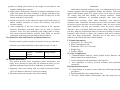
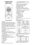
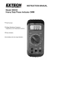
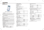
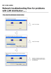
200A Battery Internal Resistance Tester
User’s Manual
position of sliding plate based on the length of test batteries and
retighten sliding plate setscrew.
4. Align positive and negative electrodes of batteries with those on test
probe, and ensure the center of battery is aligned with that of test
probe and ensure positive/negative electrodes of battery are in full
contact with those of test probe.
5. Switch on power for tester, adjust test range based on the range of
battery internal resistance to ensure test accuracy, and record
accurate reading.
6. After completion of the test, remove batteries in the opposite
direction. Procedures described above can be used as detailed
reference. Also, users may manually push sliding plate to ensure
full contact between batteries and test probe based on specific
production needs and repeat procedures described above.
Test method for lead-acid batteries (or finished batteries)
Properly connect positive/negative electrodes of test pen with those
of batteries (or finished batteries) as described in steps 4, 5 and 5.
200A battery internal resistance tester
Internal
resistance Voltage display
display
Power
Range switch
Test input
IX. Routine maintenance
This section provides basic information about maintenance and
repair. Never attempt to repair this test instrument unless you are
qualified repairman experienced in calibration, test and repair.
1. Regularly clean tester casing with wet cloth and neutral cleaner.
Never use abrasive material or solvent in cleaning.
2. Dirt and moisture on test probe may affect reading.
4
Overview
200A battery internal resistance tester is an instrument used to test
internal resistance and acid membrane damage for batteries. This tester
applies 1KHz digital signal (TTL square wave) to test object to test its
AC voltage drop and thus identify its internal resistance. Unlike
conventional multimeter in operating principle, this tester tests
milliohm-level resistance value while multimeter tests ohm-level
resistance value. In addition, this tester not only can test resistance value
for passive objects but also can test resistance value for active objects
while multimeter can only test resistance value for passive objects.
Therefore, there is dramatic difference between them. With this tester,
you may judge the deteriorated status of batteries according to internal
resistance value. Based on Ohm’s law, batteries with lower resistance
value have better performance. Therefore, use of this tester to test
batteries is the fastest and most reliable method.
I. Technical parameters
1. Input power: AC 220V/110V;
2. Power consumption: 8W;
3. Dimension: 250 x 210 x 70 (mm);
4. Weight: 2kg;
5. Display: Digital
II. Scope of applications
1. Cadmium-lithium batteries, metal hydride nickel batteries and
lithium batteries for mobile phone;
2. Lead-acid batteries and maintenance-free batteries;
3. Also applicable to battery research institutes and production
enterprises.
III. Important instructions
To avoid damage in operation, please follow the following operating
procedures:
1. Read through this user’s manual before use.
2. Test time: About 100ms (milliseconds) after full contact for test
1
terminals.
3. Test frequency: 1KHz ±5% square wave.
4. Maximum voltage to be tested: Below 19.99V.
5. Switch on power, check and ensure test probe socket and test pin
are in proper contact.
6. To avoid short circuit, please avoid contact between two test pins on
the test rack.
7. Never use this tester in environment where flammable substances or
gases exist or temperature/humidity is excessively high.
8. Ensure internal resistance and voltage of test batteries are within the
test range of the tester. Voltage higher than test range (19.99V) may
cause damage to the instrument.
9. If the instrument does not work properly or cannot work, calibrate it
as instructed. If such fault remains unsolved, send it for repair.
IV. Test range and precision
Function
Range
Test
Resolution
Test time
Precision
Input impedance
range
Internal
200mΩ
1-200mΩ
0.1 mΩ
100ms
100ms
-
resistance
2Ω
1m-2Ω
1 mΩ
100ms
100ms
-
Voltage
19.99V
0-19.99V
0.01V
100ms
100ms
10K
Notes:
a. Test time: About 100ms (milliseconds) after full contact four test
terminals.
b. Test frequency: 1KHz ±5% square wave (TTL).
c. Maximum voltage: Below 19.99V (DC).
V. Front panel description
Battery internal resistance tester
Internal resistance display
Voltage display
Power
Range
Test input
①Power switch: (Power On/Off)
②Internal resistance display: Displays internal resistance reading for
test batteries (mΩ and Ω).
2
③ Voltage display: Displays maximum voltage for test batteries
(Maximum voltage: 19.99V).
④ Internal resistance range (unit) switch: Used to switch between
milliohms (mΩ) and ohms (Ω). At mΩ level, maximum internal
resistance for test batteries should not exceed 199.9mΩ. At Ω level,
maximum internal resistance for test batteries should not exceed
1.999Ω.
⑤Test input socket: Used to connect test fixture. Switch off power
before connection.
VI. Test rack
①Rack assembly: Battery test table.
②⑤Test probe fixing rack (Moveable plate): Plates can be moved in
the process of test according to battery length to facilitate test.
③④Electrode thimble: Used to connect battery electrodes. Avoid
short circuit between test probes.
⑥Connector terminal for test input.
VII. Relations between battery internal resistance and voltage (time)
Internal resistance value is used to identify battery performance status.
Relations between battery internal resistance and voltage (or time)
are shown below: (Relational curve between battery internal
resistance and voltage)
Internal resistance
Voltage
Change in time
VIII. Test procedures
Select suitable test rack according to battery types (We may provide
special test racks and test pens to meet customers’ specific needs).
Below is a description about typical methods for use of test racks.
1. Plug test rack terminal into socket on front panel and tighten
screws.
2. Switch on power for the instrument (AC220V/110V).
3. Loosen setscrews at the bottom of test rack sliding plate, adjust the
3
3. To avoid electric shock and damage to the instrument, be sure to
switch off power before replacing fuses.
4. Switch off power before replacing test probes. Avoid plugging test
probe into power socket.
X. Troubleshooting
Displays no reading after switching power on
1. If there is no reading display on display screen, switch off power.
2. Check and ensure power is properly connected with main power
outlet.
3. If power is connected with power socket, ensure power switch on
socket is on.
4. Check and ensure that fuse at the back of the tester is in good
conditions.
5. If the problem remains unsolved, please contact manufacturer for
repair.
6. Reading on display screen keeps bouncing or remains locked.
a. Ensure proper contact between test probe and battery end;
b. Ensure no short circuit exists between two test probes on the
same side.
c. Ensure properly contact and connection between test probe and
test rack.
d. Ensure proper contact between test rack terminal and socket on
front panel.
e. Ensure the internal resistance and voltage for test batteries are
within rated range or reading will remain locked on display
screen.
f. If the problem remains unsolved, please contact dealer or
manufacturer.
5