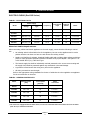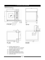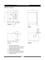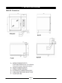
1
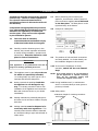
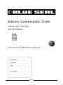
Electric Combination Oven
S Series (Aus / NZ Only)
with Direct Steam
E9CSD
E14CSD
E20CSD
E21CSD
E40CSD
Installation & Maintenance Manual
234861-1
MANUFACTURED BY
Moffat Limited
Christchurch
New Zealand
INTERNATIONAL CONTACTS
AUSTRALIA
Moffat Pty Limited
E.Mail:
Main Office:
Service:
Spares:
Customer Service:
[email protected]
(tel) (03) 9518 3888
(fax) (03 9518 3833
(tel): 1800 622 216
(tel): 1800 337 963
(tel): 1800 335 315
(fax): 1800 350 281
CANADA
Serve Canada
Web:
E.Mail:
Sales:
Service:
www.servecanada.com
[email protected]
(tel): 800 551 8795 (Toll Free)
(tel): 800 263 1455 (Toll Free)
NEW ZEALAND
Moffat Limited
Web:
E.Mail:
Main Office:
www.moffat.co.nz
[email protected]
(tel): 0800 663328
UNITED KINGDOM
Blue Seal
Web:
E.Mail:
Sales:
Spares:
Service:
www.blue-seal.co.uk
[email protected]
(tel): 0121 327 5575
(fax): 0121 327 9711
(tel): 0121 322 6640
(fax): 0121 327 9201
(tel): 0121 322 6644
(fax): 0121 327 6257
UNITED STATES
Moffat
Web:
Sales:
Service:
www.moffat.com
(tel): 800 551 8795 (Toll Free)
(tel): 336 661 1556
(fax): 336 661 9546
(tel): 800 858 4477 (Toll Free)
(tel): 366 661 1556
(fax): 336 661 1660
REST OF WORLD
Moffat Limited
Web:
E.Mail:
www.moffat.co.nz
[email protected]
The reproduction or copying of any part of this manual by any means whatsoever is strictly forbidden unless authorized previously in
writing by the manufacturer.
In line with policy to continually develop and improve its products, Moffat Ltd. reserves the right to change the specifications and
design without prior notice.
© Copyright Moffat Ltd. June 2010.
234861-1
CONTENTS
Page
1.
INTRODUCTION
2
2.
SPECIFICATIONS
4
3.
INSTALLATION DIAGRAMS
5
4.
SPECIAL REQUIREMENTS FOR THE INSTALLATION SITE
11
5.
STATUTORY REQUIREMENTS, TECHNICAL REGULATIONS AND DIRECTIVES
12
6.
POSITIONING
13
7.
ELECTRICAL CONNECTIONS AND EQUIPOTENTIAL BONDING
14
8.
POINTS TO REMEMBER WHEN MAKING THE ELECTRICAL CONNECTION
14
9.
WATER AND DRAIN CONNECTIONS
15
10.
VENTS
18
11.
COMMISSIONING AND TESTING
18
12.
IMPORTANT INFORMATION FOR THE USER
19
NOTES
20
MODELS
ELECTRICAL
E9CSD
E14CSD
E20CSD
E21CSD
E40CSD
VERSIONS
S - Programmable electronics with direct access key to the programs and recipes, automatic humidity
control and lighting.
The manufacturer accepts no liability for any inaccuracies in this manual
attributable to printing or copying errors. We reserve the right to
modify our products as we deem fit, without impairing their basic
features.
The reproduction or copying of any part of this manual by any means
whatsoever is strictly forbidden unless authorized previously in writing
by the manufacturer.
15.09.2008
234861-1
1
1 INTRODUCTION
We are confident that you will be delighted with your Blue Seal Combi Oven, and it will become a most
valued appliance in your commercial kitchen.
To ensure you receive the utmost benefit from your new Blue Seal appliance, there are two important
things you can do.
Firstly
Please read the instruction book carefully and follow the directions given. The time taken will be well
spent.
Secondly
If you are unsure of any aspect of the installation, instructions or performance of your appliance,
contact you BLUE SEAL dealer promptly. In many cases, a phone call could answer your questions.
WARNING:
GREAT CARE MUST BE TAKEN BY THE OPERATOR
TO USE THE EQUIPMENT SAFELY TO GUARD IT AGAINST
RISK OF FIRE.
•
•
THE APPLIANCE MUST NOT BE LEFT ON UNATTENDED.
IT IS RECOMMENDED THAT A REGULAR INSPECTION IS MADE BY A QUALIFIED SERVICE PERSON TO
ENSURE CORRECT AND SAFE OPERATION OF YOUR APPLIANCE IS MAINTAINED.
WARNING:
DO NOT STORE OR USE GASOLINE OR OTHER FLAMMABLE VAPOURS OR LIQUIDS IN THE VICINITY OF THIS
OR ANY OTHER APPLIANCE.
DO NOT SPRAY AEROSOLS IN THE VICINITY OF THIS APPLIANCE WHILE IT IS IN OPERATION.
WARNING:
IMPROPER INSTALLATION, ADJUSTMENT, ALTERATION, SERVICE OR MAINTENANCE CAN CAUSE PROPERTY
DAMAGE, INJURY OR DEATH. READ THE INSTALLATION, OPERATING AND MAINTENANCE INSTRUCTIONS
THOROUGHLY BEFORE INSTALLING OR SERVICING THIS APPLIANCE.
C AUTIO N :
This appliance is for professional use and is only to be used by qualified
people.
234861-1
2
1 INTRODUCTION
Installations must be carried out by qualified
persons only. Failure to install equipment to
the relevant codes and manufacturer’s
specifications shown in this section will void
the warranty.
Components having adjustments protected
(e.g. paint sealed) by manufacturer are only
allowed to be adjusted by an authorised
service agent. They are not to be adjusted
by the installation person.
1.1
The oven must be installed,
commissioned and maintained only by
a Blue Seal authorized service agent.
1.2
Carefully read the directions given in this
manual; they contain important information
on safety during installation, operation and
maintenance. Keep this manual in a safe
place for future consultation!
1.7
Before positioning and connecting the
appliance, check that the utilities (electrical
power and water supplies) are as indicated
on the data plate. The data plate is on the
right-hand side, at the bottom.
1.8
Example of a data plate:-
1.9
The positions of inlet and drain connections
are clearly labelled. For further details, see
the installation diagram in this manual.
C AUTIO N :
1.10 In the event of breakdown or faulty
operation, switch ‘Off’ the oven immediately!
This appliance is for professional use and is
only to be used by qualified personnel.
1.3
This appliance must be put only to the use
for which it is specifically intended,
i.e. cooking foods; any other type of use is
improper and therefore dangerous.
1.4
Having removed the packing check that
the appliance is not damaged in any
way. If in doubt, proceed no further with
installation of the appliance and contact the
Blue Seal Customer Service or your dealer
immediately.
NOTE: If for some reason it is not possible to
get the appliance to operate correctly,
shut off the electrical supply and
contact the supplier of this unit.
1.11 During installation and / or maintenance
work it is recommended you wear gloves to
protect your hands.
1.12 Safety sticker.
1.5
Packing materials are potentially dangerous
and must not be left where children can play
with them.
1.6
Packing materials must be disposed of in
conformity with local regulations. This
normally means that the different materials
are sorted according to type and collected as
urban refuse.
• Maximum height for inserting containers
with liquids.
234861-1
3
2 SPECIFICATIONS
ELECTRIC OVENS (ExxCSD Series)
TABLE 1: ELECTRICAL DATA
Power Supply
Frequency
Total Power
Input
Amps @
400Vac
Motor
3P+N+E
50 Hz
9.5 kW
14
1 x 0.25 kW
400-415 V ac
3P+N+E
50 Hz
16 kW
23
1 x 0.55 kW
E20CSD
400-415 V ac
3P+N+E
50 Hz
31 kW
45
1 x 0.55 kW
E21CSD
400-415 V ac
3P+N+E
50 Hz
31.8 kW
46
2 x 0.55 kW
E40CSD
400-415 V ac
3P+N+E
50 Hz
61.8 kW
89
2 x 0.55 kW
Model
E9CSD
E14CSD
Voltage
Type
400-415 V ac
Electrical Cable Requirements
When connecting a Blue Seal electric appliance to the main supply, ensure that the following is carried
out:• An isolating switch is fitted within 2m of the appliance, but not on the appliance and in such a
position that the user does not have to reach across the cooking surface.
•
Supply cord shall be oil-resistant, sheathed flexible cable and not lighter than ordinary polychloroprene or other equivalent synthetic elastomer sheathed cord (as per AS/NZS 3191 part 2.10.11.
or IEC 60245-IEC-57) e.g. H05 RN-F Type.
•
The branch supply line shall be individually overload protected to the correct current rating and
the supply chord shall be protected against any mechanical or thermal damage.
•
A grommet is fitted around the wiring entry hole into the appliance.
•
All wiring connections must be tight.
Refer to the appropriate wiring standards for the size of cable that is to be supplied to an appliance
for the current drawn on that line.
TABLE 2: GENERAL WATER DATA
Water Pressure
[kPa]
Softened Water
Consumption
[max.l/h]
Water
Connection
200 - 500
15
2 x R 3/4" (1)
200 - 500
22
2 x R 3/4" (1)
E20CSD
200 - 500
22
2 x R 3/4" (1)
E21CSD
200 - 500
30
2 x R 3/4" (1)
E40CSD
200 - 500
44
2 x R 3/4" (1)
Model
E9CSD
E14CSD
(1)
The ovens are equipped with two water inlets, one for non-softened cold water and the other for hot water
(max. 50 °C) or softened cold water.
234861-1
4
3. INSTALLATION DIAGRAMS
E9CSD- Dimensions
234861-1
5
3. INSTALLATION DIAGRAMS
E14CSD - Dimensions
234861-1
6
3. INSTALLATION DIAGRAMS
E20CSD - Dimensions
3 INSTALLATION DIAGRAMS
234861-1
7
3. INSTALLATION DIAGRAMS
E21CSD - Dimensions
234861-1
8
3. INSTALLATION DIAGRAMS
E40CSD - Dimensions
234861-1
9
3 INSTALLATION DIAGRAMS
DISTANCES TO OBSERVE
We recommend keeping a distance of 500mm
on the right-hand side in order to carry out
maintenance work.
DO NOT INSTALL APPLIANCES WITH
A SOURCE OF HEAT ON THE RIGHTHAND SIDE OF THE OVEN
C AUTIO N :
If the ambient temperature to the
right of the appliance is too high, the
oven will stop for safety reasons.
Minimum distance from sources of heat on
the right-hand side: 400mm.
234861-1
10
4 SPECIAL REQUIREMENTS FOR THE INSTALLATION SITE
Installation Requirements
NOTE:
• It is most important that this appliance is installed correctly and that operation is
correct before use. Installation shall comply with local electrical and health and
safety requirements.
• This appliance shall be installed with sufficient ventilation to prevent the occurrence
of unacceptable concentrations of health harmful substances in the room, the
appliance is installed in.
This appliance is designed to provide years of satisfactory service, and correct installation is essential to
achieve the best performance, efficiency and trouble-free operation.
It must be installed in accordance with applicable National and Local installation, electrical and fire safety
codes.
Australia / New Zealand
AS/NZS3000
- Wiring Rules.
AS/NZS3500
- Plumbing and Drainage Code.
Installations must be carried out by authorised persons only. Failure to install equipment to the
relevant codes and manufacturer’s specifications shown in this section will void the warranty.
Components having adjustments protected (e.g. paint sealed) by manufacturer are only allowed to
be adjusted by an authorised service agent. They are not to be adjusted by the installation person.
The manufacturer accepts no liability for any damage or malfunctioning of the appliance
attributable to the absence or inadequacy of earthing systems, to the incorrect arrangement or
installation of auxiliary systems, also to incorrectly made connections or to non-compliance of the
building's electrical system with current regulations.
4.1
The room where the oven is to be fitted has
to be well ventilated (see specific
regulations).
4.2
In addition, it is good policy to locate the
appliance under an extractor hood so that
cooking vapours can be removed rapidly and
continuously.
4.3
4.4
pressure specifications (See Section 2
'Specifications' and Section 9 'Water
and Drain Connections'). A shutoff valve
must be installed on each of the oven water
supply pipelines to the appliance.
Current electrical safety regulations require
the installation of a multiple pole switch
between the oven and the electrical power
supply; the switch must have a contact gap
of at least 3mm on each pole.
4.5
The room must have a water drain in a good
position for the oven to be installed, its
specifications are given under Section 9
'Water and Drain Connections' in this
manual.
4.6
The electrical isolating switch and the water
shutoff valves must all be located near to the
appliance, within easy reach for the user.
The oven needs two water supplies, one of
which need not be softened, but must be
cold (for condensing steam). The other
supply, serving the vaporizer, must
incorporate a softener with suitable flow and
234861-1
11
5 STATUTORY REQUIREMENTS, TECHNICAL REGULATIONS AND DIRECTIVES
Throughout installation it is vital to observe the
following requirements:
5.4
Current requirements relating to electrical
systems.
5.1
Any health and hygiene standards applicable
to kitchens and eating places;
5.5
The regulations of the electrical power
supply company or agency;
5.2
Local and/or territorial building regulations
and fire prevention standards;
5.6
Any other local regulations.
5.3
Current accident prevention guidelines;
6 POSITIONING
6.1
To position the appliances, it is
recommended to use the mount offered by
the manufacturer; should you want to do
things differently, it is necessary to take
account of the weight of the appliance.
6.2
Before manoeuvring the oven into the
selected position, attach the water inlet
hoses and waste pipe to the relative
connection points (See Section 9 'Water
and Drain Connections').
6.3
The distances from other appliances or from
adjacent walls that must be left to allow
access for servicing operations will be found
on the installation diagram for the oven to
connect. In the event of the oven being
installed directly against an inflammable
wall, suitable heat insulation must be
provided. Current fire regulations should be
meticulously observed and respected. Do
not obstruct the openings and slots in the
casing as they disperse the heat in the
electric component compartment.
Keep strictly to the installation diagrams.
6.4
Once the appliance is installed, the
electrical power cable must be protected,
and never stretched or tugged.
6.5
The appliance must be level: any difference
in level or sloping of the supporting surface
should be eliminated. Differences in level or
sloping negatively affect oven operation.
234861-1
12
6 POSITIONING
6.6
Remove all packing materials and peel away
the protective plastic film from all external
surfaces of the oven.
6.7
For free-standing models, the appliance
needs to be levelled: small differences in
level of the supporting surface can be
eliminated with the adjustable feet (by
screwing or unscrewing them).
A significantly uneven or sloping stance can
affect the operation of the oven adversely.
For models equipped with a pan trolley, it is
necessary to pay special attention when
levelling.
6.8
Lining up the pan trolleys 21CSD and
40CSD. If the floor is not level, a
remedy must be found using an access ramp
with a maximum gradient of 4° (not included
in the supply). If there is an outlet grate in
front of the appliance, it is necessary to fit
runners in the pan trolley entry area.
234861-1
13
7 ELECTRICAL CONNECTIONS AND EQUIPOTENTIAL BONDING
7.1
7.2
As this oven is supplied without a power
cable and plug, the cable and other
hardware needed to make the connection to
the electrical power supply must be provided
by the installer. The cable must satisfy the
requirements indicated in Table 1
'Electrical Data'.
The oven must be connected to the power
supply by way of a multiple pole main
isolating switch ensuring a gap between
open contacts of at least 3mm on each pole.
7.3
The cable must be fed in from beneath the
clamp. The individual wires are then
fastened to the corresponding terminals of
the terminal board. The earth wire must be
longer than the other wires, so that in the
event of the cable being jerked or the clamp
broken, the live wires will disconnect first.
Check the efficiency of the isolating switch.
7.4
The oven must be kept in an equipotential
system. This connection is made by wiring a
conductor of nominal cross section 10 mm2
to the corresponding terminal at the back of
the oven, which is marked with the
internationally recognized symbol. All
appliances in the room are bonded in this
way and connected to the earth system of
the building.
7.5
The electrical safety of this appliance can be
guaranteed only when it is connected
correctly to an efficient earth system, in
compliance with current standards.
To gain access to the AC mains connection
terminal board, the right hand panel of the
casing must be removed by undoing the
fixing screws (all models).
8 POINTS TO REMEMBER WHEN MAKING THE ELECTRICAL CONNECTION
8.1
As all ovens of the series are fitted with an
alternating fan motor (clockwise and
anticlockwise rotation), there is no need for
the fan to rotate in any particular direction.
Simply verify, when commissioning the
appliance, that the fan is balanced and
rotates freely.
NOTE:
8.2
8.3
The 21CSD and 40CSD models are
equipped with two motors.
When making the electrical connection, care
is needed to ensure that the neutral pin of
the terminal block corresponds to the
neutral wire of the supply line. If this
connection is not made correctly, the
elements will not operate.
234861-1
14
Check also that the neutral registers zero
potential when tested. If not, the fault
described in Item 8.2 of this section will
occur. If this happens, consult the installer
of the building's electrical system.
9 WATER AND DRAIN CONNECTIONS
Australia / New Zealand only:
Water installation must be done in compliance with
AS/NZS 3500 Plumbing and Drainage Code.
Australia only:
Double Check Valve supplied with this appliance
must be installed in the water supply line to this
appliance to provide total backflow prevention
required by Plumbing Code of Australia.
This valve must be installed on upstream of any
water filtering or conditioning device installed in
association with this appliance, i.e. before the
water supply line separation into the separate inlet
water connections (A) and (B) of this appliance.
9.1
WATER PRESSURE
The pressure of the water in the network
must be between 200 and 500 kPa, as
already stated under Section 2
'Specifications'. If the supply pressure is
higher than this, a pressure reduction valve
must be installed between the oven and the
mains supply.
9.3
9.2
WATER CONNECTIONS
The water supplied must be either cold and
softened or hot (max 50 °C), as described
below.
The water connection is R 3/4”.
The hose for connection to the water supply
must be provided by the installer.
A shutoff valve must be installed on the line
between the oven and the mains supply.
WATER SPECIFICATIONS
The characteristics of the water must come
within the limits given below, in order to
prevent both corrosion, which is extremely
damaging for the appliance, due to
supplying water that is too softened or too
aggressive, and scaling in the oven and in
the water system in the case of supplying
water that is too hard.
Hardness:
PH:
Chlorides:
Between 3° and 6° TH.
Greater than 7.5.
Less than 30 ppm.
These values are important for ensuring that
the water used by the appliance is suitably
treated!
9.4
234861-1
15
WATER CONNECTIONS FOR
CONDENSING STEAM
The water used for condensing steam need
not be softened, but must necessarily be
cold. The water connection is R 3/4.
The hose for connection to the water supply
must be provided by the installer.
A shutoff valve must be installed on the line
between the oven and the supply.
9 WATER AND DRAIN CONNECTIONS
9.5
DRAINING
The water is drained off by gravity through a
heat-resistant pipe DN 50 (not flexible),
maximum length 2m, installed at an angle of
no less than 4°. Mean temperature of the
drain water approx 65 °C.
For the range with the drain as per Fig 1, it is
possible to make a direct connection with an air
trap, without fitting a drain cup, as the drainage
manifold system has an internal air drop (Fig. 2).
With a drain on the floor without an air trap, it is
necessary to have an outlet clearance of 2cm (See
Fig. 3).
For the remaining models, it is imperative to fit a
tundish to ensure a minimum air drop of 25mm.
between the appliance's plastic drain elbow and
drain line. A direct connection is not
permissible.
C AUTIO N :
The drain line must be outside the perimeter of the oven.
reduce the drain diameter.
234861-1
16
It is prohibited to
9 WATER AND DRAIN CONNECTIONS
9.6
FITTING THE HAND SHOWER
NOTE:
To fit the shower attachment, the oven RH
side panel must be removed. Do NOT attempt to fit the hand shower attachment
without removing the side panel as electrical
equipment behind the panel can get
damaged and there is potential for causing
electric shock. Ensure electrical power is
disconnected before commencing.
5. Ensure that the water
supply is turned off at
the mains shut-off
valve.
6. Connect up the hose
connection from the
shower head to the ‘T’
connection at the rear of
the oven.
The oven is supplied with a hand shower
attachment which must be fitted to the oven as part
of the installation process.
NOTE:
Ensure that the supplied sealing washers are
fitted between the ‘Tee’, Hose and Hand
Shower.
To fit the hand shower attachment, the right hand
side panel of the oven must be removed to drill
and attach the hand shower mounting bracket.
To fit the hand shower attachment, carry out the
following operation:1. Remove the 3
screws securing the
right hand side
panel (as viewed
from front of oven).
7. Fit the shower head to
the shower head
mounting bracket.
Oven R/H
Side
8. Turn ‘On’ the water
supply and check for
leaks.
9. Carry out a functional
check of the shower
head.
Remove 3 Screws
60 mm
2. Drill a 5.5 mm hole
in the top left hand
corner of the side
panel as shown on
the diagram below.
Oven R/H
Side
60 mm
Connect Shower Head
Hose Connection Here.
3. Secure the shower head mounting bracket to
the side panel with the bolt, nut and washers
supplied.
Mounting
Reverse Side
of Panel
4. Refit the side panel to the oven and secure with
3 screws.
234861-1
17
Mounting
Shower
10 VENTS
10.1 Under no circumstances must vents A
and B be shut, blocked or ducted into
other pipes.
A - Vent to extract vapours from the oven.
B - Safety vent.
11 COMMISSIONING AND TESTING
11.4 Carefully refit the right-hand side that was
removed for the above work.
11.1 Check the appliance and the entire
installation straight after connecting.
Check in particular:
• That there are no traces of the protective
film on the outside walls and that the oven
is empty;
• All vents are clear;
• The connections are made as required and
instructed in this handbook;
• All the safety requirements of the current
standards, laws and directives are met;
• There is no leakage from the water
connections;
• Water drainage is clear.
11.5 The test report must be completed in full
and submitted to the customer, who should
then sign in acceptance. With effect from
this moment, the appliance is covered
by the manufacturer’s warranty.
11.2 Now proceed to start the oven as directed in
the user manual, checking for the correct
operation of the appliance.
11.3 You should moreover check that the silicone
joints and sleeves of the water circuit (oven
vent, oven outlet, drip tray) do not leak.
234861-1
18
12 IMPORTANT INFORMATION FOR THE USER
12.5 Explain to the user that certain faults in
operation are often due to simple errors or
oversights such as failure to switch on or
connect utilities. Accordingly, kitchen staff
should be trained in such a way that they
can use the appliance confidently and
understand how it operates.
12.1 With the user manual to hand, show the user
the functions, safety devices, appropriate use
and, above all, the time intervals for
servicing the oven. Maintenance operations
include cleaning the burners, inspecting the
oven elements and cleaning the various
ducts and pipes, and this should be carried
out at least once a year. With this in mind,
customers are recommended to sign a
service agreement.
Faults of a recurring or persistent nature
must be investigated by a Blue Seal
authorized Service Agent.
12.2 Ensure the user is fully aware that such
repair and / or maintenance operations
as may become necessary over time
must be carried out only by a Blue Seal
authorized service agent.
12.3 Explain clearly to the user that in the event
of breakdown or faulty operation, all
connected utilities (water and electricity)
should be shut off immediately.
12.4 Keep the installation manual and the wiring
diagram for future reference. Explain to the
user that the user manual supplied with the
oven must be kept near the oven in a place
where it can be seen. It is good policy to
make a note, in the user manual, of the
name and contact numbers of the selected
Service Agent.
234861-1
19
NOTES
234861-1
20