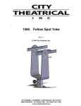
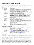
1
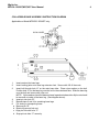
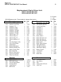
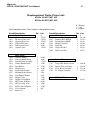
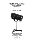
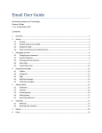
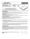
MIGHTY ARC SERIES IIs
HTI 400 WATT FOLLOWSPOT
USER MANUAL
MODELS:
MTA IIs-120/NST
MTA IIs-120/MST
MTA IIs-120/HST
PHOEBUS MANUFACTURING
2800 THIRD STREET
SAN FRANCISCO, CA 94107
U.S.A.
415 550 1177 TEL
415 550 2655 FAX
www.phoebus.com
MIGHTY ARC SERIES IIs
USER MANUAL
MTA IIs-120/NST
MTA IIs-120/MST
MTA IIs-120/HST
January 2002
CONTENTS
PAGE
LIMITED WARRANTY.......................................................................................................2
INITIAL SET-UP AND OPERATION .................................................................................. 3
COLLAPSIBLE BASE ASSEMBLY INSTRUCTION DIAGRAM ........................................4
CONTROL DESCRIPTION ...............................................................................................5
FOLLOWSPOT OPERATION............................................................................................5
OPTICAL SYSTEM OPERATION
I.SET UP AND FOCUSING..........................................................................................6
I.BEAM CONTROL.................. ....................................................................................6
TECHNICAL DATA
I.LAMP ......................... ...............................................................................................7
I.ELECTRICAL .............................................................................................................7
MAINTENANCE
I.LAMP INSTALLATION ...............................................................................................8
II.LAMP POSITIONING DIAGRAM .............................................................................. 8
III.LENS CLEANING ....................................................................................................9
IV.HOUSING REMOVAL AND LUBRICATION.............................................................9
V.TROUBLESHOOTING..............................................................................................9
REPLACEMENT PARTS LIST ...................................................................................... 10-12
WARRANTY CARD ..........................................................................................................13
Mighty Arc
MTA IIs-120/NST,MST,HST User Manual
LIMITED WARRANTY
Thank you for purchasing the Phoebus Manufacturing Mighty Arc Series II/S.
The Phoebus Manufacturing Mighty Arc Series II/S is warranteed against defects in
material and workmanship for a period of one year from date of purchase from Phoebus
Manufacturing. In case of difficulty, contact Phoebus Manufacturing or your dealer for
repair or return instructions. Iris, dowser, and clipper are warranteed for six months
under normal use.
Lamps are excluded from this warranty. This warranty does not apply to mechanical defects
caused by rough handling or to damage caused by improper operation not in accordance
with this manual. Cause of defect is in the sole judgment of Phoebus Manufacturing .a
This warranty is voidable at Phoebus Manufacturing’s option under the following
circumstances:
User makes unauthorized modifications (electrical or mechanical).
The unit is connected to improper voltage supply.
Any other condition occurs which causes catastrophic failure or impairs Phoebus
Manufacturing’s ability to render proper service.
If the unit is modified by the customer without permission, the customer agrees to pay for
any time or parts necessary to remove the modifications before repair, if necessary.
Phoebus will not be responsible for consequential damages caused by failure for whatever
reason of equipment of its manufacture. Sole liability is for equipment of its manufacture.
Sole liability is for repair or replacement (at Phoebus Manufacturing’s option) of the defective equipment under the terms described above.
2
Mighty Arc
MTA IIs-120/NST,MST,HST User Manual
INITIAL SET-UP AND OPERATION
1. Unpack carefully and inspect for shipping damage.
2. Insert casters into the base legs. Position cast legs around end of 1 - 3/4" pipe.
Securewith the hardware provided. Slide height collar onto yoke tube.
Insert yoke tube into base pipe. (See Collapsible Base Assembly Instruction Diagram onpage 4, applicable on Model MTA/2/S-120/HST only).
3. Slide in first the small then the large yoke knob washers onto the threaded stud of thyoke
knob. Thread knob into the bail until it is flushed to the yoke weld nut on the other
side of the bail. Spread washers fully apart so that yoke can be inserted between them.
4. Lift the Mighty Arc Series II/S using the front and rear of the chassis as supports. Position
the bail handle shafts in the U-shaped slots at the top of the yoke. Ensure that the washers
are positioned properly. Turn the tilt lock knobs to tighten the grip on the yoke.
5. Remove shipping screws and washers. Switch screws with the two tapered lens
handles, utilizing washers, thread handles into lens blocks through the slots.
6. Color Gel Insertion:
A. Unscrew four thumbscrews on either side of the color boomerang.
B. Lift boomerang off. Position it upside down, control levers facing you.
C. Raise the left-hand (operator right) gel holder and lower all the others.
D. Use the ring as a pattern to cut gel. Darker gels should be put in left-hand (operator
right) gel holders.
E. Insert gel, cover with ring and secure with three clips.
F. Lower left-hand (operator right) gel holder and raise next one.
G. Repeat steps D to F. To access the bottom gel clip, raise all the gels to the left
or right and lower the one being worked on.
H. As you move toward the right hand gels (operator left), insert progressively lighter
colors. The left-hand (operator right) holder should be used for deep blue or
purple gels. This will prolong their life.
7. Place the color boomerang on the bottom of the Mighty Arc Series II/S with the lever
handles facing the other operating controls. Secure with four thumbscrews near the top of
the boomerang.
8. Insert the three control handles (steel shaft with ball knob) into the slots at the top middle of
Mighty Arc Series II/S. The handles screw into threaded holes which can be seen through
the slots.
9. Remove rear cover. Remove four thumbnuts on rear cover and lift it straight up.
10. Unscrew three thumbscrews on lamp plate. Position lamp (not included) inside ring on
lamp plate. (See diagram on page 8 for correct lamp positioning). Snap fiberglass plate
over base of lamp. Mount lamp plate back onto three posts.
11. Replace rear cover and thumbscrews.
12. Connect to 120 Volt 60Hz power line. Turn power switch to middle position (lamp blower
& gel fan only) be sure both are operating properly, before flipping switch to upper position
to strike lamp. The lamp should strike within 15 seconds and warm up to full output within
60 seconds. If power is interrupted, bulb will go out. Allow 75 seconds for re-strike. Use
middle (fan only) position of power switch before re-strike to cool lamp.
13. Dowser, iris and clipper are controlled by the ball knobs on top.
14. The lens control handle is set for desired throw by sliding it forward for a narrow beam (long
throw) or rearward for a wide beam It may be locked in place by turning it clockwise. Do
not over tighten!
3
Mighty Arc
MTA IIs-120/NST,MST,HST User Manual
COLLAPSIBLE BASE ASSEMBLY INSTRUCTION DIAGRAM
Applicable on Model MTA/2/S-120/HST only.
1.
2.
3.
4.
5.
6.
a.
b.
c.
d.
Insert casters into base legs.
Insert leveling jacks onto base leg extension feet. Secure with 3/8-16 hex nuts.
Insert bolt through hole “A” on the main base tube. Place nylon washer on the bolt.
Position hole “A” on the base leg over the bolt in the main base tube. Slide the base leg
over the bolt and secure with nylon nut.
NOTE: Nylon washer should be between base leg and main base tube. Nylon nut should
be secured on inside of the base leg. (See diagram above).
Insert pin into hole “B”.
Repeat steps 3 and 4 for remaining base legs.
For storing or transporting base:
Remove pin “B”.
Rotate leg around lock nut.
Align pin hole with hole “C”.
Snap pin into hole “C” securely.
4
Mighty Arc
MTA IIs-120/NST,MST,HST User Manual
CONTROL DESCRIPTION
1. POWER SWITCH
2. FUSE
3. LENS CONTROL
4. TILT LOCK KNOB
5. DOWSER
6. CLIPPER
7. IRIS
8. COLOR CONTROLS
FOLLOWSPOT OPERATION
1.
2.
3.
4.
5.
6.
5
Control power to ballast and fans.
Down – Off
Middle – Fans Only
Up – Strike Lamp
3AB 7amp
Changes image size. Turn handle clockwise to lock and
counter-clockwise to unlock. Slide handle forward for
smaller image, spot distribution, long throws. Slide handle
back for larger image, flood distribution, short throws.
Friction lock for vertical tilt of unit.
Mechanical dimmer. Open when lever is moved towards
operator.
Open when lever is moved towards operator. Masks spot
to rectangular strip.
Controls size of image. Opens widest when lever is moved
towards operator. WARNING: Iris left in closed position
withg dowser open for extended time may cause damage
to iris leaves.
Gel is inserted in beam when lever is moved up. Six controls.
Connect to 120 Volt 60Hz power line. Turn power switch to
middle position (lamp blower & gel fan only) be sure both are
operating properly, before flipping switch to upper position to
strike lamp. The lamp should strike within 15 seconds and
warm up to full output within 60 seconds. If power is interrupted, bulb will go out. Allow 75 seconds for re-strike. Use
middle (fan only) position of power switch before re-strike to
cool lamp.
To maximize lamp life turn Power switch to fans only (middle
position) for at least 1 minute after each use.
Dowser, iris and clipper are controlled by the ball knobs on
top.
The front lens control handle (on lower side) is set for desired
throw by sliding it forward for a narrow beam (long throw) or
rearward for a wide beam (short throw). It may be locked in
place by turning it clockwise. Do not over tighten!
The rear lens control handle (side of unit, near middle is
used to obtain the desired focus, soft or hard edge. Slide it
forward for wide beam (short throw) or backward for a narrow
beam (long throw). It may be locked in position by turning
clockwise. Do not over tighten!
To obtain desired throw at a given distance, both lenses must
be moved. Lens position may be chalk marked on the side
Mighty Arc
MTA IIs-120/NST,MST,HST User Manual
OPTICAL SYSTEM OPERATION
I. SET UP AND FOCUSING
1. Turn power switch on (upper position). Lamp should strike within 15 seconds.
Wait 45 seconds for lamp warm-up.
2. Move iris, dowser, and clipper controls to extreme right hand position (viewing the
unit from the rear).
3. Move front lens forward for spot and rear lens rearward for spot distribution and
vice versa for flood distribution. Position can be chalk marked on side of chassis
near handle set.
4. Close down the iris by moving its control handle left.
5. Focus may change slightly with iris closed. Best focus setting is with iris half
open.
II. BEAM CONTROL
1. The dowser is a mechanical dimmer. The rear control handle is moved left to close
and right to open the dowser.
2. The clipper shapes the image to a strip or rectangle of variable height. Move the
middle control handle left to close and right to open the clipper.
3. The iris provides a 6 to 1 change in image diameter. It is controlled by the front
handle, left to close and right to open. The brightest spot is obtained with the iris
open and the lenses adjusted for the largest spot desired. Smaller spots are ob-
6
Mighty Arc
MTA IIs-120/NST,MST,HST User Manual
TECHNICAL DATA
I. LAMP
The Mighty Arc Series II/S uses a Osram HTI 400w/24 lamp or equivalent. This is a 400
watt high luminous vapor discharge lamp utilizing a short light-arc with exactly adjusted
metal halides in the envelope. It is mounted in an integral pre-focused dichroic reflector.
The arc operates at 55 volts. The lamp current is 7.3 amps. A ballast is used to operate
the lamp from standard 120V, 50/60Hz power. Replacement lamps are available from
Osram lamp distributors as well as from Phoebus Manufacturing.
Lamp life is an average of 250 hours in normal use. The life depends on the burning
time per start. Lamps burned for several hours per start will last longer. Operation for
less than 15 minutes per start is not recommended. An hour meter is mounted on the
housing to keep track of lamp life (or rental usage). Lumen loss occurs typically at end
of life and the lamp will fail to start. Another end of life symptom is arc swirl or flicker in
the projected image.
Occasionally, a new lamp may exhibit this problem. Return such to your Osram distributor for exchange.
Color temperature is about 5600° Kelvin (white) but may vary somewhat from lamp to
lamp.
In handling the lamp, avoid touching the quartz arc tube. Use the outside of the reflector or the porcelain base. If the arc tube is touched, clean it with alcohol or freon before
use to prolong lamp life. There is no hazard in handling the lamp, since high pressure is
present only when the bulb is hot. Due to the small arc chamber, these bulbs present no
explosion hazard in contrast to xenon and other high pressure lamps.
The lamp is cooled by a blower located below the lamp. This blower is essential to lamp
operation. Improper cooling will cause decreased life and arc instability or color shift.
The HTI 400w/24 requires a warm up time of 45 seconds to provide full light output. If
power is interrupted while the lamp is running, the arc will extinguish. Avoid hot re-strike.
This will reduce lamp life. Flip the power switch to middle position and allow lamp to cool
before re-striking.
II. ELECTRICAL
The Mighty Arc Series II/S operates on 105 to 125 Volt 50/60 Hz AC. Present models
draw less that 5 amps, starting or running, at high power factor. An electronic ballast is
used to supply the lamp with proper starting and running voltages and currents.
7
Mighty Arc
MTA IIs-120/NST,MST,HST User Manual
MAINTENANCE
I. LAMP INSTALLATION
1. Turn Power Switch to Off position and unplug unit from power source.
2. Remove four thumbscrews on rear housing.
3. Lift rear housing up to remove.
4. Unplug lamp connector.
5. Unsnap fiberglass plate from base of lamp. Do not unhook springs.
6. Lift lamp straight up and out of its holder.
7. Position lamp inside ring on lamp plate. (See diagram below for correct lamp positioning). Snap plate over base of lamp. Mount lamp plate back onto three posts.
8. Plug lamp connector in.
9. Plug the Mighty Arc Series II/S in and turn power switch to on (upper position).
Lamp should strike within 20 seconds and warm up within a minute. Set the lenses
for a narrow spot (long throw position). Observe the distribution of the light across
the area illuminated. The brightest point should be in center. If it is off to one side,
remove rear cover and proceed to adjust the 3 lamp adjustment thumbscrews on
the rear of the lamp bracket, one at a time, to center the pattern. WARNING: Do
not look directly at running lamp. These lamps emit dangerous ultra-violet radiation. We recommend wearing clear or tinted safety goggles when making lamp
adjustments.
10. Replace the rear cover. Replace the four thumbscrews.
NOTE: To prevent lamp breakage during long shipments, removal and separate
packing of the lamp is recommended.
II. LAMP POSITIONING DIAGRAM
8
Mighty Arc
MTA IIs-120/NST,MST,HST User Manual
III. LENS CLEANING
1. Remove front and rear housing to access all lenses for cleaning.
2. Clean all lenses using glass cleaner and a soft, lint-free cloth.
3. To access all surfaces of the dual front lens system, remove the four bolts from
second lens (not mounted to the lens block). Clean first lenses (front and back).
Clean second lens front and back. Replace with the four bolts.
4. Slide rear lens forward and clean both surfaces.
5. Replace front housing and secure with thumbscrews.
6. Replace rear housing and secure with thumbscrews.
IV. HOUSING REMOVAL AND LUBRICATION
1. Remove rear housing (see lamp change procedure).
2. Unscrew the three control handles on top of unit and remove.
3. Unscrew the thumbscrews on the front housing.
4. Tighten vertical tilt lock knobs on either side of yoke (unit will be unbalanced with
housing off).
5. Grip housing at front and rear top edges.
6. Lift straight up until front lens is cleared, and remove.
7. Wipe all four bearing shafts with a clean cloth dampened with light wax or light
lubrication (WD-40). Avoid excess wax.
8. Operate front and rear lenses forward and back to distribute wax.
9. Replace housing, holding front and rear. Guide over lens and line up front of
housing and bulkhead of chassis.
10. Guide rear of housing down and align with thumbscrew pems on the chassis
rails.
11. Replace thumbscrews.
12. Insert and screw in three control handles.
13. Replace rear housing (see lamp change procedure).
14. Tighten all the thumbscrews down.
V. TROUBLESHOOTING – LAMP AND BALLAST (ELECTRICAL)
1. If blower fails to run, check power and fuse. Replace fuse with 7 amp 3AB fuses.
2. If blower runs and lamp does not strike.
A. Check that the lamp connector is firmly seated in its socket. If so, the lamp may
have reached the end of its life. Replace the lamp.
B. If the new lamp does not strike, check line voltages. Lamps may not start with
power line below 105 volts.
C. If the above measures have not been successful, the ballast is probably defective. Call your distributor or Phoebus Manufacturing for further assistance.
9
Mighty Arc
MTA IIs-120/NST,MST,HST User Manual
10
Replacement Parts Price List:
MTA IIs-120 NST, MST, HST
MTA IIs-220 NST, MST, HST
$30.00 Minimum order. Prices subject to change without notice.
Stock# Description
External Parts
3000 Chassis
3001 Housing
3002 Rear Housing
3003 Front Bulkhead
3004 Rear Bulkhead
3005 Guide Handles
3006 Bail
3007 Ballast Cover
3008 Ballast Stand-off (long)
3009 Ballast Stand-off (Short)
3010 Switch Guard
3011 Base legs Medium Duty
3012 Insert Tube Medium Duty
3013 Base Tube Heavy Duty
3014 Base Leg Heavy Duty
3015 Yoke
3100
3101
3102
3103
3104
3105
3106
3107
3108
3109
3110
Internal Parts
Lamp Bracket
Lamp Adjustment Plate
Lamp air Deflector
Lamp Holder Plate
Lamp Holder ring
Lamp Spring Anchor
Lamp Mount Spring
Lamp Adjustment Washer
Dowser Plate
Lower Dowser Jaw
Upper Dowser Jaw
Set
1
1
1
1
1
2
1
1
2
2
1
3
1
1
4
1
List
$
306.00
224.00
65.00
152.00
165.00
89.00
59.00
170.00
29.00
29.00
18.00
139.00
41.00
135.00
246.00
186.00
1
1
1
1
1
4
3
3
1
1
1
91.00
34.00
19.00
33.00
13.00
28.00
8.00
3.00
35.00
33.00
33.00
D = Dowser
I = Iris
C = Clipper
Stock#Description
Set
Internal Parts Cont.
3111 Iris Clipper Bracket
1
3112 Lower Clipper Jaw
1
3114 Upper Clipper Jaw
1
3115 D/C Swivel
1
3116 D/C Swivel Washer
1
3117 D/C Connecting Rod
2
3118 D/C Spacer Bar
2
3119 D/C Slide Retainer
2
3120 Front lens Bracket
1
3121 Front lens Plate
1
3122 Rear Lens Bracket
1
3123 Front Lens Block
1
3124 Rear Lens Block
1
3125 Front & Rear Rail Bracket
2
3126 Iris Mount Clip
3
3127 Front & Rear Lens Bearing 4
3128 Lens Rod
2
3129 Front Lens Washer
8
3130 Clipper lens Frame Mt. plate
1
3131 Clipper lens Mount Frame
2
3132 Relay Lens Plate
1
3133 Light Shield
1
3134 Rear Lens Clips
4
3135 Light Shield Stand-off
4
3136 Lamp Seat
1
3137 Ballast Fan Bracket
1
3138 Lamp Socket Holder
1
3139 Rubber Light baffle
1
3140 Ballast Chassis
1
3141 Exhaust Screen Guard
1
3142 Intake Screen Grard
1
3143 Housing guard
1
List
$
87.00
34.00
34.00
28.00
3.00
30.00
23.00
23.00
65.00
51.00
45.00
54.00
54.00
44.00
13.00
35.00
49.00
14.00
17.00
19.00
17.00
20.00
8.00
13.00
12.00
18.00
12.00
3.00
52.00
11.00
4.00
5.00
Mighty Arc
MTA IIs-120/NST,MST,HST User Manual
11
Replacement Parts Price List:
MTA IIs-120 NST, MST, HST
MTA IIs-220 NST, MST, HST
D = Dowser
I = Iris
C = Clipper
$30.00 Minimum order. Prices subject to change without notice.
Stock# Description
Set
Internal Parts Continued
3144 Aspheric Lens Plate
1
3145 Standoff .375
4
3146 Standoff 1.0 D/F
4
3147 Standoff 2.0 M/F
4
3148 Standoff 1.250 M/F
4
3149 Standoff 1.850 D/F
4
3150 Standoff 3.375 D/F
4
3151 Chassis Plug 7/16"
2
3152 Chassis Plug 3/4"
3
3153 Chassis Plug 5/8"
2
3154 Chassis Bushing 3/4"
1
3155 Iris
1
3156 Lens Rod Brake Collar
4
3157 Lens collar Washer
2
3158 Strain Relief
1
3159 Knurled Thumbnut
3
3160 Knurled Thumbscrew
3
3161 Intake Cooling Tube
1
3162 Blower Bracket
1
3163 Blower Tube Gasket
1
3164 Nylon Lens Washer
9
3165 Front Lens Washer
8
3300
3301
3302
3303
3304
3305
Electrical
HTI 400W Ballast
HTI 400W Lamp
Gossen Strike Button
Terminal Block
Lamp Blower
Ballast Fan
1
1
1
1
1
1
List
$
33.00
6.00
6.00
10.00
10.00
10.00
19.00
2.00
3.00
2.00
1.00
165.00
12.00
4.00
2.00
5.00
5.00
12.00
18.00
7.00
2.00
2.00
1300.00
453.00
41.00
17.00
123.00
79.00
Stock#Description
Set
Automatic Color Boom
3200 Auto Boom Housing
1
3201 Color Frame Ring
6
3201 Gel Frame 1
1
3203 Gel Frame 2
1
3204 Gel Frame 3
1
3205 Gel Frame 4
1
3206 Gel Frame 5
1
3207 Gel Frame 6
1
3208 Boom Striker
6
3209 Boom Release Lever
1
3240 Boom Bracket Left
1
3241 Boom Bracket Right
1
3242 Boom Latch
1
3243 Boom Thrust Washer
7
3244 Spring Rod Block
2
3245 Long Boom Spring
6
3246 Short Boom Spring
1
3247 Boom Cushion
1
3248 Color Brads
18
3249 Color Gel
6
3250 Boom Rod
4
3306
3307
3308
3309
3310
Electrical
3-Position Switch
Fuse Holder
Fuse
Lamp Socket W/leads
Line Cord
1
1
5
1
1
List
$
198.00
75.00
34.00
34.00
34.00
34.00
34.00
34.00
46.00
19.00
21.00
19.00
33.00
54.00
19.00
14.00
5.00
11.00
8.00
25.00
48.00
20.00
9.00
16.00
36.00
35.00
Mighty Arc
MTA IIs-120/NST,MST,HST User Manual
12
Replacement Parts Price List:
MTA IIs-120 NST, MST, HST
MTA IIs-220 NST, MST, HST
$30.00 Minimum order. Prices subject to change without notice.
Stock# Description
Optical
3400 Miniscus Front Lens
3401 Biconvex Front Lens
3402 Negative Rear Lens
3403 Clipper Field Lens
3404 Dowser Field Lens
3405 Aspheric Lens
3500
3501
3700
3503
3504
3505
3506
3507
3508
3509
3510
3511
3512
3513
3514
3515
MISC Parts
Yoke tilt Handle
Yoke tilt Handle Knob
Portable Base Assembly
Control Handle Knob
Lens Handle
Thumbscrew
Small brake Washer
Medium Brake Washer
Lens Handle Washer
Height Collar
Height Collar Handle
HST Caster W/Brake
HST Leveling Jacks
MST Caster W/Brakes
Userʼs Manual
Road Case
Set
1
1
1
1
1
1
List
$
325.00
325.00
152.00
88.00
88.00
123.00
2
4
1
3
2
14
2
2
2
1
1
4
4
3
1
1
60.00
16.00
774.00
15.00
15.00
10.00
4.00
5.00
4.00
31.00
18.00
80.00
34.00
54.00
N/C
*
D = Dowser
I = Iris
C = Clipper
Stock#Description
Set List
Kits
$
3600 Standard Hvy Dty Base Kit 1 643.00
3601 Standard Base HDWE
1 35.00
3602 Portable Base HDWE
1 60.00
3603 Height Collar Kit
1 44.00
3604 Label Kit
1 48.00
3605 Clipper Jaw Kit
1 58.00
3606 Dowser Jaw Kit
1 58.00
Assemblies
3701
3702
3703
3704
Lamp ADJ. Blower Assem
Dowser Plate Assembly
Color Boom Assembly
Iris Clipper Assembly
1
1
1
1
448.00
254.00
573.00
557.00
3800
220 Volt Option
220 Volt Transformer
1
45.00
Mighty Arc
MTA IIs-120/NST,MST,HST User Manual
13
WARRANTY CARD
Please Print
MODEL NUMBER(S)
SERIAL NUMBER(S)
DATE OF PURCHASE
PLACE OF PURCHASE
(DEALER NAME)
USER’S NAME
COMPANY NAME
STREET ADDRESS
CITY / STATE / ZIP
TELEPHONE
FAX
Please fold along the dotted lines and staple
with return address on the outside as shown above.
Thank you!
Place
Stamp
Here
PHOEBUS MANUFACTURING
2800 THIRD STREET
SAN FRANCISCO, CA 94107
ATTENTION: WARRANTY DEPARTMENT