1
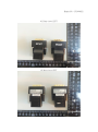
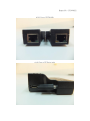
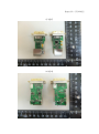
PEP Certification Corp. Date of Issue: Sep. 11, 2013 Report No. : F13090242 FCC 47 CFR PART 15 SUBPART B TEST REPORT FOR DVI CAT5 Extender Model : DE0XXXX (X=0~9,A~Z or Space) Issued to Smart Cabling & Transmission Corp. 10F, No.493, Chung-Cheng Rd., Hsin Tien Dist., New Taipei City 231, Taiwan, R.O.C.Taipei City 105, Taiwan. Issued by PEP Certification Corp. Open Site EMC Test Site Xizhi Office and Lab No. 120, Ln. 5, Hudong St., Xizhi Dist., New Taipei City 221, Taiwan (R.O.C.) 12F.-3, No.27-1, Ln. 169, Kangning St., Xizhi Dist., New Taipei City 221, Taiwan (R.O.C.) Note: This test refers exclusively to the test presented test model and sample. This report shall not be reproduced except in full, without the written approval of PEP Certification Corp. This document may be altered or revised by PEP Certification Corp. Personnel only, and shall be noted in the revision section of the document. Page 1/17 PEP Certification Corp. Date of Issue: Sep. 11, 2013 Report No. : F13090242 TABLE OF CONTENTS -------------------------------------------------------------------------------------------------------- 2 1. GENERAL INFORMATION --------------------------------------------------------------------------------------------------- 3 1.1 DESCRIPTION OF THE TESTED SAMPLES -------------------------------------------------------------------------------------- 4 1.2 TEST RESULT --------------------------------------------------------------------------------------------------------------- 4 1.3 TEST METHODOLOGY ------------------------------------------------------------------------------------------------------------ 5 1.4 DESCRIPTION OF THE SUPPORT EQUIPMENTS ------------------------------------------------------------------- 6 1.5 FEATURES OF EUT: PLEASE REFER TO USER MANUAL OR PRODUCT SPECIFICATION. ----------------------- 6 2. INSTRUMENT AND CALIBRATION---------------------------------------------------------------------------------------- 7 2.1 2.2 2.3 2.4 3. CONDUCTED EMISSION MEASUREMENT --------------------------------------------------------------------------- 12 3.1 3.2 3.3 3.4 3.5 3.6 4. MEASURING INSTRUMENT CALIBRATION ---------------------------------------------------------------------------------- 7 TEST AND MEASUREMENT EQUIPMENT ----------------------------------------------------------------------------------- 7 TEST PERFORMED ---------------------------------------------------------------------------------------------------------- 8 APPENDIX --------------------------------------------------------------------------------------------------------------------- 9 TEST SET-UP (PLEASE REFER TO APPENDIX 1) ----------------------------------------------------------------------- 12 LIMIT ------------------------------------------------------------------------------------------------------------------------- 12 TEST PROCEDURE -------------------------------------------------------------------------------------------------------- 12 TEST SPECIFICATION ----------------------------------------------------------------------------------------------------- 13 RESULT: PASSED ------------------------------------------------------------------------------------------------------ 13 TEST DATA: ---------------------------------------------------------------------------------------------------------------- 13 RADIATED EMISSION MEASUREMENT ------------------------------------------------------------------------------- 14 4.1 4.2 4.3 4.4 4.5 4.6 TEST SETUP (PLEASE REFER TO APPENDIX 1) ------------------------------------------------------------------------ 14 LIMIT ------------------------------------------------------------------------------------------------------------------------- 15 TEST PROCEDURE -------------------------------------------------------------------------------------------------------- 15 TEST SPECIFICATION ----------------------------------------------------------------------------------------------------- 15 RESULT: PASSED -------------------------------------------------------------------------------------------------------- 15 TEST DATA: ---------------------------------------------------------------------------------------------------------------- 15 5. MEASUREMENT UNCERTAINTY ------------------------------------------------------------------------------------------- 16 APPENDIX 1 PHOTOS OF TEST CONFIGURATION APPENDIX 2 TEST DATA PHOTOS OF EUT Page 2/17 PEP Certification Corp. 1. Date of Issue: Sep. 11, 2013 Report No. : F13090242 GENERAL INFORMATION Applicant : Smart Cabling & Transmission Corp. Address : 10F, No.493, Chung-Cheng Rd., Hsin Tien Dist., New Taipei City 231, Taiwan, R.O.C.Taipei City 105, Taiwan. Manufacturer : Smart Cabling & Transmission Corp. Address : 10F, No.493, Chung-Cheng Rd., Hsin Tien Dist., New Taipei City 231, Taiwan, R.O.C.Taipei City 105, Taiwan. EUT : DVI CAT5 Extender Model Name : DE0XXXX (X=0~9,A~Z or Space) Model Differences : N/A Is herewith confirmed to comply with the requirements set out in the FCC Rules and Regulations Part 15 Subpart B and CISPR PUB. 22 and the measurement procedures were according to ANSI C63.4-2003. The said equipment in the configuration described in this report shows the maximum emission levels emanating from equipment are within the compliance requirements. FCC part 15 subpart B Receipt Date : 08/28/2013 Class B Final Test Date : 09/11/2013 Tested By: Sep. 11, 2013 Date Reviewed by: Benny Liu / Engineer Sep. 11, 2013 Date Alex Chou / Manager Designation Number: TW1075 Page 3/17 PEP Certification Corp. Date of Issue: Sep. 11, 2013 Report No. : F13090242 1.1 DESCRIPTION OF THE TESTED SAMPLES EUT EUT Type : Engineer Type Condition when received : Good Damage : EUT Name : DVI CAT5 Extender Model Number : DE0 Receipt Date : 08/28/2013 EUT Power Rating : □ AC Power □ DC Power DCV from PC □ DCV from Adaptor I/O Port of EUT : RJ45 x2 Mini USB x 1 1.2 TEST RESULT Emission Test Standard Test Item Test Result FCC Part 15B Class B Conducted Emission Pass FCC Part 15B Class B Radiated Emission Pass Page 4/17 PEP Certification Corp. Date of Issue: Sep. 11, 2013 Report No. : F13090242 1.3 TEST METHODOLOGY EUT SYSTEM OPERATION 1. The EUT was configured according to ANSI C63.4 – 2003 Section 5.2, 7.1, 7.2 & FCC PART 15B. 2. Photos of test configuration please refer to appendix 1. 3. Perform the EMC testing procedures, and measure the maximum emission noise. Page 5/17 PEP Certification Corp. Date of Issue: Sep. 11, 2013 Report No. : F13090242 1.4 DESCRIPTION OF THE SUPPORT EQUIPMENTS U Setup Diagram See test photographs attached in appendix I for the actual connections between EUT and support equipment. U Support Equipment Peripherals Devices: No. Equipment Model OUTSIDE SUPPORT EQUIPMENT FCC ID/ Serial No. Trade name BSMI ID 1. PC 8985 L3C8543 R33B65 Lenovo 2. Monitor P243WA N/A R3A002 Acer 3. Printer D4360 N/A R33001 HP 4. USB Flash TS2GJFV30 156511-6400 D33193 TRANSCEND 5. Mouse N889 N/A R41101 DELL 6. Keyboard SK-8185 N/A T3A002 DELL 7. Adaptor BLC06-050100 MV N/A N/A N/A Data Cable N/A Shielded 1.8m Shielded 1.8m Shielded 1m Shielded 1.8m / USB Shielded 1.8m / USB N/A Power Cord Unshielded 1.8m Unshielded 1.8m Unshielded 1.8m N/A N/A N/A Unshielded 1.8m Note: All the above equipment /cable were placed in worse case position to maximize emission signals during emission test. Grounding: Grounding was in accordance with the manufacturer’s requirement and conditions for the intended use. 1.5 FEATURES OF EUT: PLEASE REFER TO USER MANUAL OR PRODUCT SPECIFICATION. Page 6/17 PEP Certification Corp. Date of Issue: Sep. 11, 2013 Report No. : F13090242 INSTRUMENT AND CALIBRATION 2. 2.1 MEASURING INSTRUMENT CALIBRATION The measuring equipment utilized to perform the tests documented in the report has been calibrated once a year or in accordance with the manufacturer’s recommendations, and is traceable to recognized national standards. 2.2 TEST AND MEASUREMENT EQUIPMENT The following list contains measurement equipment used for testing. The equipment conforms to the requirement of CISPR 16-1, ANSI C63.2 and. Other required standards. Calibration of all test and measurement, including any accessories that may effect such calibration, is checked frequently to ensure the accuracy. Adjustments are made and correction factors are applied in accordance with the instructions contained in the respective. TABLELIST OF TEST AND MEASUREMENT EQUIPMENT Test Site Instrument Manufacturer Model No. S/N Next Cal. Date Receiver R&S ESHS10 830223/008 Nov. 23, 2014 Spectrum Analyzer ADVANTEST R3261C 87120343 Mar. 18, 2014 RF Cable MIYAZAKI & Anritsu RG58A0 & MP59B M79094 Apr. 08, 2014 NNB-2/16z 98062 Jan. 16, 2014 Conduction L.I.S.N Radiation Rolf Heine Hochfrequenztechnik EMI Test Receiver R&S EAHS-10 1093.4495.03 Mar. 21, 2014 Click Analyzer Schaffner DIA1512C 5218 June 15, 2014 Spectrum Analyzer Nex1 NS-265 NO5044006 Aug. 04, 2014 Antenna Schwarzbeck VULB 9161 4077 Feb. 02, 2014 RF Cable N/A N/A N/A Jan. 18, 2014 Pre-Amp Schaffner CPA-9232 1012 Jan. 20, 2014 CALIBRATION INTERVAL OF INSTRUMENTS LISTED ABOVE IS ONE YEAR Page 7/17 PEP Certification Corp. 2.3 Date of Issue: Sep. 11, 2013 Report No. : F13090242 TEST PERFORMED Conducted emissions were invested over the frequency range from 0.15MHz to 30MHz using a receiver which bandwidth is set at 9KHz. Radiated emissions were invested over the frequency range from 30MHz to 1000MHz using a receiver which bandwidth is set at 120KHz. Radiated measurement was performed at distance that from an antenna to EUT is 10meters. Page 8/17 PEP Certification Corp. 2.4 Date of Issue: Sep. 11, 2013 Report No. : F13090242 APPENDIX Appendix A: Measurement Procedure for Main Power Port Conducted Emissions The measurements are performed in a PEP lab’s room; The EUT was placed on non-conductive1.0m x 1.5m table, which is 0.8 meters above an earth-grounded. Power to the EUT was provided through the LISN which has the Impedance (50ohm/50uH) vs. Frequency Characteristic in accordance with the standard. Powers to the LISNs were filtered to eliminate ambient signal interference and these filters were bonded to the ground plane. Peripheral equipment required to provide a functional system (support equipment) for EUT testing was powered from the second LISN through a ganged, metal power outlet box which is bonded to the ground plane at the LISN. If the EUT is supplied with a flexible power cord, the power cord length in excess of the distance separating the EUT from the LISN shall be folded back and forth at the center of the lead so as to form a bundle not exceeding 40cm in length. If the EUT is provided with a permanently coiled power cord, bundling of the cord is not required. If the EUT is supplied without a power cord, the EUT shall be connected to the LISN by a power cord of the type specified by the manufacturer which shall not be longer than 1 meter. The excess power cord shall be bundled as described above. If a non-flexible power cord is provided with the EUT, it shall be cut to the length necessary to attach the EUT to the LISN and shall not be bundled. The interconnecting cables were arranged and moved to get the maximum measurement. Both the line of power cord, hot and neutral, were measured. The highest emissions were analyzed in details by operating the spectrum analyzer in fixed tuned mode to determine the nature of the emissions and to provide information which could be useful in reducing their amplitude. Appendix B: Test Procedure for Radiated Emissions Preliminary Measurements in the Anechoic Chamber The radiated emissions are initially measured in the anechoic chamber at a measurement distance of 3 meters. Desktop EUT are placed on a wooden stand 0.8 meter in height. The measurement antenna is 3 meters from the EUT. The test setup in anechoic chamber is the same as open site. The turntable rotated 360. The antenna height is 1m. The primary objective of the radiated measurements in the anechoic chamber is to identify the frequency spectrum in the absence of the electromagnetic environment existing on the open test site. The frequencies can then be pre-selected on the open test site to obtain the corresponding amplitude. The initial scan is made with the spectrum analyzer in automatic sweep mode. The spectrum peaks are then measured manually to determine the exact frequencies. Page 9/17 PEP Certification Corp. Date of Issue: Sep. 11, 2013 Report No. : F13090242 Measurements on the Open Site or Chamber The radiated emissions test will then be repeated on the open site or chamber to measure the amplitudes accurately and without the multiple reflections existing in the shielded room. The EUT and support equipments are set up on the turntable. Desktop EUT are set up on a wooden stand 0.8 meter above the ground. For the initial measurements, the receiving antenna is varied from 1-4 meter height and is changed in the vertical plane from vertical to horizontal polarization at each frequency. Both reading are recorded with the quasi-peak detector with 120KHz bandwidth. For frequency between 30 MHz and 1000MHz, the reading is recorded with peak detector or quasi-peak detector. At the highest amplitudes observed, the EUT is rotated in the horizontal plane while changing the antenna polarization in the vertical plane to maximize the reading. The interconnecting cables were arranged and moved to get the maximum measurement. Once the maximum reading is obtained, the antenna elevation and polarization will be varied between specified limits to maximize the readings. Page 10/17 PEP Certification Corp. Date of Issue: Sep. 11, 2013 Report No. : F13090242 Appendix C: Warning Labels Label Requirements A Class B digital device subject to certification by the FCC shall carry a warning label which includes the following statement: ***WARNING*** This device complies with Part 15 of the FCC Rules. Operation is subject to the following two conditions: (1) this device may not cause harmful interference, and (2) this device must accept any interference received, including interference that may cause undesired operation. Appendix D: Warning Statement Statement Requirements The operator’s manual for a Class A digital device shall contain the following statements or their equivalent: ***WARNING*** This equipment has been tested and found to comply with the limits for a Class A digital device, pursuant to part 15 of the FCC Rules. These limits are designed to provide reasonable protection against harmful interference when the equipment is operated in a commercial environment This equipment generates, uses, and can radiate radio frequency energy and, if not installed and uses in accordance with the instruction manual, may cause harmful interference to radio communications Operation of this equipment in a residential area is likely to cause harmful interference in which case the user will be required to correct the interference at his own expense. Notice: The changes or modifications not expressly approved by the party responsible for compliance could void the user's authority to operate the equivalent. * * * * * * * * * If the EUT was tested with special shielded cables the operator’s manual for such product shall also contain the following statements or their equivalent: Shielded interface cables and/or AC power cord, if any, must be used in order to comply with the emission limits. Page 11/17 Date of Issue: Sep. 11, 2013 Report No. : F13090242 PEP Certification Corp. CONDUCTED EMISSION MEASUREMENT 3. 3.1 TEST SET-UP (PLEASE REFER TO APPENDIX 1) VCP Receiver EUT Load 80cm Non-Conductive Table LISN LISN HCP 3.2 LIMIT 0.15-0.5 CLASS A QP Average dB(uV) dB(uV) 79 dBuV 66 dBuV 66 - 56 dBuV 56 - 46 dBuV 0.5-5.0 73 dBuV 60 dBuV 56 dBuV 46 dBuV 5.0-30.0 73 dBuV 60 dBuV 60 dBuV 50 dBuV Frequency range (MHz) CLASS B QP Average dB(uV) dB(uV) Remark: In the above table, the tighter limit applies at the band edges. 3.3 TEST PROCEDURE The EUT and simulators are connected to the main power through a line impedance stabilization network (LISN). It provides a 50 ohm / 50 H coupling impedance for the measuring equipment. The peripheral devices are also connected to the main power through a LISN that provides a 50 ohm / 50 H coupling impedance with 50 ohm termination. (Please refer to the block diagram of the test setup and photograph.) Both sides of AC line are checked for the maximum conducted emission interference. In order to find the maximum emissions, the relating positions of equipment and all of the interference cables must be changed according to CISPR22 regulation: The measurement procedure on conducted emission interference. Page 12/17 PEP Certification Corp. Date of Issue: Sep. 11, 2013 Report No. : F13090242 The resolution bandwidth of the field strength meter is set at 9KHz 3.4 TEST SPECIFICATION ANSI C63.4 – 2003 Section 5.2, 7.1, 7.2 & FCC PART 15B CLASS B 3.5 RESULT: PASSED 3.6 TEST DATA: Please refer to appendix 2. Page 13/17 PEP Certification Corp. 4. Date of Issue: Sep. 11, 2013 Report No. : F13090242 RADIATED EMISSION MEASUREMENT 4.1 TEST SETUP (PLEASE REFER TO APPENDIX 1) 1-4M Load Active EUT Antenna and turntable distance: 10m or 3 m. Non-Conductive Table 80 cm Metal Full Soldered Ground Plane Remote Controller Printer Control PC Page 14/17 Spectrum Date of Issue: Sep. 11, 2013 Report No. : F13090242 PEP Certification Corp. 4.2 LIMIT Frequency Class A Class B MHz Distance (Meter) Limit dBV/m Distance (Meter) Limit dBV/m 30 ~ 230 10 40 10 30 230 ~ 1000 10 47 10 37 Frequency range GHz Above 1000 Average limit dB(V/m) 54 Peak limit dB(V/m) 74 Remark: In the above table, the tighter limit applies at the band edges 4.3 TEST PROCEDURE The EUT and its simulators are placed on turn table, non-conductive and wooden table, which is 0.8 meter above ground. The turn table rotates 360 degree to determine the position of the maximum emission level. The EUT was positioned such that distance from antenna to the EUT is 10 meters. The antenna is moved up and down between 1 meter to 4 meter to receive the maximum emission level. Both horizontal and vertical polarizations of the antenna are set on measurement. In order to find the maximum emission, all of the interference cables must be manipulated according to CISPR regulation: the test procedure of the radiated emission measurement. The bandwidth set on the field strength is 120 KHz when the frequency range is below 1GHz 4.4 TEST SPECIFICATION ANSI C63.4 – 2003 Section 5.2, 7.1, 7.2 & FCC PART 15B CLASS B 4.5 RESULT: PASSED 4.6 TEST DATA: Please refer to appendix 2. Page 15/17 PEP Certification Corp. Date of Issue: Sep. 11, 2013 Report No. : F13090242 5. MEASUREMENT UNCERTAINTY Measurement Item Measurement Frequency Polarization Uncertainty Conducted Emission 9 kHz ~ 30. MHz LINE/NEUTRAL 1.78 dB 30 MHz ~ 1,000 MHz Vertical / Horizontal 1.96 dB 1,000 MHz ~ 6,000 MHz Vertical / Horizontal 3.0 dB Radiated Emission Page 16/17 PEP Certification Corp. Date of Issue: Sep. 11, 2013 Report No. : F13090242 SAMPLE OF FCC VERIFICATION LABEL 1 This device complies with part 15 of the FCC Rules. Operation is subject to the following two conditions: (1) This device may not cause harmful interference. And (2)this device must accept any interference received, including interference that may cause undesired operation. SAMPLE OF FCC DoC LABEL 2 Trade Name Model Number Page 17/17 Global Certification Corp. Appendix 1 PHOTOS OF TEST CONFIGURATION Report No.:F13090242 01 CE Front View 02 CE Rear View Report No.:F13090242 03 RE Front View 04 RE Rear View Global Certification Corp. Appendix 2 TEST DATA -1- -2- -1- -2- Global Certification Corp. PHOTO OF EUT PHOTOS OF EUT Report No.:F13090242 01 Front view of EUT 02 Rear view of EUT Report No.:F13090242 03 IO Port of EUT(RJ45) 04 IO Port of EUT(mini usb) Report No.:F13090242 05 MB-F 06 MB-R Report No.:F13090242 07 Cable(mini USB) 08 Cable(RJ45)