1
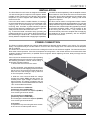
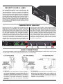
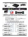
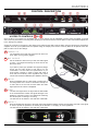
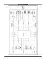
DRAWMER
SL22
Sound Level Limiter
CONTENTS
Warranty . . . . . . . . . . . . . . . . . . . . . . . . . . . . . . . . . . . . . . . . . . . . . . . . . . . . 2
Safety Consideration . . . . . . . . . . . . . . . . . . . . . . . . . . . . . . . . . . . . . . . . . . . 2
Installation . . . . . . . . . . . . . . . . . . . . . . . . . . . . . . . . . . . . . . . . . . . . . . . . . . . 3
Power Connection . . . . . . . . . . . . . . . . . . . . . . . . . . . . . . . . . . . . . . . . . . . . . 3
Chapter 1 - Introduction
Introduction . . . . . . . . . . . . . . . . . . . . . . . . . . . . . . . . . . . . . . . . . . . . . . . . . 4
Security Plate and Label . . . . . . . . . . . . . . . . . . . . . . . . . . . . . . . . . . . . . . . 6
Tamper-proof Bracket . . . . . . . . . . . . . . . . . . . . . . . . . . . . . . . . . . . . . . . . . 6
Audio Connections . . . . . . . . . . . . . . . . . . . . . . . . . . . . . . . . . . . . . . . . . . . 6
Installation and Connection Guide - Stereo Pair . . . . . . . . . . . . . . . . . . . . 7
Installation and Connection Guide - Multiple Speakers . . . . . . . . . . . . . . . . 7
Chapter 2 - Control Description
Control Description . . . . . . . . . . . . . . . . . . . . . . . . . . . . . . . . . . . . . . . . . . . 8
The Setup Procedure . . . . . . . . . . . . . . . . . . . . . . . . . . . . . . . . . . . . . . . . 10
Chapter 3 - General Information
If a fault develops . . . . . . . . . . . . . . . . . . . . . . . . . . . . . . . . . . . . . . . . . . . .12
Contacting Drawmer . . . . . . . . . . . . . . . . . . . . . . . . . . . . . . . . . . . . . . . . . .12
Specification . . . . . . . . . . . . . . . . . . . . . . . . . . . . . . . . . . . . . . . . . . . . . . . .12
Block Diagram. . . . . . . . . . . . . . . . . . . . . . . . . . . . . . . . . . . . . . . . . . . . . . .13
COPYRIGHT
This manual is copyrighted 2015 by Drawmer Electronics Ltd. With all rights reserved. Under copyright
laws, no part of this publication may be reproduced, transmitted, stored in a retrieval system or translated
into any language in any form by any means, mechanical, optical, electronic, recording, or otherwise,
without the written permission of Drawmer Electronics Ltd.
ONE YEAR LIMITED WARRANTY
Drawmer Electronics Ltd., warrants the Drawmer SL22
Sound Level Limiter to conform substantially to the
specifications of this manual for a period of one year from
the original date of purchase when used in accordance with
the specifications detailed in this manual. In the case of a
valid warranty claim, your sole and exclusive remedy and
Drawmer’s entire liability under any theory of liability will be
to, at Drawmer’s discretion, repair or replace the product
without charge, or, if not possible, to refund the purchase
price to you. This warranty is not transferable. It applies only
to the original purchaser of the product.
DRAWMER
SL22
Sound Level Limiter
SAFETY CONSIDERATIONS
CAUTION - MAINS FUSE
For warranty service please call your local Drawmer dealer.
Alternatively call Drawmer Electronics Ltd. at +44 (0)1709
527574. Then ship the defective product, with transportation
and insurance charges pre-paid, to Drawmer Electronics Ltd.,
Coleman Street, Parkgate, Rotherham, S62 6EL UK. Write
the RA number in large letters in a prominent position on the
shipping box. Enclose your name, address, telephone
number, copy of the original sales invoice and a detailed
description of the problem. Drawmer will not accept
responsibility for loss or damage during transit.
TO REDUCE THE RISK OF FIRE
REPLACE THE MAINS FUSE ONLY WITH
A FUSE THAT CONFORMS TO IEC127-2.
250 VOLT WORKING, TIME DELAY TYPE
AND BODY SIZE OF 20mm x 5mm.
THE MAINS INPUT FUSE MUST BE
RATED AT 230V=T63mA and 115V=T125mA.
This warranty is void if the product has been damaged by
misuse, modification or unauthorised repair.
CAUTION - MAINS CABLE
THIS WARRANTY IS IN LIEU OF ALL WARRANTIES,
WHETHER ORAL OR WRITTEN, EXPRESSED, IMPLIED
OR STATUTORY. DRAWMER MAKES NO OTHER
WARRANTY EITHER EXPRESS OR IMPLIED, INCLUDING,
WITHOUT LIMITATION, ANY IMPLIED WARRANTIES OF
MERCHANTABILITY, FITNESS FOR A PARTICULAR
PURPOSE, OR NON-INFRINGEMENT. PURCHASER’S
SOLE AND EXCLUSIVE REMEDY UNDER THIS
WARRANTY SHALL BE REPAIR OR REPLACEMENT AS
SPECIFIED HEREIN.
IN NO EVENT WILL DRAWMER ELECTRONICS LTD. BE
LIABLE FOR ANY DIRECT, INDIRECT, SPECIAL,
INCIDENTAL OR CONSEQUENTIAL DAMAGES
RESULTING FROM ANY DEFECT IN THE PRODUCT,
INCLUDING LOST PROFITS, DAMAGE TO PROPERTY,
AND, TO THE EXTENT PERMITTED BY LAW, DAMAGE
FOR PERSONAL INJURY, EVEN IF DRAWMER HAS BEEN
ADVISED OF THE POSSIBILITY OF SUCH DAMAGES.
DO NOT ATTEMPT TO CHANGE
OR TAMPER WITH THE
SUPPLIED MAINS CABLE.
CAUTION - SERVICING
DO NOT PERFORM ANY SERVICING.
REFER ALL SERVICING TO QUALIFIED
SERVICE PERSONNEL.
WARNING
TO REDUCE THE RISK OF FIRE OR
ELECTRIC SHOCK DO NOT EXPOSE
THIS EQUIPMENT TO RAIN OR MOISTURE.
Some states and specific countries do not allow the exclusion
of implied warranties or limitations on how long an implied
warranty may last, so the above limitations may not apply to
you. This warranty gives you specific legal rights. You may
have additional rights that vary from state to state, and country
to country.
It is the responsibility of the installer to ensure that the continuous power rating of the speakers is not exceeded, as
Drawmer Electronics Ltd will not accept any responsibility for damage caused by incorrect installation and settings.
In the interests of product development, Drawmer reserve the right to modify or improve specifications of this product at any time, without prior notice.
2
CHAPTER 1
INSTALLATION
The SL22 Sound Level Limiter is designed for standard
19" rack mounting and occupies 1U of rack space. Where
possible, avoid mounting the unit directly above power
amplifiers or power supplies that radiate significant
amounts of heat.
If the unit is to be used in a mobile situation, it is strongly
recommended that the rear of the unit is supported in the
carrying rack to avoid bending the front panel rack
mounting ‘ears’. Use fibre or plastic washers to prevent
the front panel becoming marked by the mounting bolts.
Always connect the mains earth to the unit.
Fig. 2 shows the ideal connection setup, providing the
greatest protection for your system. Note the position of
the SL22 along the audio chain - it should be connected
directly before the amplifier that is supplying the speakers,
(or before the active speakers), with the amplifier volume
set to maximum. If the SL22 were to be connected earlier
in the chain, prior to the pre-amp/mixer for example, then
it would be possible to add gain, sending noise levels
higher than required.
The SL22 can be used in a configuration where a stereo
output is distributed around several speakers. Fig.3 shows
a setup where the signal is distributed into six pairs using
a Drawmer DA6, whilst still providing speaker protection
for all twelve speakers. Again, note the position of the
SL22’s along the audio chain - they should all be
connected directly before the amplifier that is supplying
the speakers (or active speakers), with the amplifier
volume set to maximum.
POWER CONNECTION
The SL22 unit will be supplied with a power cable suitable for domestic power outlets in your country. For your own
safety, it is important that you use this cable to connect to the mains supply earth. The cable must not be tampered
with or modified.
The SL22 has an internal fuse to suit the mains voltage for which the unit has been supplied. The fuse should never
blow under normal operation. If the fuse is suspected of having blown, then a fault will have occurred and this fault
condition should be inspected by a qualified service engineer. When replacing the fuse, always comply with the
Safety Instructions.
If the unit is to be used with a mains input operating
voltage different to that for which the unit is supplied,
the following procedure must be carried out by a
technically competent person:
1: Disconnect the unit from the mains.
2: Using a number 1 size pozidrive screwdriver,
remove the seven self-tapping screws that retain
the top cover. Two screws are found along each
side, two at the rear along the top lip, and one
on the front panel, centre top.
3: With the cover removed slide the voltage
change-over switch (VS1) until the correct (or
nearest) mains input voltage is visible on the
switch actuator. The switch is located to the top
right of the main circuit board between the mains
I.E.C. and toroidal transformer.
For conversion to 115Volt AC
(previously set to 230Volt AC).....
4a: Exchange the 63mA fuse adjacent (FUSE1)
for a similar type rated at 125mA
For conversion to 230Volt AC
(previously set to 115Volt AC).....
4b: Exchange the 125mA fuse adjacent (FUSE1)
for a similar type rated at 63mA
In all cases:
5: Replace the top cover using the seven screws.
6: Re-connect to mains power source.
3
DRAWMER
SL22
SOUND LEVEL LIMITER
INTRODUCTION
Safeguard Your Hearing, Protect Your Speakers, and Conform to Regulations!
Whether you need to protect your speakers, your hearing whilst listening to headphones or your premises license the
Drawmer SL22 Sound Level Limiter is the perfect tool for the job. By eliminating the possibility of ’unauthorised’
excessive sound pressure levels it offers strict level control and tremendous peace of mind to users in three distinct
areas:
1
2
3
SAFEGUARD YOUR HEARING
CONFORM TO REGULATIONS
PROTECT YOUR SPEAKERS
Conform to Noise at Work
Regulations by controlling user’s
exposure to audio whilst at work
to help prevent hearing damage
By calibrating and controlling venue
noise levels and in a secure manner
you conform to Local Authority Noise
Regulations
Prevents the damage to speaker
chassis drivers and amplifier electronics by catching unwanted signals
such as ‘bangs’ and ‘pops’
Benefiting from Drawmer’s 30 years involvement in designing industry standard dynamic processing devices, and
especially the experience gained from its sister product, the popular SP2120 Speaker Protector, the SL22 has
been designed to be more versatile and feature rich but at the same time just as easy to set up.
The key features are as follows:
• Limited speaker and headphone outputs.
• Once installed and calibrated completely eliminates the possibility of ’unauthorised’ volume
levels
• No sound quality loss even during protection processing
• Large LED level indication for ’at a glance’ monitoring of signals and warnings
• Time delay relays on outputs for clean power up/down
• Fast, simple installation.
• Tamper-proof plate limits access to settings.
• A security label is supplied to further secure the calibration settings and show evidence of
tampering.
• Tamper-Proof bracket (available separately) to lock-in the XLR’s and conform to Local Authority
regulations.
• Reduces ’call-out’ costs of sound system service/repair engineers, sound system ’down time’
and the consequential loss of venue income, as well as the reputation of the venue.
• External control of Dim and Mute for connection to Fire Alarms or remote operation
• Trigger output when in PROTECT mode
• Logging inputs for both ALERT and PROTECT statuses.
The SL22 front panel features an integral security plate to ensure that adjustments to maximum volume levels are
implemented by authorised personnel only. Once removed two front panel pre-sets are exposed and available for
adjustment by the installer. The first calibrates the protect indication to the incoming audio and dictates the point at
which ’protection’ processing commences. The second sets the absolute volume level to which the sound system is
4
allowed to perform. If the SL22 receives increased signal levels, the transparent ’protection’ circuitry is activated
which maintains the specified system volume level without degradation in sound quality. With the security plate
replaced a security label can be placed across (supplied) to provide further security and show evidence of tampering
with the settings. In addition, on the right side of the panel three LED indicators complement the simple setup with
simple and ‘at a glance’ monitoring.
To the rear the difference between the SL22 and the SP2120 is just as apparent. In its development we liaised with
and were approached by local authority commissioners, installation specialists and venue owners who all advised
and recommended attributes to suit their own specific requirements, the result being the addition many more versatile
features that so many other sound level limiters lack. As well as the standard input and output XLRs (that can be
securely locked using the optional tamperproof bracket) the SL22 also features a limited headphone output, that
works in the same manner as the XLR’s, plus the ability to be controlled externally via a fire alarm or operator, and
also connections to allow data logging of the SL22’s operation, or external visual indication via a light on a wall, for
example.
1 - SAFEGUARD YOUR HEARING
As the SL22 offers the ability to calibrate and control the level of the dedicated headphone output in just the same
way as the speaker outputs it can be used to prevent hearing damage to anyone wearing headphones on a regular
basis - DJ’s, sound engineers in recording studio’s, students listening to audio via various media. As well as the
dedicated headphone output the SL22 has additional connectors on the rear that can be used for remote data
logging of its operation, or to operate external indicator’s, such as signals on the wall.
Development of the SL22 and Noise at Work
The development of the SL22 has been undertaken in conjunction with a multi-national media company needing
to conform to Noise At Work Legislation and protect the hearing of the DJ’s in their radio studios. During testing
they had become very disillusioned by the current products on offer, finding that they were either so crude that
they didn’t really work, or, at best, the attenuation could be heard and was intrusive. Many products were tried,
and a few experiments, and concluded that the SP2120 was the most transparent product on the market, it just
required a few adaptations to fully suit their requirements - the SL22 is the result of this development.
2 - CONFORM TO REGULATIONS
As well as protecting the equipment the precise calibration and volume controlling of the SL22 allows venues, such
as clubs, theatres, pubs, schools, universities etc. to conform to Local Authority Noise Regulations.
The concept and development of the original Speaker Protector was encouraged by Drawmer distributors and
installers dissatisfied with other protection systems currently available (these often take the form of a crude switch,
either turning off the power or disconnecting the speakers, both of which are ’disruptive’ in any event), and the SL22
has taken these ideas and developed them still further. The SL22 offers the same protection, but also is more
responsive and versatile. The controls are only accessible by those holding the supplied tamper-proof screwdriver,
and the rear panel XLR’s can be ‘locked away’ using the optional tamper-proof bracket - making tampering with the
volume levels extremely difficult. In addition, the SL22 has the facility to be controlled remotely, meaning that a
manager can attenuate or mute the volume as required, or it can be connected directly to a fire alarm, reducing the
volume automatically during a fire and allowing the alarm to be heard more clearly.
3 - PROTECT YOUR SPEAKERS
Whether in a large arena with a p.a. system and multiple speakers, or smaller venues such as bars and theatres,
there are few things more annoying and troublesome than blowing a speaker cone or amplifier electronics. There
are several possible causes for the sound pressure level to rise: it could be caused by sudden spikes and pops in the
system; it may be that the amplifier is too powerful or the speakers have too low a rating and increasing the volume
overloads the speakers; sudden clipping in the audio signal chain causing a sine wave; in a venue an over enthusiastic
DJ may just turn up every knob to get the gig as load as possible: whatever the reason, unlike standard compressor/
limiters, the SL22 has been specifically designed to transparently catch those unwanted SPL’s and protect your
gear. Not only will it save money by reducing the cost of speaker repairs, but also reduce ’call-out’ costs of sound
system service/repair engineers, lower sound system ’down time’ and the consequential loss of venue income, as
well as the reputation of the venue.
5
SECURITY PLATE & LABEL
The front panel has a plate on the front under-which the
two calibration controls sit. This is secured using M3
TORX tamperproof screws. A screwdriver is supplied to
remove this plate, as well as a tamper-proof label that
further secures the SL22’s settings. Once the front panel
security plate has been replaced, after the calibration
process has finished, the label can be placed across so
that it adheres to both the plate and the front panel. If
the security plate is tampered with and the label touched
it will leave a ‘void’ identification, showing that the settings
have potentially been altered and that calibration must
be performed again.
TAMPER-PROOF BRACKET
Drawmer have gone to great lengths to make the SL22
tamper-proof by incorporating the locking plate with
tamper-proof screws on the front. However, if the rear of
the unit, along with the power amplifier, were reconnected
then the protection system would effectively be bypassed.
For this reason Drawmer have designed the Tamperproof Bracket - trapping the XLR’s in place and making
it extremely difficult to disconnect them without removing
the bracket. This bracket could be specified in order to
conform to Local Authority noise abatement regulations.
Installation of the Tamper-proof bracket could not be
simpler: After setting up the SL22 as described in this
manual, with the XLR’s in place, simply slide the Tamperproof Bracket over the rear of the unit, making sure that
the XLR cables locate through the gaps on the bracket.
Next, screw in to place at the four locating points (arrowed
below) using the M3 screws provided. Further protection
can be gained by fitting M3 TORX tamperproof screws,
to a maximum length of 6mm, the same as used on the
front, and utilizing the same tamperproof screwdriver.
In addition, for extra protection, both the SL22 and the
power amp should be locked in a rack, where access to
the rear is very difficult.
AUDIO CONNECTIONS
The inputs and outputs are electronically balanced on conventionally wired XLRs (pin 1 screen, pin 2 hot, pin 3 cold
and XLR shell is connected to chassis). Balanced use is recommended.
• Interference:
If the unit is to be used where it maybe exposed to
high levels of disturbance such as found close to a
TV or radio transmitter, we advise that the unit is
operated in a balanced configuration. The screens of
the signal cables should be connected to the chassis
connection on the XLR connector as opposed to
connecting to pin1. The 4X4 conforms to the EMC
standards.
6
• Ground Loops:
If ground loop problems are encountered, never
disconnect t he mains earth, but inst ead, try
disconnecting the signal screen on one end of each
of the cables connecting the outputs of the 4X4 to the
patchbay. If such measures are necessary, balanced
operation is recommended.
INSTALLATION AND CONNECTION GUIDE - Stereo Pair
(fig.2)
INSTALLATION AND CONNECTION GUIDE - Multiple Speakers
(fig.3)
In a configuration where a stereo output is distributed around several speakers individual SL22’s and their setup procedure
should be used for each speaker pair.
7
CHAPTER 2
CONTROL DESCRIPTION
ACCESS TO CONTROLS A & B
Once the SL22 is connected it is remarkably easy to set up having only two adjustable controls. These are placed on the left
side of the front panel behind a security plate. Tamper-proof screws are used to hold the plate to make unaurthorised adjustment
to the settings very difficult.
Access the controls by removing the two tamper-proof TORX screws that holds the plate using the tamper-proof screwdriver
supplied. Once set up the plate should be replaced using the tamper-proof screws. A security label can be placed across the
plate to further secure the settings.
A THRESHOLD
The threshold control sets the signal level at which the
SL22 limiter circuit (protect) triggers.
B MAX VOLUME
Set the maximum volume that you wish the audio signal
to reach - the output level leaving the SL22 will not rise
above this level.
If you wish to protect your speakers from pops and bangs
simply set the audio levels to that which you are
comfortable, or those within the specifications of you
music system. However, in order to comply with noise at
work and local authority noise regulations the output
volume level should be calibrated (see calibration section).
C SIGNAL
W hen lit identifies that an audio signal is present but is
not being limited. If the SL22 is connected correctly but
no led is lit then an error has occurred within the audio
signal path and should be investigated.
D ALERT
The Alert LED lights when the signal level is within 6dB’s
of the threshold level at which the signal will begin to be
limited (i.e. protection occurs). The LED acts as a warning
and at this point no limiting is occurring.
The level set can be written in the white box underneath
E PROTECT
When lit identifies that the level of the audio signal has passed threshold and the SL22 is limiting the level of the signal
in order to protect the speakers, the hearing of the listeners or complying to noise regulations.
The level set can be written in the white box underneath.
8
F POWER LED
When lit indicates that the SL22 unit is switched on.
G LEFT CHANNEL INPUT / OUTPUT
The left channel from the mixing desk/console/pre-amplifier etc. should connect to the input here.
The output should connect directly with the left channel Active Monitor/ Amplifier & Speaker. Once leaving the SL22
this signal can be attenuated, but no gain should be added.
Balanced connections are recommended.
H RIGHT CHANNEL INPUT / OUTPUT
The right channel from the mixing desk/console/pre-amplifier etc. should connect to the input here.
The output should connect directly with the right channel Active Monitor/ Amplifier & Speaker. Once leaving the SL22
this signal can be attenuated, but no gain should be added.
Balanced connections are recommended.
I HEADPHONE OUTPUT
A 1/4” stereo headphone output is provided on the rear panel. This limits the audio in the same way as the channel
outputs and will protect your hearing and headphones in an identical manner. In order to comply with noise at work
regulations and to protect your hearing to maximum listening levels the headphone volume level should be calibrated
(see calibration section).
J EXTERNAL / FIRE ALARM I/P
The ability to have some external control over volume levels has been provided via these connectors.
DIM - when activated attenuates the signal volume by 20dB. In other words, DIM lowers the Max Volume control
setting by 20dBs - and so the SL22 will still protect in exactly the same manner.
MUTE - when activated attenuates the signal volume by 70dB.
The uses for this facility are widespread and could be used to allow for voice overs to be heard more clearly, for
example, or to lower the volumes of a nightclub at certain times to comply to local authority noise regulations. A Fire
Alarm could be connected directly to the SL22 via these connections to attenuate or mute the audio and allow for the
alarm to be heard more clearly in the case of a fire.
In order to trigger either connection the circuit has to be closed externally - this can be done in the form of a physical
switch, or via relays etc. The connections are via bare wire screwing terminal blocks.
Contact the Drawmer technical department for further information.
K EXTERNAL INDICATOR OUTPUT
Facilitates the use of external indicators that provide a visual reflection of the level of limiting that is occurring within
the SL22. They could be connected to a light on a wall or office, or more sophisticated instrumentation. As well as
visual indication, the External Indicator Outputs could also be used for data logging to help further adhere to noise at
work regulations.
ALERT and PROTECT are isolated solid state relays which switch on in conjunction with the corresponding LEDs
on the front panel. In order to operate external power of a maximum 24V at 50mA should be applied across the
terminals by the external indicator.
TRIGGER operates in conjunction with the Protect LED indication on the front panel. It differs from the Alert and
Protect connectors in that it supplies its own power of 5V and could be used to trigger an external warning device.
The connections are via bare wire screwing terminal blocks.
Contact the Drawmer technical department for further information.
9
THE SETUP PROCEDURE
1 - Simple Setup to Protect Speakers
Use the following procedure to setup your system so that the SL22 protects speakers and amplifiers.
a. Ensure that the system is connected correctly and that both
the SL22 and the amplifier that follows it are locked in a cabinet
where access is limited.
b. Using the screwdriver provided unscrew the front cover
plate to provide access the calibration controls.
c. Using a small screwdriver turn the calibrate controls
“Threshold” and “Max Volume” fully anti-clockwise to the
minimum position.
d. Turn the level on the power amp or active speaker to its
maximum gain level.
e. Playing test tones at -0dBu or a loud piece of music, that
will provide high input levels to the SL22, rotate the “Max
Volume” control until the noise levels from the power amp
reaches the maximum level that can be tolerated by the
equipment, or your hearing (whichever is lowest).
f. Rotate the “Threshold” control until the Alert led is
illuminated and the Protect indicator led turns on only on
signal peaks - in this way even if the input levels are increased,
by ‘bangs and pops’ for example, this noise level will never
be exceeded.
g. Replace the front panel cover plate.
2 - Setup to Calibrate Noise Levels over Speakers
to Comply with Local Authority and Noise at Work Legislation
Use the following procedure to setup your system so that the
SL22 provides calibrated noise levels that conform to those
set by local authorities, and noise at work regulations. In
addition, the same procedure will provide protection for
speakers and amplifiers. In a configuration where a stereo
output is distributed around several speakers the setup
procedure should be used for each speaker pair.
a. Ensure that the system is connected correctly and that both
the SL22 and the amplifier that follows it are locked in a cabinet
where access is limited.
b. Using the screwdriver provided unscrew the front cover
plate to provide access the calibration controls.
c. Using a small screwdriver turn the calibrate controls
“Threshold” and “Max Volume” fully anti-clockwise to the
minimum position.
d. Turn the level on the power amp or active speaker to its
maximum gain level.
e. Playing test tones at 0dBu, a loud piece of music that will
provide high input levels to the SL22, or audio that the local
authority inspector has provided/recommended, rotate the
“Max Volume” until the desired reading is achieved on the
SPL meter.
f. Rotate the “Threshold” control until the Alert led is
illuminated and the Protect indicator led turns on only on
signal peaks - in this way even if the input levels are increased,
by an over-enthusiastic DJ, for example, this noise level will
never be exceeded.
g. Replace the front panel cover plate using the TORX tamperproof screws provided.
h.If required, for increased security, or if regulations
recommend it, fit a Drawmer Tamper-Proof Bracket to the
rear (avaliable separately) and a void label to the front panel
coverplate (supplied).
i. Lock the cabinet that the SL22 and amplifier are in.
10
Sound Pressure Level (SPL) Meter:
Whether you are calibrating your environment to comply with
noise regulations or simply to protect speakers it would be
impossible to measure the level of sound by ears alone so the
purchase of a Sound Pressure Level meter is necessary. Meters
by companies such as Galaxy, Gold Line, Nady etc. are
recommended but in all cases they should have the industry
standard “C-weighted” curve, slow setting. Refer to your meter’s
manual to learn how to measure within the environment and
select the settings.
If all else fails there are iphone/Android apps that claim to be
SPL meters - whilst these are nowhere near the quality of a
dedicated meter they are better than nothing.
Test files:
Test tones/calibration files can be downloaded from the
Drawmer
website
on
the
S L22
pag e
at:
www.drawmer\products\protection\sl22_sound_level_limiter.php
or the internet if you search around: wav files are preferred to
mp3’s due to the compression/limited frequency range of
mp3’s. You can also purchase good quality reference CD’s/
DVD’s from various stores.
The recommended tones required for calibration are:
3. Full-bandwidth pink-noise file recorded at 0dBu.
2. 40Hz to 80Hz bandwidth limited pink-noise file recorded at
0dBu.
3. 500Hz to 2500Hz bandwidth limited pink-noise file recorded
at 0dBu.
3 - Setup to Calibrate Noise Levels over Headphones to Comply
with Noise at Work Legislation
The SL22 has a single headphone output that is limited in the
same way as the speakers. Use the following procedure to
setup your headphones so that the SL22 provides calibrated
noise levels that conform to noise at work regulations.
a. Ensure that the system is connected correctly and that the
access to the both the SL22 and the headphone amplifier/
distributor that follows is limited. Plug the headphones (or
the headphone amplifier/distributor) into the headphone socket
on the rear of the SL22. Note that the volume for the
headphones should occur prior to the SL22 - so if gain can be
applied via a headphone amplifier this must be set to maximum
so that it could only attenuate the volume.
b. Using the screwdriver provided unscrew the front cover
plate to provide access the calibration controls.
Using an SPL meter to Calibrate Headphone
Noise Levels
The recommended method of measuring the SPL of
headphones, that is accurate enough to work to ISO 119042 standards, is to use a meter coupler inserted into an
acoustic manikin, commonly known as a dummy head. This
best replicates a head wearing headphones, and is the most
accurate. However, this is very specialist equipment, is
expensive and often impractical for somewhere like a call
centre, radio station or recording studio to setup. A simple,
and less costly method of measuring the SPL is to insert a
disc to the end of the meter, to provide a seal around the
headphone cup, with the meter sensor protruding inside
the cup to provide the reading.
Though not quite as accurate,
it will be reasonably exact.
c. Using a small flat headed screwdriver turn the calibrate
controls “Threshold” and “Max Volume” fully anti-clockwise
to the minimum position.
d. Turn the incoming level to the SL22 to its maximum gain
level.
e. With the SPL meter measuring the headphones (see: Using
an SPL meter to Calibrate Headphone Noise Levels) play test
tones at 0dBu or a loud piece of music that will provide high
input levels to the SL22, rotate the “Max Volume” until the
desired reading is achieved on the SPL meter.
f. Rotate the “Threshold” control until the Alert led is
illuminated and the Protect indicator led turns on only on
signal peaks - in this way even if the input levels are increased,
by a DJ wanting more volume, for example, this noise level
will never be exceeded, and so protect his ears
g. Replace the front panel cover plate using the TORX tamperproof screws provided.
Finally:
In all cases test the system by increasing gain from the mixing
desk (or anywhere preceding the SL22 in the audio chain) as you increase the level the Protect LED should become
more active but the overall signal level of the system will
remain within the set parameters.
Setting the Calibration Levels of Speakers and Headphones for Simultaneous Use
In the real world it is difficult to exactly match the speaker volume to those in the headphones, and will be very dependant on
the sensitivity of the headphones used, as well as other factors. It is simpler to calibrate via one or the other depending on the
environment (calibrate on speakers within a nightclub, and headphones for a radio DJ, for example), however, if it is imperative
that the volume of the speakers and headphones match, e.g. in a studio for mastering purposes, most amplifiers or active
speakers will have a trimmer that allows the signal to be attenuated. If not, there is a facility within the SL22 to do this - contact
Drawmer for more information.
11
CHAPTER 3
GENERAL INFORMATION
It is the responsibility of the installer to ensure that the continuous power rating of the speakers is not
exceeded, as Drawmer Electronics Ltd will not accept any responsibility for damage caused by incorrect
installation and settings.
IF A FAULT DEVELOPS
CONTACTING DRAWMER
For warranty service please call Drawmer Electronics Ltd. or
their nearest authorised service facility, giving full details of
the difficulty.
Drawmer Electronics Ltd., will be pleased to answer all
ap plic atio n qu estion s to enh an ce you r usag e of this
equipment. Please address correspondence to:
A list of all main dealers can be found on the Drawmer
webpages.
On receipt of this information, service or shipping instructions
will be forwarded to you.
No equipment should be returned under the warranty without
prior consent from Drawmer or their authorised representative.
For service claims under the warranty agreement a service
Returns Authorisation (RA) number will be issued.
Write this RA number in large letters in a prominent position
on the shipping box. Enclose your name, address, telephone
number, copy of the original sales invoice and a detailed
description of the problem.
Authorised returns should be prepaid and must be insured.
Drawmer (Technical Help line)
Coleman Street
Parkgate
Rotherham
S62 6EL
UK
Alternatively contact us by E-mail on :
[email protected]
Further information on all Drawmer dealers, Authorised service
departments and other contact information can be obtained
from our web pages on:
http://www.drawmer.com
All Drawmer products are packaged in specially designed
containers for protection. If the unit is to be returned, the original
container must be used. If this container is not available, then
the equipment should be packaged in substantial shock-proof
material, capable of withstanding the handling for the transit.
SL22 Sound Level Limiter
DATA SPECIFICATION
INPUT
Input Impedance
Power Requirements115Volt or 230Volt at 50-60Hz, 9VA
20k Ohms
Fuse
CONFORMS TO IEC127-2.
230V=T63mA, 115V=T125mA.
Dimensions
482mm(W) x 44mm (H) x
190mm(D)
Weight
2.2kg
OUTPUT
Output Impedance
Headphone Output Impedance
Gain Range @ Output
Recommended Output Level
100R
110R
-30dBu to +44dBu
0dBu
Crosstalk
> 90dB at 10k Hz
Noise
-93.5dB (Unity gain /
22Hz-22kHz)
12
BLOCK DIAGRAM
SL22 ver 01 A 11/02/15
13