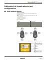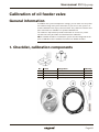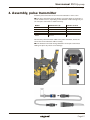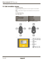
1
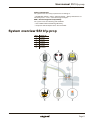
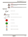
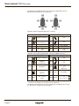
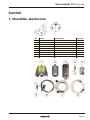
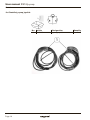
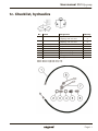
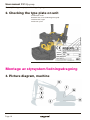
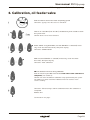
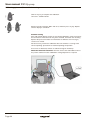
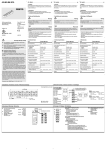
User manual SS10/μ-prop The noble art of digging Version 1.0 User manual SS10/μ-prop Table of contents Safety instructions General information.........................................................................4 System overview SS10/µ-prop....................................................5 Cautions............................................................................................6 Symbols.............................................................................................7 Control 1. Checklist, electronics..............................................................9 1b. Checklist, µ-prop joystick.................................................. 10 1c. Checklist, hydraulics........................................................... 11 2. Checking the type plate on unit......................................... 12 Montage av styrsystem(ledningsdragning) 3. Picture diagram, machine.................................................... 12 4. Line installation and mounting, stick and unit................. 13 5. Hydraulic coupling, components....................................... 14 6. Checking the hydraulic pressure....................................... 14 7. Mounting of unit module....................................................... 15 8. Line installation, machine cable.......................................... 15 9. Line installation and mounting, stick ................................ 16 10. Line installation and mounting, boom ............................. 16 11. Line installation and mounting, boom ..............................17 12. Boom root................................................................................17 13. Line installation, cab............................................................. 18 14. Connector, machine cable.................................................. 18 15. Assembly of µ-prop joystick................................................ 19 16. Protecting the line from mechanical stress..................... 19 17. Installation of cab module.................................................... 20 18. Connections, cab module................................................... 21 19. Connection of oil feeder valve............................................ 22 Calibration of thumb wheels and configuration 20. Cab module menu................................................................. 23 21. Calibration of thumb wheels and configuration.............. 24 Calibration of oil feeder valve, kontroll och montage 1. Checklist, calibration components.................................... 25 2. Checking the type plate on unit......................................... 26 3. Picture diagram, machine.................................................... 26 4. Assembly, pulse transmitter................................................ 27 5. Cab module menu................................................................. 28 6. Calibration, oil feeder valve................................................. 29 Page 3 User manual SS10/μ-prop Safety instructions Safety instructions General information This system is designed for controlling tiltrotators. System components: – Cab module (810454) – controls the system functions. – Unit module (810456) – controls the tiltrotator valves as commanded by the cab module. – Oil feeder valve (810462) – proportionally controls the hydraulic oil flow as commanded by the cab module. – µ-prop joystick (810140) for manipulating the tiltrotator functions. – Implement lock switch (810459). – Cables, hoses and other components for assembly. The system has automatic calibration functions, and the system’s functions can be customised. A μ-prop calibration kit is required in order to customise the functions (1007528). These assembly instructions provide installation instructions and information relevant to the 10/µ-prop control system. The safety information in these instructions relates directly to the 10/µ-prop and does not regard the base machine. In addition to these assembly instructions, you should carefully read the safety information regarding the base machine and any other equipment you will be using. CAUTION Do not attempt to install, use or perform maintenance on the tiltrotator/rotator and its enclosed equipment before carefully reading all the information regarding the tiltrotator/rotator, its related equipment and the base machine. Observe all safety instructions carefully. NB: There are further safety instructions in the instruction manual for the rotator. Identification and marking of the tiltrotator/rotator Check that the information in “Certification of conformity” corresponds to the information on the machine (see point 2, “Checking the type plate”), the equipment and the documentation. In the event of non-conformities, contact your supplier before first assembly. Carefully read all warning texts before assembling or using the tiltrotator/ rotator and its accompanying equipment. The warning texts explain potential risks and how to avoid them. If in any doubt, contact your employer or supplier. Remember that sound judgment and thorough knowledge of your machinery reduces many unnecessary risks. Consequently, operators should take the time to learn safe use of the tiltrotator/rotator and its related equipment before starting operation. Page 4 User manual SS10/μ-prop Safety instructions Safety requirements The system meets the safety requirements according to: – SS-EN ISO 13849-1: 2006 – Machine Safety – Safety-related Parts of Control Systems – Part 1: General Design Principles. EMC – Electromagnetic Compatibility The system meets the following CE standards: – ISO 13766:2006 Earth Moving Machinery. – European Vehicle Requirements 2004/104/EC. System overview SS10/µ-prop Pos. 1 2 3 4 5 6 Article no. 810456 810140 810454 810459 810462 Tiltrotator Page 5 User manual SS10/μ-prop Safety instructions Cautions CAUTION Faulty installation can be dangerous. If in any doubt, contact your dealer or engcon Nordic AB. CAUTION Ensure that the hydraulic system is decompressed before starting work on the system. Risk of personal injury. NB: Observe the maximum input pressure and maximum input flow. This applies to all control systems. See technical data. CAUTION Switch off the power when working with the electrical system and remove rings, watches etc. before starting work. Risk of personal injury. CAUTION Never use your hands to check for leaks in the hydraulic system. Hydraulic oil under pressure can penetrate the skin causing serious injury. CAUTION Implements connected to the tiltrotator / rotator may not be used unless correctly locked into place. ALWAYS make sure that the lock bolts protrude according to the specifications for the relevant quick hitch. CAUTION Take care if using a ladder to install parts. Risk of personal injury. CAUTION Never attempt to increase the equipment’s maximum capacity by making modifications without the supplier’s approval. CAUTION Short circuits in electrical cables can cause injury and burning. Insulate electrical conductors and parts carefully when installing electrical equipment. CAUTION Risk of burn injuries from hot hydraulic oil. CAUTION The machine must never be operated with the implement lock switch turned on, except when attaching or detaching a bucket or implement.. Page 6 User manual SS10/μ-prop Safety instructions CAUTION If in any doubt regarding the machinery or the safety features, contact an engcon dealer or engcon Nordic AB. CAUTION Risk of catching in moving parts. Risk of personal injury. Symbols Implement lock switch. Risk of damage and / or personal injury. CAUTION Read the enclosed documentation for more information. No / Wrong action. Yes / Correct action. Implement lock switch not activated. Implement lock switch activated. Page 7 User manual SS10/μ-prop Safety instructions The diagrams and tables below show the factory configurations for the buttons and thumb wheels on the joysticks. Tiltrotator without integrated grab (User 1 and 3*). Left µ-prop joystick Right µ-prop joystick JL:3 (1) Rotation clockwise JR:3 (1) Tilt JL:3 (2) Rotation anti-clockwise JR:3 (2) Tilt JL:6 – JL:7 AUX – Extra 1A+2A JR:6 AUX JR:7 – Extra 1B+2B – JR:3 – Extra 1+2 AUX JR:8 SHIFT JL:3 – Extra 1+2 AUX JL:8 SHIFT Tiltrotator with integrated grab; EC02 and EC05 (USER 2 and 4*). Left µ-prop joystick Right µ-prop joystick JL:3 (1) Rotation clockwise JR:3 (1) Tilt JL:3 (2) Rotation anti-clockwise JR:3 (2) Tilt Extra 2A** JR:6 Optional grabber close or Extra 1B JL:6 AUX Optional grabber open or JR:7 AUX Extra 1A JL:7 JL:8 SHIFT JL:3 – Extra 2 AUX JR:8 SHIFT Extra 2B** JL:3 (1) – Grab close JL:3 (2) – Grab open * User options in cab module menu ** Function not available on tiltrotators EC02 and EC05. The buttons and thumb wheels can be configured according to the customer’s preferences using the µ-Conf software. Page 8 User manual SS10/μ-prop Control Control 1. Checklist, electronics No. 1. 2. 3. 4. 5. 6 7. 8. 9. Article 810454 810456 1008739 810462 810465 810460 810457 810459 810478 Designation Cab module Unit module Safety plate, unit module Oil feeder valve Assembly kit Cable assembly X2 Machine cable Implement lock Blocking kit Quantity 1 1 1 1 1 1 1 1 1 Page 9 User manual SS10/μ-prop Control 1b. Checklist, µ-prop joystick No. Article Designation 1. 810140µ-prop joystick Page 10 Quantity 2 User manual SS10/μ-prop VARNING Risk för person- Control och/eller mate 1c. Checklist, hydraulics Läs medföljande dokumentatio info. No. Article 1. 740408 740409 2. Machine-specific 3. Machine-specific 4. 710704 5. 790114 6. 790115 7. 790118 8. 790121 Designation Quantity Hydraulic hose with couplings 3/8” free end 2 Hydraulic hose with couplings 1/2” free 2 Nejend / Felaktig åtgärd Tredo washer 4 Adapter Tredo washer 2 Hydraulic coupling 2 Hydraulic coupling 2 Dust guard 2 Ja / korrekt åtgärd2 Dust guard EC02–EC15 = Hydraulic hose 3/8” EC20–EC30 = Hydraulic hose 1/2” -4- Page 11 User manual SS10/μ-prop Control | Montage av styrsystem/ledningsdragning 2. Checking the type plate on unit A=Tiltrotator model B=Quick hitch, lower (GR=Integrated grab) C=Quick hitch, upper D=Control system Montage av styrsystem/ledningsdragning 3. Picture diagram, machine Page 12 User manual SS10/μ-prop Montage av styrsystem/ledningsdragning 4. Line installation and mounting, stick and unit 1. Cut the free end of the hydraulic hose to the correct length. Press measurements: 740408 = 20.0 mm, 740409 = 23.4 mm 2. Connect the power line to 252297. Page 13 User manual SS10/μ-prop Montage av styrsystem/ledningsdragning 5. Hydraulic coupling, components Pos. 1. 2. 3. 4. 5. Art. no. Tredo washer* Adapter* 710704 790114 790115 * Machinespecific 6. Checking the hydraulic pressure The pressure may only be adjusted by an authorised workshop according to the relevant specifications. Max. supply pressure: 22.5 MPa, 225 Bar, 3263 PSI Max. return pressure: 2.5 MPa, 25 Bar, 363 PSI Page 14 User manual SS10/μ-prop Montage av styrsystem/ledningsdragning 7. Mounting of unit module Pos. 1. 2. 3. Art. no. Machine stick 1008739 810456 8. Line installation, machine cable NB: The connector piece reinforced with shrink sleeving should be mounted on the unit module. Page 15 User manual SS10/μ-prop Montage av styrsystem/ledningsdragning 9. Line installation and mounting, stick 10. Line installation and mounting, boom Page 16 User manual SS10/μ-prop Montage av styrsystem/ledningsdragning 11. Line installation and mounting, boom 12. Boom root Page 17 User manual SS10/μ-prop Montage av styrsystem/ledningsdragning 13. Line installation, cab NB: The implement lock should be positioned so that it cannot be activated unintentionally. 14 . Connector, machine cable Detach the connector from the machine cable if necessary. Reassemble the cabling as shown in the picture. NB: The picture shows the back of the connector. Page 18 User manual SS10/μ-prop Montage av styrsystem/ledningsdragning 15. Assembly of µ-prop joystick The two joysticks are identical. It makes no difference which joystick is installed to the right and to the left. 1. Adjust the distance (A) by carefully bending the joysticks as shown (1) so that they fit the machine’s control levers. 2. Mount the joysticks on the machine’s levers. Position the fork of the joystick underneath the machine’s control lever. Screw into place with the four screws. 16. Protecting the line from mechanical stress 3. Position the lines so that they are not in the way of the machine operator. Make sure the lines are free of stress when the levers are pushed to their end positions. Page 19 User manual SS10/μ-prop Montage av styrsystem/ledningsdragning 17. Installation of cab module NB: The cab module display must be visible when the system is later configured and calibrated. Free space, cab module. Page 20 User manual SS10/μ-prop Montage av styrsystem/ledningsdragning 18. Connections, cab module Pos. 1. 2. 3. 4. 5. Art. no. 810456 A: 810462 B: Power supply, ignition on. 810459 810140, left 810140, right NB: Check that the left and right µ-prop joysticks are connected to the correct connection points in the cab module. NB: Securely screw the connector for the µ-prop joystick and the implement lock into the connection points on the cab module. Page 21 User manual SS10/μ-prop Montage av styrsystem/ledningsdragning 19. Connection of oil feeder valve RED = P (pressure) BLUE = T (tank) YELLOW = A/B (servo) Also see the documentation/hydraulic diagram for the machine. Install underneath the cab floor next to the pedal. Page 22 User manual SS10/μ-prop Calibration of thumb wheels and configuration Calibration of thumb wheels and configuration 20. Cab module menu General information The left and right µ-prop joysticks are used to navigate in the cab module menu. NB: It is not possible to navigate in the cab module menu with µ-Conf connected. JL = Left µ-prop joystick JR = Right µ-prop joystick CM = Cab module Button JL:7+ JR:6 5 seconds JL:6+ JR:7 5 seconds JR:3 JL:3 JL:6, JL:7, JL:8, JR:6, JR:7, JR:8 Function CM Activate menu Activate menu Up/down in the menu SELECT or EXIT Confirm selection/continue Page 23 User manual SS10/μ-prop Calibration of thumb wheels and configuration 21. Calibration of thumb wheels and configuration Power the system by switching it on. CM shows “µ-PROP”, then “JOYSTICK CALIBRATION”. Release JL:3 and JR:3, then press any key. CM shows zeroed/calibrated values for the thumb wheels. Push JL:3 and JR:3 to their end positions to the right and left. CM shows zeroed/calibrated values for JL:3 and JR:3 and “Press any key to exit”. Press any key to continue. CM shows list of available tiltrotator models. Choose the relevant tiltrotator with JR:3. Make sure that “SELECT” is selected (if necessary, use JL:3 to move the cursor), then press any key. CM shows “µ-PROP” for a few seconds, then “SAVED SETTINGS”. Problem solving If no text appears when the cab module display is switched on, check the fuses and power supply connections to the cab module. If the cab module display signals an error during calibration, check and correct the connections where the error may have occurred. For information on different error messages, see the user manual. If no errors are detected, contact an authorised engcon workshop. Now continue with “Calibration of oil feeder valve”. Page 24 User manual SS10/μ-prop Calibration of oil feeder valve Calibration of oil feeder valve General information To calibrate the system and adjust the settings, you can either use the µ-Conf PC software along with a pulse transmitter, or you can use the system’s automatic calibration with only a pulse transmitter. The µ-Conf PC software and pulse transmitter are available in a separate calibration kit. The software’s help function provides information on now to use µ-Conf. This document only describes the automatic basic calibration. NB: If a double oil feeder is installed, the system must be configured for this prior to calibration. See installation instructions for double oil feeder. 1. Checklist, calibration components No. 1. 2. 3. 4. Article 810467 810464 810461 810466 Designation USB cable Cable, pulse transmitter Pulse transmitter with lock nuts USB with µ-Conf software Quantity 1 1 1 1 Page 25 User manual SS10/μ-prop Kalibrering pytsarventil, kontroll och montage 2. Checking the type plate on unit A=Tiltrotator model B=Quick hitch, lower (GR=Integrated grab) C=Quick hitch, upper D=Control system 3. Picture diagram, machine Page 26 User manual SS10/μ-prop Kalibrering pytsarventil, kontroll och montage 4. Assembly, pulse transmitter Install the pulse transmitter on the end of the tiltrotator’s worm screw. NB: The pulse transmitter must be fitted at a specific depth or screwed in a certain number of turns, depending on the tiltrotator model. Damage may occur if the pulse transmitter is fitted incorrectly. Model EC05 EC05B EC10/20 EC15 EC30 Dimensions (A) 16 mm 18,5 mm 15,5 mm 17,5 mm 21 mm Number of turns 16 18,5 15,5 17,5 21 Connect the pulse transmitter cable to the pulse transmitter, and to the connection for the tiltrotator cable assembly. NB: The tiltrotator will rotate during calibration. Fix the pulse transmitter cabling into place to protect it from damage. Page 27 User manual SS10/μ-prop Kalibrering pytsarventil, kontroll och montage 5. Cab module menu General information The left and right µ-prop joysticks are used to navigate in the cab module menu. NB: It is not possible to navigate in the cab module menu with µ-Conf connected. JL = Left µ-prop joystick JR = Right µ-prop joystick CM = Cab module Page 28 Button JL:7+ JR:6 5 sekunder JL:6+ JR:7 5 seconds JR:3 JL:3 JL:6, JL:7, JL:8, JR:6, JR:7, JR:8 Function CM Activate menu Activate menu Up/down in menu SELECT or EXIT Confirm selection/ continue User manual SS10/μ-prop Kalibrering pytsarventil, kontroll och montage 6. Calibration, oil feeder valve Start the machine and run the motor at operating speed. CM shows “µ-prop”, then the screen is turned off. Click on JL:7 and JR:6 (or JL:6+ JR:7) simultaneously for 5 seconds to show the system menu. CM will show a list of menu functions. Select “AUTO” using JR:3. Make sure that ”SELECT” is selected (if necessary, use JL:3 to move the cursor), then press any key. CM shows “START AUTO”. Make sure that “SELECT” is selected (if necessary, use JL:3 to move the cursor), then press any key. CM shows “Auto calibration”. NB: The tiltrotator will move during calibration. Push JL:3 as far as possible to the left and hold it there until calibration is completed, (see section 7). CM will now show the different calibration steps performed by the system. The LED on the pulse transmitter indicates when the rotator’s worm screw is rotating. CM shows “Saved settings” and the calibrated values after calibration is completed. Release JL:3. Continued on next page. Page 29 User manual SS10/μ-prop Kalibrering pytsarventil, kontroll och montage Click on any key to complete the calibration. CM shows “START AUTO”. Exit the menu by selecting “EXIT” with JL:3, and then press any key. Repeat until the display is turned off. Problem solving If the cab module display signals an error during calibration, check and correct the connections where the error may have occurred, and check the mounting depth of the pulse transmitter. For information on different error messages, see the user manual. For best results, perform the calibration when the machine is running at the correct operating speed and has reached operating temperature. If no errors are detected, contact an authorised engcon workshop. Check the tiltrotator functions: Connect a PC to the cab module and use the µ-Conf software if further calibration/ setting adjustment is required. Page 30 Production: Syre | Print: Berndtssons Tryckeri, 2009 engcon Nordic engcon UK engcon Germany engcon Finland engcon Denmark engcon Poland engcon Sweden/Nordic/Holding, PO Box 111, SE-833 22 Strömsund, Sweden Phone: +46 670 178 00 • Fax: +46 670 178 28 [email protected] • www.engcon.com