1
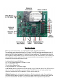
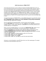
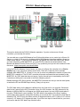
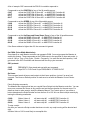
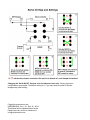
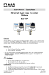
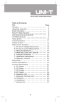
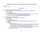
RC-WIFI CONTROLLER
USER MANUAL
In the rapidly growing Internet of Things (IoT), applications from personal electronics to industrial
machines and sensors are getting wirelessly connected to the Internet. Controlling motors and
hobby devices have been neglected in this advancement. Now that almost everyone owns some
form of portable communication device, it is only logical do to away with the bulky RC transmitter
that uses Joysticks and switches. The touch screen on modern devices can replace almost any
mechanical control input device.
At the heart of our RC-WIFI controller is a B/G/N wireless router. We use it in WIFI Access Point
mode. The WIFI to Serial converter receives and transmits data from any source that can send and
receive data on a UDP port. We use OSC (open sound control protocol) messages. This data can
address and control 8 standard RC Servos and other logic ports (216 more Servos with the Maestro
Expansion). The WIFI Transmitter has an output power of -20 dbm and comes with a 3 db antenna
with 10cm of cable and connector.
This device can replace any Rc Wireless system like the Futaba transmitter and receiver. You can
use a PC, iPad or Android device to control a large number of Rc Servos. You use visual controls
on the touch screen instead of a joystick to control Rc Servos and Relays. This system uses the
popular OSC Protocol. There are many Apps that adhere to this protocol. You do not have to write
any software. Simply attach commands to a control. To gain a more in-depth understanding of this
popular protocol go to this website. http://opensoundcontrol.org/introduction-osc
We suggest TB MIDI STUFF for iOS, which is by far the best and most flexible app. It lets you
design Sliders, Buttons, XY Pads, Indicator Lights and assign data right on the iPad without the
need for a computer. We are not connected to this developer and there are many other apps you
can use on an IOS or ANDROID device.
Features
Control 8 Rc Servo Motors from any Tablet, Phone or PC
Control up to 216 Rc Servos by adding POLOLU Maestro controllers
• The power-up default position for each Rc Servo is programmable by the user.
• The Rc Pulse is settable to a 1 ms (1 to 2ms) range or 2 ms (0.5 to 2.5ms) range.
• There are 2 digital outputs that let you control relays or LED’s.
• Data path is two-way and can send data from the RC-WIFI Controller back to the iDevice.
• One digital input lets you monitor a high or low condition on your Phone or Tablet.
• One analog input can read the voltage of the system battery for monitoring.
• Multiple data sources like an iPad, Android Device or PC can send data simultaneously.
• An Optional RS232 in/out port can be used as a wireless serial bridge. (Optional )
• The controller converts the OSC data to the POLOLU protocol.
• The Maestro Controller can also control the speed and velocity of any Rc Servo independently.
The Hardware
Before you connect any wires, you must be aware of the electrical specifications.
The controllers main power should be 6 or 7.2 volts. The WIFI Controller can withstand up to 15
volts, however, the main power source is dependent on the specs of your RC Servos. The power
input to the PCB is then regulated to 5 Volts and 3 Volts respectively. The power to the servos is
NOT regulated. Always make sure you connect POSITIVE to the correct terminal. The current you
require depends on how many Rc Servos you connect and their current specs. Here is a list of
accepted and recommended power sources.
6 volt Lead Acid or Lead Gel Battery.
4 X 1.5 volt Alkaline Batteries for a total of 6 volts
5 X 1.3 volt Lithium cells
7.2 volt Lithium Battery Pack.
Or any regulated 6 to 7 volt Power Supply.
All RC Servos will be powered from this main power source. Read the specs of the Rc Servos you
want to use before you decide on a power source. The RC Pulse is 4 to 5 volts and the 3 pin
connector complies with the RC standard, Positive on the center pin.
2 Digital Outputs are 5 volt logic level and have a 470 ohm resistor in series. You can drive an
LED direct without adding a resistor. Connecting a small mechanical or solid state relay here lets
you drive 110 volt loads. The later is only recommended for the experienced experimenter.
Digital Input: One digital input that lets you monitor an ON/OFF condition. This should be
connected to a mechanical Normally Open or Closed contact. You can NOT however connect this
input to a more than 5 volt logic signal. The input has a 470 ohm resistor for current protection.
Analog Input : The analog converter resolution is 8 bits and transmits a value from 0 to 255. The
Input has a 4:1 voltage divider and can measure voltages up to18 volts which results in a value of
255. This results in 0.07 volts per count. We recommend connecting this input to the battery plus of
your system for remote monitoring.
RC-WIFI Controller Apps
You should now be familiar with the hardware. Instructions on how to control the servos over WIFI
differ, depending on your device. Any software that is capable of sending UDP data packets on port
8899 will do.
iPad, iPhone or Android Device
Download an app that is able to transmit OSC data, like TB MIDI STUFF for IOS. There are free
OSC apps but this one is by far the best and well worth $4.90 at the APP Store. If you have an
Android device, TouchOSC is your best choice. How to setup TB MIDI STUFF is covered in a later
section. Complete test pages for TB MIDI STUFF will be e-mailed with your purchase receipt.
PC, Windows, Linux
You can use a PC to control the Rc Servos, most console softwares will let you compose and send
OSC data packets. If you are a software writer, you need to attach a UDP socket. Select port 8899
for send and receive.
RC-WIFI Data Structure
Many apps are available for the iPad and Android device which are intended for the music
enthusiast. Most of them also support the very popular OSC transmission protocol. For those who
want to get a more comprehensive insight, go to this site for a detailed description.
http://opensoundcontrol.org/introduction-osc
The OSC communication is via a UDP port. There are a number of data types in the OSC protocol.
Our controller will work with the following 2 data types.
Int16
Float32
16 bit big-endian two's complement integer
IEEE 754 Floating point number
If your APP lets you choose the data type, we recommend using the integer type. Floating point
type data is detected and gets converted to a 2 byte Integer value by the RC-WIFI Controller before
it is sent.
A detailed analysis of the data stream for those who want to write their own transmission software is
presented here. An OSC data packet, in our case, will always contain 16 bytes. Eight bytes for the
OSC Address. This is our Device Address and Command ID. The other eight bytes contain the
Servo Position or ON/OFF data in integer format. Every 16 byte OSC packet starts with a /
character.
A typical OSC data packet sending a 2 byte integer value looks like this:
ASCII = /001T- - - ,i- - - - XX
DEC = 47 48 48 49 84 0 0 0 44 105 0 0 0 0 X X
HEX = 0x2F 0x30 0x30 0x31 0x54 0x00 0x00 0x00 0x2C 0x69 0x00 0x00 0x00 0x00 0xXX 0xXX
An IEE Floating point data stream.
ASCII = /001T- - - ,f- - XXXX
DEC = 47 48 48 49 84 0 0 0 44 102 0 0 X X X X
HEX = 0x2F 0x30 0x30 0x31 0x54 0x00 0x00 0x00 0x2C 0x66 0x00 0x00 0xXX 0xXX 0xXX 0xXX
The Command Structure
/001T The first 5 bytes are used to identify the controller address, the servo or port, and the
command function. They are ASCII characters you type into an input box. The other 3 bytes remain
true zero. The /0 Is the device or controller address, and in this case, the data is intended for our
WiFi-Controller. A /1 is intended for the POLOLU Maestro Controller # 1.
The next 2 characters identify the Rc Servo Number or other control output. /001T to /007T will
address Servo 0 to 7 on the WiFi-Controller. The T is the function ID for theTarget Position of a
servo. .XX contains an integer value from 0 to 65535. This data is generated by the control object
like a slider or other control on your tablet or phone. Below is a list of the commands the RC- WIFI
controller responds to. (For the POLOLU Maestro expansion read that chapter)
/000T to
/007T
This will position 8 different RC Servos to a position the OSC control generates (0-255)
/000T
/001T
/004T
/007T
sets the POSITION of Servo #0
sets the POSITION of Servo #1
sets the POSITION of Servo #4
sets the POSITION of Servo #7
connected to the RC-WIFI controller.
connected to the RC-WIFI controller.
connected to the RC-WIFI controller.
connected to the RC-WIFI controller.
/001D and /002D
These two commands can set 2 Digital output ports on the RC-WIFI controller to HIGH or LOW.
There is a 470 Ohm resistor in line on each output and is able to drive an LED without the current
limiting resistor. Connecting a solid state relay here, lets you drive 110 volt loads. The OSC control
generates (0) for OFF and (1) for ON
Setup Commands:
These commands are used to set flags in the controller. These settings are stored in internal
nonvolatile memory that are used when the unit powers up. All Setup commands have an X in the
5th byte. One such command is to set the RC Pulse to either 1ms or 2ms. If you are not sure, leave
it set to 1ms. Another command sets one servo of your choice to that default position on power-up.
/F00X
set the controller to produce a 1ms RC Pulse
/F01X
set the controller to produce a 2ms RC Pulse
Most servos rotate 90 degrees if a 1ms pulse window is used. Some servos can rotate 180 degrees
when controlled with a 2ms pulse. OSC control Data is ignored
/D00X
set the present position of Servo 0 to be the default position.
/D01X
set the present position of Servo 1 to be the default position.
/D07X
set the present position of Servo 7 to be the default position.
On Power-up, all Servos will go to the default position that were set with this command.
At any time during operation you can force all servos to their default position.
/S00X
set all 8 servos to their default position.
The RC-WIFI controller can also send data out to the iPad, Android device or a PC. Whenever the
RC-WIFI controller sends data out and that same command was attached to a control like a Slider,
that slider will move to that position. All controls in TB MIDI can send and receive data. A Master
Enable flag must be set first for this feature to be enabled
This feature is disabled on power-up and must be re-enabled every time you start the RC-WIFI
controller. This was done to deal with a bug in TBMIDI. If data is received by TBMIDI before it is
properly initialized it will crash. You must send the command /F71X to the RC WIFI controller
before it sends out any data. You can design a button and attach an OSC AFTERTOUCH
Message.
/F71X to turn on data from RC-WIFI controller.
/F70X to turn off data from RC-WIFI controller.
A Heartbeat signal is sent every 0.5 seconds from the RC WIFI controller to indicate you have a life
WIFI connection. You can design an LED or other indicator on your pad and add an OSC Message.
The LED will flash on and off when the RC-WIFI controller is not busy doing other work.
/009P
There are several indicator OSC messages that are sent out by the controller. Two inputs on the
RC-WIFI controller can be monitored remotely. To make a connection to these 2 inputs, please
read the section on Hardware.
One digital input lets you attach a switch.
/001P
This data is sent from the controller and can be attached to an indicator control on the iPad to
monitor an ON or OFF condition. The OSC control receives a 0 value to indicate OFF and any
larger value than 0 indicates ON.
One analog input.
/001A
This is the ID for the analog converter data and contains a value from 0 to 255. A vertical slider can
be used to monitor the battery voltage sent from the RC WIFI controller. This data gets sent out
when the AD value changes
If Data Out from WIFI Controller was previously enabled with the command /F71X .
When you now issue the command /S00X to set all 8 servos to their default position, it will move all
sliders, or other controls, on your iPad. We use this feature to synchronize all control objects to that
Servo position.
NOTE: Some OSC Apps assume the / character that identifies the data as an OSC packet. You
may have to omit this first character in some apps since it is added automatically. You may end up
sending // and corrupt the data.
QUICK Start Guide for TBMIDI STUFF
These instructions assume you have an iPhone or iPad and installed TB Midi Stuff. By now you
have connected the power source and at least one RC Servo to the RC-WIFI controller. In order to
move a servo and make it work, you need some way of sending data to the RC WIFI Controller.
You will need to purchase and download any APP that lets you send OSC data. There are several
free apps, but the TB MIDI STUFF for IOS app is the one we suggest. To save you time, we have
made up several template pages for the TB MIDI STUFF app. These pre-made pages contain
control samples to turn your iDevice into a powerful control center. You can use these pages as a
learning center for TB MIDI STUFF and get the basics on how to setup the controls and attach data
to them.
To import these pages into TB MIDI STUFF, you must E-Mail these pages to yourself. After opening
this E-Mail, press and hold your finger on one of the E-Mail attachments, a window will pop up and
ask you Open With ? Select TB MIDI STUFF as your destination. This app will open automatically
and import the page. Repeat this for all pages.
Once you have done this and applied power, you have to login to the WIFI module.
Go to the SETTINGS page on your iPad. Then click on WI-FI and select RC-254 from the list of
available networks. To login, type the password, rcservo254 This is the default password for the
controller which you can change later.
When you have successfully logged on, you can open the TB MIDI STUFF App. Before you can
communicate with the RC-WIFI module, you have to make settings in TB MIDI STUFF.
Click on the Tool Wrench on the top right. A menu will pop up that you can scroll up or down.
In subgroup MidiSettings select WiFi Network: Session1 for both Midi IN and Midi Out.
In subgroup Persistence slide the knob next to “Restore last pages canvas at launch” to the right
so the color changes to green.
In subgroup OSC , Enable field, slide the knob to the right so it will turn green.
In subgroup OSC , Host field ,type 10.10.100.254
In subgroup OSC , Outport field, type 8899
In subgroup OSC , Inport field, type 8899 if you want two way communication.
At his point you should be able to control RC Servos from one of the sample pages. The sample
controls are for servos attached to port 6 and 7.
TBMIDI Instructions for control object settings.
These instructions only apply to TBMIDI Stuff App. Every control object, a slider, button or knob,
has two main values you have to set. One is the OSC data which is the servo position, the other is
the objects step resolution of the servo. You should ignore any reference to MIDI data. These
instructions assume you have loaded one of the sample control pages we supplied.
On the very top in any TBMIDI page, tab on EDIT > Enter Page Editor. Now double tab on a slider.
The Control Settings page will pop up. Ignore any settings not mentioned here. First scroll down to
OSC Messages and tab on it. Another window will pop up and display /007T or similar. Tab on the
line to view detailed data. This is the OSC data assigned to a slider that will position a servo. The
min value 0 and max value 255 represent the position range. 0 is the most right and 255 the most
left turn position of your servo. You can change these values to suit your needs. You can also make
a Servo run in the opposite direction by setting the High value to zero and the Low value to 255.
Your servo will turn about 90 degrees with these settings.
Now tab Done > Control Settings. Scroll up to Steps Count.
This value represents how many steps the slider will resolve when you move it from one extreme
end to the other. This is NOT the servo position. Each OSC servo data on a slider can send 255
positions for a 90 degree servo turn. That is 0.035 degrees per step. Most RC servos can not
resolve such a small angle. So why send data more often than necessary. A Steps Count value of
127 will turn a servo by 127 steps or 0.07 degrees per step. This means the number of RC Servo
positions will be divided by the control resolution value. If for example, your OSC data is 0 and 255
and you set the control resolution value to 4, then your servo will jump from position 0 to 85 to 170
to 255. If you like to set stops or travel limits for your servo, you have to alter the OSC data's top or
bottom value.
POLOLU Maestro Expansion
This section deals with the POLOLU Maestro expansion. If you do not have one of these
controllers, you can skip this section.
You can add one or more MINI Maestros from Pololu which allows you to control up to 9 times 24
Servos, or a total of 216 servos by chaining multiple MINI Maestro controllers together. Above is a
simple wiring sample. To connect more Maestros, just parallel the Power and Serial Lines. Before
you start connecting a MINI MAESTRO, go to the POLOLU website and download their User
Manual and Maestro Control Center on to a PC. Any questions you may have are answered in that
document. https://www.pololu.com/docs/0J40/all
Using the POLOLU Maestro Control Center, you have to configure the controller to be a Device
Number from 1 to 9. Any other number will not work. There are 3 versions of this controller
available. MINI MAESTRO 12, 18 and 24. You can of course only address the number of servos the
MAESTRO is capable of. The RC-WIFI controller will accept commands that are intended for the
MAESTRO. Any OSC data that does not have a 0 as the second byte is translated by the Rc-WIFI
Controller on the fly and is converted to the Pololu Maestro protocol.
Besides setting the RC Servo position, the MAESTRO Controller also lets you set the travel speed,
as well as the UP and DOWN Slope Velocity (Ramp) of any servo.
The OSC data setting for the Maestro is different from the 8 servos for our controller. Each servo
data for the 8 servos on the WIFI Controller is from 0 to 255. However, the OSC data sent to the
Maestro is 8000 to16000 for a 90 degree turn. 8000 equals about 1ms and 16000 equals about 2
ms pulse. TB Midi has 2 control settings. The OSC data for the position of the Servo, and the
control object step resolution setting that should be no more than 255. This means the OSC Data is
divided by 255. An RC Servo can barely resolve 90 degrees divided by 255. A value of 127 will turn
a servo by 127 steps or 0.07 degrees per step. If you like to set stops or travel limits for your servo,
you have to alter the OSC data's top or bottom value.
A list of example OSC commands the POLOLU controller responds to:
Commands to set the POSITION of any of the 24 possible servos.
/100T
will set the POSITION of Servo #0 on MAESTRO Controller #1
/101T
will set the POSITION of Servo #1 on MAESTRO Controller #1
/211T
will set the POSITION of Servo #11 on MAESTRO Controller #2
/921T
will set the POSITION of Servo #21 on MAESTRO Controller #9
Commands to set the SPEED of any of the 24 possible servos:
/100S
will set the SPEED of Servo #0 on MAESTRO Controller #1
/101S
will set the SPEED of Servo #1 on MAESTRO Controller #1
/211S
will set the SPEED of Servo #11 on MAESTRO Controller #2
/921S
will set the SPEED of Servo #21 on MAESTRO Controller #9
Commands to set the Up Slope and Down Slope (Ramp) of any of the 24 possible servos:
/100R
will set the RAMP of Servo #0 on MAESTRO Controller #1
/101R
will set the RAMP of Servo #1 on MAESTRO Controller #1
/211R
will set the RAMP of Servo #11 on MAESTRO Controller #2
/921R
will set the RAMP of Servo #21 on MAESTRO Controller #9
If the Servo address is higher than 23, the command is ignored.
Set PWM (Pulse Width Modulation)
One channel on each Maestro controller can generate PWM. You must program the Maestro to
enable this feature. These commands set the PWM output to the specified on time and period, in
units of 1/48 µs. Time = Duty Cycle, Period = Frequency. You must first set the frequency. It will
get stored in the WIFI-Controller and then sent with the duty cycle command.
.
OSC protocol:
/100F
/100D
FREQUENCY Gets stored and sent with next command
2 byte DUTY CYCLE and 2 byte FREQUENCY STORED IN PIC
Go Home:
This command sends all servos and outputs to their home positions, just as if an error had
occurred. The Home or Default position of each servo is set with the Maestro Control Center.
/100H
Pololu Scripting commands:
The Maestro has a feature that lets you compile Servo Scripts into the Maestro controller. You can
move one or several Rc Servos to any position and set the time duration for the next move. For
details on how to make a script, study the Maestro Manual. The Control value of your slider or
button determines the Script Number and can be from 0 to 125. We can Start a script remotely by
issuing the following commands.
/100Q
/101Q
/203Q
Button Value= 0
Button Value= 1
Button Value= 3
will start script #0
will start script #1
will start script #3
on MAESTRO Controller #1
on MAESTRO Controller #1
on MAESTRO Controller #2
To stop a script:
Any time you execute a Script number that does not exist, any script running will be aborted and
stop.
A Button Value of 126 is most likely to accomplish this.
USR-WIFI Module Setup
This section is for the advanced user that is familiar with WIFI networking. You can change the
network setup, or just the Name and Password.
Once you have powered up the controller, a green light will go on and blink on the WIFI module.
Now you have to log on to the WIFI module like any other network. It functions as an access point
like the WIFI Router at your home.
To change any settings in the WIFI Module, your Computer or Tablet must be connected to network
name ” RC-254 “ This is the default name you can change later.
When your device tells you that you have connected successfully, you are ready to go.
You will now have to Open a Web-browser on your Tablet or PC and type:
HTTP:// 10.10.100.254
User Name: admin
Password:
admin
When prompted...
If your log-on is successful, you should see the window below.
You can change the default settings in the WIFI Module, like the Name, Password, IP Address,
UDP port # etc. Make a written note of all changes you make. Most settings are self-explanatory. If
you don’t understand what they are for, Do Not change them. Do not change to STA Mode.
Anytime you have changed a setting, click APPLY before making more changes. After you are
done making all the changes, go to Device Management and click on Restart.
WIFI Module default settings are:
IP:
10.10.100.254
Port:
8899
Protocol:
UDP
Serial baud rate:
57.6KB
Password:
rcservo254
Can be changed but not advisable.
Can be changed
Must stay at UDP, all OSC apps use UDP, not TCP/IP
Must stay at 57.6KB
Can be changed
Changing the Serial IN/OUT Jumpers is for the advanced user only. Various serial port
configurations are possible. The default setting is A. If you only need to control Rc Servos,
disregard any other setting.
Copyright rcpowerservo.com
USER MANUAL Ver. 1.20 Nov. 25 - 2015
This Manual will be updated without notice.
Please report any errors or omissions to
[email protected]