1
Thank You for purchasing this
Factory Service Manual on EBAY
from PCTECHINFO!
Click Here for more Factory Service
Manuals for other Computer and
Printer / Copier Manufacturers
from PCTECHINFO!
OKIPAGE20 / OKIPAGE20n
LED Page Printer
Maintenance Manual
ODA/ OEL/ INT
All specifications are subject to change without notice.
PostScript, Adobe and the PostScript logo are trademarks of Adobe Systems Incorporated, registered
in the U.S.A.
*Times, Helvetica and Palatino are trademarks of Linotype AG and/or its subsidiaries.
ITC Avant Garde Gothic, ITC Zapf Chancery, ITC Zapf Dingbats and ITC Bookman are registered
trademarks of International Typeface Corporation.
HP and LaserJet are registered trademarks of Hewlett-Packard Company.
Diablo 630 is a registered trademark of Xerox corporation.
AppleTalk is a registered trademark of Apple Computer, Inc.
LocalTalk is a trademark of Apple Computer, Inc.
PREFACE
This maintenance manual describes the field maintenance methods for OKIPAGE20 / OKIPAGE20n.
This manual is written for use by maintenance personnel. Note, however, that the user should refer to
the USER’S MANUAL for methods of handling and operating the equipment.
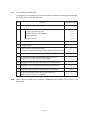
CONTENTS
1. CONFIGURATION ....................................................................................... 1 - 1
1.1
1.2
1.3
1.4
1.5
System Configuration ................................................................................................. 1 - 1
Printer Configuration .................................................................................................. 1 - 2
Optional Configuration ............................................................................................... 1 - 3
Specification ............................................................................................................... 1 - 5
Safety Standards ....................................................................................................... 1 - 7
1.5.1 Certification label .......................................................................................... 1 - 7
1.5.2 Warning label ................................................................................................ 1 - 7
2. OPERATION DESCRIPTION ...................................................................... 2 - 1
2.1
2.2
2.3
2.4
2.5
2.6
2.7
2.8
2.9
Main Control Board (BOARD-AAA) ........................................................................... 2 - 3
Power Supply Unit ..................................................................................................... 2 - 7
Electro-photographic Process .................................................................................... 2 - 9
2.3.1 Electro-photographic process mechanism ................................................... 2 - 9
2.3.2 Electro-photographic process ....................................................................... 2 - 11
2.3.3 Process operation descriptions .................................................................... 2 - 15
2.3.4 Revision of LED Head Illumination ............................................................... 2 - 25
Paper Jam Detection ................................................................................................. 2 - 30
Cover Open ................................................................................................................ 2 - 31
Toner Low Detection .................................................................................................. 2 - 32
Stacker-full Detection ................................................................................................. 2 - 34
Page Size Detection .................................................................................................. 2 - 34
PostScript ROM module (BOARD-MSM or BOARD-FSL) ......................................... 2 - 34
3. PARTS REPLACEMENT ............................................................................. 3 - 1
3.1
3.2
3.3
Precautions for Parts Replacement ........................................................................... 3 - 1
Parts Layout ............................................................................................................... 3 - 3
How to Change Parts ................................................................................................. 3 - 6
3.3.1 Face -up Stacker Assy ................................................................................. 3 - 7
3.3.2 Contact Assy ................................................................................................ 3 - 8
3.3.3 DC Fan Motor ............................................................................................... 3 - 9
3.3.4 OP Panel Assy ............................................................................................. 3 - 10
3.3.5 Board-AAA .................................................................................................... 3 - 11
3.3.6 Stacker Assy, Damper Arm, Cover Rear ..................................................... 3 - 12
3.3.7 Sensor Stacker Full ...................................................................................... 3 - 13
3.3.8 Cable cover (guide film) ................................................................................ 3 - 14
3.3.9 Damper ......................................................................................................... 3 - 15
3.3.10 Feeder Unit-Front ......................................................................................... 3 - 16
3.3.11 Roller Assy-Regist ........................................................................................ 3 - 17
3.3.12 Motor -Main .................................................................................................. 3 - 18
3.3.13 Guide Assy-Eject .......................................................................................... 3 - 20
3.3.14 Heat Assy ..................................................................................................... 3 - 21
3.3.15 Roller feed (C) .............................................................................................. 3 - 22
3.3.16 Roller Assy-BK ............................................................................................. 3 - 23
3.3.17 Roller Assy-Feed .......................................................................................... 3 - 24
3.3.18 LED Head ..................................................................................................... 3 - 25
3.3.19 Paper cassette, ROLLER Ass-Feed, ROLLER-Assy-Hoppibg ..................... 3 - 26
3.3.20 Frame Assy-Separation ................................................................................ 3 - 27
3.3.21 Transfer Roller/TR Gear/TR Bearing ............................................................ 3 - 28
3.3.22 EP lock shaft ................................................................................................. 3 - 29
3.3.23
3.3.24
3.3.25
3.3.26
3.3.27
3.3.28
3.3.29
3.3.30
LEVER Assy- Out Sensor ............................................................................. 3 - 30
Toner sensor lever........................................................................................ 3 - 31
Paper sensor lever ....................................................................................... 3 - 32
Inlet sensor lever .......................................................................................... 3 - 33
Power supply unit ......................................................................................... 3 - 34
Lever-Paper end & Lever-Paper near end ................................................... 3 - 35
Guide Assy-Cassette (L) .............................................................................. 3 - 37
Guide Assy-Cassette (R) .............................................................................. 3 - 38
4. ADJUSTMENT ............................................................................................. 4 - 1
4.1
4.2
Maintenance Modes And Functions ........................................................................... 4 - 1
4.1.1 User maintenance mode .............................................................................. 4 - 3
4.1.2 System maintenance mode .......................................................................... 4 - 7
4.1.3 Engine maintenance mode ........................................................................... 4 - 10
4.1.4 EEPROM initialization .................................................................................. 4 - 14
Adjustment When Replacing A Part ........................................................................... 4 - 15
4.2.1 Resetting the fuser counter .......................................................................... 4 - 16
4.2.2 Destination setting ........................................................................................ 4 - 17
5. PERIODIC MAINTENANCE ........................................................................ 5 - 1
5.1
5.2
Periodic Replacing Part ............................................................................................. 5 - 1
Cleaning ..................................................................................................................... 5 - 1
5.2.1 Cleaning of LED lens array........................................................................... 5 - 1
5.2.2 Cleaning the Plastic Film .............................................................................. 5 - 2
6. TROUBLESHOOTING PROCEDURES ...................................................... 6 - 1
6.1
6.2
6.3
6.4
6.5
Troubleshooting Tips ................................................................................................. 6 - 1
Points to Check before Correcting Image Problems .................................................. 6 - 1
Tips for Correcting Image Problems .......................................................................... 6 1
Preparation for Troubleshooting ................................................................................ 6 - 2
Troubleshooting Flow ................................................................................................. 6 - 2
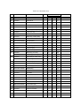
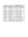
6.5.1 LCD status message/trouble list ................................................................... 6 - 2
6.5.2 LCD message troubleshooting ..................................................................... 6 - 14
6.5.3 Image troubleshooting .................................................................................. 6 - 34
7. WIRING DIAGRAM ...................................................................................... 7 - 1
7.1
7.2
7.3
7.4
Interconnect Signal Diagram ...................................................................................... 7 - 1
PCB Layout ................................................................................................................ 7 - 2
Resistance Check ...................................................................................................... 7 - 5
Program/Font ROM Location ..................................................................................... 7 - 7
8. PARTS LIST ................................................................................................ 8 - 1
APPENDIX
APPENDIX
APPENDIX
APPENDIX
APPENDIX
A
B
C
D
E
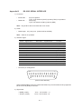
CENTRONICS PARALLEL INTERFACE ................................ A - 1
RS-232C SERIAL INTERFACE ............................................... B - 1
DUPLEX UNIT .......................................................................... C - 1
Second/ Third Paper Feeder .................................................. D - 1
Multi Feeder ............................................................................ E - 1
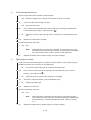
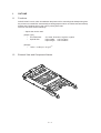
1. CONFIGURATION
1.
CONFIGURATION
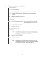
1.1
System Configuration
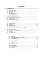
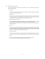
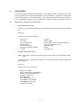
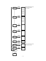
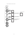
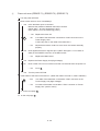
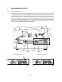
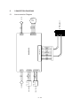
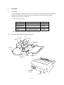
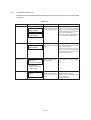
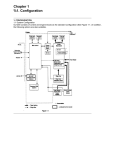
OKIPAGE20 / OKIPAGE20n consists of control and engine blocks as the standard configuration (See Figure 1-1.)
In addition, the following options are also available.
AC IN
120V
230V
Printer
Operator
panel
PC etc.
Face up
stacker
Face down
stacker
Power/
Sensor
Board
Main control
Printer
Mechanism
*
I/D unit
Centronics
Parallel interface
(Bidirection)
*
DC Fan
Toner Cartridge
Front Feeder
LED head
Motor-Main
Hopping motor
RS-232C
Serial I/F
LAN etc.
OKI HSP
interface board
(Option)
Paper tray
Paper size
detection switch
Extension D-RAM
SIMM
(Option)
or
4MB/ 8MB
Flash ROM SIMM
(Option)
PostScript
SIMM
(Option)
High Capacity
Second Paper
Feeder
(Option)
Multi Feeder
(Option)
High Capacity
Third Paper
Feeder
(Option)
Duplex Unit
(Option)
*: Consumables
: Paper feeding
: produced by third vender
: Singal flow
Figure 1-1
1-1
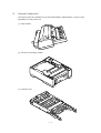
1.2
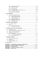
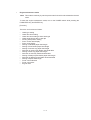
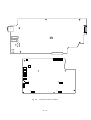
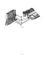
Printer Configuration
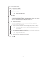
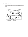
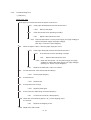
The printer unit consists of the following hardware components:
•
Electro-photographic processor
•
Paper feeder
•
Controller
•
Operator panel
•
Power/sensor board
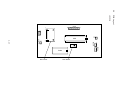
Figure 1-2 shows the printer unit configuration.
Plate-Shield
Frame-OP panel Assy
Cover-Side(I/F)
Stacker Assy
Cover-Frame
Face-up stacker Assy
Cover-Rear
Heat Assy
Cover-Side(R)
Manual Feed Assy
Contact Assy
Cover-Side(L) Assy
I/D Unit
Base Unit
Figure 1-2
1-2
1.3
Optional Configuration
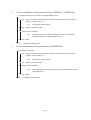
The options below are available for use with OKIPAGE20 / OKIPAGE20n. They are sold
separately from the printer unit.
(1) Multi Feeder
(2) Second/ Third Paper Feeder
(3) DUPLEX Unit
1-3
(3) D-RAM SIMM module (72 pin SIMM, 4 MB/8 MB/16 MB/32 MB)
(4) Flash ROM module (72 pin SIMM, 4MB/8MB)
(5) PostScript ROM module (72pin SIMM)
1-4
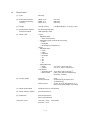
1.4
Specification
(1) Type
Desk top
(2) External dimensions
(excludes protruding
Portion)
Height 13.0”
Width 14.4”
Depth 18.2”
(331 mm)
(366 mm)
(462 mm)
(3) Weight
19.0 kg (42 lbs)
If Installed Duplex 21.3 kg (47 lbs)
(4) Development method
Exposure method
Dry electrophotography
LED stationary head
(5) Paper used
<Type>
• Standard paper
– Xerox 4200 (20 lbs)
• Application paper (manual face-up feed)
– Label
– Envelope
– OHP paper (Transparency)
<Size>
• Standard sizes
– Letter
– Legal
– Executive
– Envelope
– A4
– A5
– B5
– A6
• Applicable sizes
– Width:
3.4” to 8.5” (86 to 216 mm)
– Length:
5.5” to 14” (140 to 355.6 mm)
<Thickness>
– Automatic feed: 16 to 28 lbs (60 to 105 g/m2)
– Manual feed:
Label, OHP paper (transparency)
Envelope, 16~36 lb
(6) Printing speed
First print:
Continuous print:
Warm-up time:
8 sec.
20 sheets/min.[at duplex print :
10 sheets/min]
90 sec. [at room temperature 77˚F
(25˚C) and rated voltage (120 VAC)]
(7) Paper feed method
Automatic feed or manual feed
(8) Paper delivery method
Face down/face up
(9) Resolution
600 x 600 dots/inch
600 x 1200 dots/inch
(10) Power input
120 VAC + 5.5%, –15% (ODA)
230 VAC + 10%
1-5
(11) Power consumption
Peak:
Typical Operation:
Idle:
Power save mode:
Approx. 820W
Approx. 350W
Approx. 95W
Approx. 25W
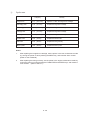
(12) Temperature and humidity
In operation
Power off mode
During Storage
Unit
50 - 90
(10 - 32)
32 - 110
(0 - 43)
14 - 110
(–10 - 43)
°F
(°C)
20 - 80
10 - 90
10 - 90
%RH
Maximum wet
bulb temperature
77
(25)
80.4
(26.8)
°F
(°C)
Minimum difference
of wet and dry
bulb temperatures
35.6
35.6
°F
(2)
(2)
(°C)
Temperature
Humidity
Notes:
1. Storage conditions specified above apply to printers in packed condition.
2. Temperature and humidity must be in the range where no condensation
occurs.
Temperature
(°C)
32
28
Operation range
10
20
(13) Noise
80
During operation:
At standby:
Power save mode:
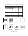
(14) Consumables
Humidity (%)
50 dBA or less (without second tray)
55 dBA or less (with second tray)
45 dBA or less
43 dBA or less
Toner cartridge kit
5,000 pages(5% duty)*
Image drum cartridge 30,000 pages(at continuous Simplex printing)*
19,000 pages(3 page/job)(Simplex printing)*
* Simplex printing without Power Save.
1-6
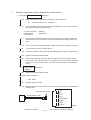
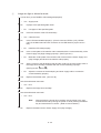
1.5
Safety Standards
1.5.1
Certification label
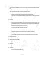
The safety certification label is affixed to the printer in the position below.
ex. ODA 120V
1.5.2
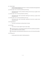
Warning label
The warning label is affixed to the portion which may cause an injury to human body.
Follow the instructions on warning labels during maintenance.
1-7
2.
OPERATION DESCRIPTION
2.
OPERATION DESCRIPTION
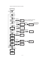
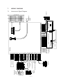
OKIPAGE20 / OKIPAGE20n consists of a main control board, a power supply unit (120V/230V),
a power supply unit (high voltage), an operator panel and an electro-photographic process
mechanism.
The control board receives data through a host I/F, decodes and edits the data, and stores the
edited data in a memory. After completing edition of one page of data, it references the font
memory and generates bit data on the same memory. At the same time, it transfers the bit image
data to an LED head in units of one dot line.
The electro-photographic process mechanism prints data on paper.
The operator panel is used for operations and status display.
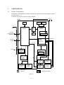
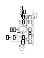
Fig. 2-1 shows an OKIPAGE20 / OKIPAGE20n block diagram.
2-1
MAIN BOARD (BOARD-AAA)
FLASH ROM
Module
or
DUPLEX unit
PS ROM
Module
MULTI feeder
2nd tray
ROM
3rd tray
Paper end sensor
Extension
DRAM
Module
Paper near end sensor
LSI
BOARD PXC
DRAM
Centronics
I/F
7407
RS232C
I/F
TRANSISTOR
CL
Clutch for
Regist Roller
TRANSISTOR
CL
Clutch for
Hopping Roller
DRIVER
M
Hopping Motor
DRIVER
M
Main Motor
CPU
75188
OKI
HSP I/F
Board
(Option)
LAN etc.
(Option)
Tray size
sensor board
Operator panel
EEPROM
LED HEAD
3V 5V +8V -8V 38V
Inlet sensor1
POWER
SUPPLY
UNIT
(AC120V/230V)
paper sensor
Inlet sensor2
Toner sensor
Outlet sensor
LSI
LOW VOLTAGE
GENERATION
CIRCUIT
THERMISTOR
0V
COVER
OPEN
SW
Sub-CH
SUB CHARGE ROLLER
CH
DRIVER
HIGH
VOLTAGE
CIRCUIT
DRIVER
FILTER CIRCUIT
POWER
SUPPLY
UNIT
(high voltage)
CHARGE ROLLER
TR
DB
SB
TRANFER ROLLER
DEVELOPPING ROLLER
TONER SUPPLY ROLLER
CB
CLEANING ROLLER
AC120V/230V
FAN
HEATOR
Figure 2-1 OKIPAGE20 / OKIPAGE20n block diagram
2-2
2.1
Main Control Board (BOARD-AAA)
The control board consists of an one chip CPU,a LSI, program/font ROM's, DRAM's, an
EEPROM, a host interface circuit, and a mechanism driving circuit.
(1) One-chip CPU
The one-chip CPU is a custom CPU (32-bit internal bus, 32-bit external bus, 40-MHz clock)
that incorporates an RISC CPU and its peripheral devices, and has the following functions.
Built-in device
Function
Chip select controller
Bus controller
DRAM controller
Control of peripheral LSI, ROM, DRAM and I/O device
DMA controller
Transfer of data from Host I/F to RAM
Serial interface controller
Control of RS232C serial interface
Parallel interface controller
Control of Centronics parallel interface
Timer
Generation of various control timing
Monitoring of paper running and paper size
Serial I/O port
Control of serial interface between controller and operator panel, EEPROM
Control of a serial interface between controller and power supply board
I/O port
Inputting of various sensor signals
Outputting of various control signals
Motr driver controller
Control of Main Motor
Compression/extension circuit
Compressed frame buffer is produced by compressing the data of temporary
band buffer.
Extension printing operation is executed by extending the data of
compressed frame buffer
(2) Program/font ROM's
The program/font ROM's store the HP LJ5 emulation program and various types of font.
MASK ROM is used as the program/font ROM's.
2-3
(3) DRAM's
4-Megabyte DRAM (16 Mbit DRAM x 2) is mounted as resident memory to be used for storing
the program and providing various buffers. This DRAM is expandable up to 68 Mbytes by
adding expansion memory (SIMMs). This DRAM provides the areas shown in the following
table.
Memory area
Use
Memory capacity setting
MENU
Expansion RAM
System area
Working area used for the program
Fixed
Fixed
Raster buffer
Stores converted bit image data
Enable
Expandable
Receive buffer
Stores temporarily the data received
from the host interface
Enable
Expandable
Page buffer
Adds print information to the analyzed
receive data and stores the resulted
data.
–
Expandable
DLL/macro buffer
Stores soft fonts and macro data.
–
Expandable
Font cache buffer
Stores bit map fonts generated by the
font rasterizer based on scalable font
information
Enable
Expandable
(4) EEPROM
The EEPROM has a 1-kbit capacity and stores the following data.
•
•
•
Menu data
Various counter data (page counter, drum counter, fuser counter, etc.)
Adjustment parameters (LED head drive time, print start position, etc.)
(5) LSI (LZ9FF22)
Built in device
Function
Serial I/O port
Control of serial interface between controller and 2nd tray, 3rd tray, Multi purpose feeder
Control of serial interface between controller and Duplex unit
Motor driver controller Control of Hopping motor
I/O port
Inputting of various sensor signals
Outputting of various control signals
(6) Host interface
This printer has the following interfaces to the host.
•
•
•
Centronics bidirectional parallel interface
RS232C interface
OKI HSP interface (Option)
The single effective interface or the automatic interface select mode can be selected using
the menu. If the busy state of the printer continues for a long time period, the buffer nearfull control releases the busy status at constant intervals even if the host side is busy so not
to cause the interface time-out at the host side.
2-4
(a) Centronics bidirectional parallel interface
This is an interface conforming to IEEE-1284 and provides either of unidirectional and
bidirectional communications according to each of the following communication modes.
•
Compatibility mode
Unidirectional communications from the host to the printer.
•
Nibble mode
This mode transmits 4-bit wide data from the printer to the host. In this mode, each
1-byte data is transferred in the form of two nibbles using ERROR, BUSY, FAULT,
and SELECT signal leads. This mode can provide the bidirectional operation in
combination with the compatibility mode.
•
ECP mode
This mode provides the asynchronous bidirectional interface and transmits and
receives 1-byte data using eight data signal leads under the semi-duplex control by
the host.
When the power is turned on, the compatibility mode is automatically selected. The
change to another mode from the compatibility mode is made through negotiation.
(When the BI DIRECTION is set to ENABLE in the menu, this change can be performed.)
(For the electrical/physical characteristics of this interface, see APPENDIX B)
(b) RS232C serial interface
The following protocol is supported for the serial interface conforming to EIA RS232C.
•
•
•
READY/BUSY (DTR HI or DTR LO)
X-ON/X-OFF
RBST X-ON
(For the electrical/ physical characteristics of the interface, see APPENDIX B)
(c) OKI HSP interface (Option)
This interface (slot) is an OKI unique universal interface that provides the platform to
connect various of boards (including those supplied by third venders) such as the LAN
connection expansion board and SCSI expansion board.
Any expansion boards compatible with this interface can be mounted on the Control
board in the piggyback board from without modifying the program at the printer side. The
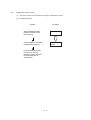
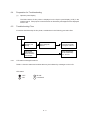
conceptual diagram of the OKI HSP interface is shown in Fig. 2-2.
(For the electrical/physical characteristics of the OKI HSP interface, see the OKI HSP
interface technical manual.)
Printer
Network, etc.
Control board
LAN
expansion board
OKI HSP
interface
Fig. 2-2
2-5
(7) RAM module
•
Pin layout
1
•
36
37
72
Basic specificaton
- Type:
72 pins Standerd SIMM (32 bits buss width)
[Note : EDO SIMMtype cannot be used.]
- Access time:
60ns, 70ns, 80ns, 100ns
- Capacity:
4, 8, 16 or 32MB
- Parity:
None
(8) Flash ROM module
•
Pin layout
Board-FSL
1
•
36
37
72
Basic specificaton
- Type:
72 pins SIIM (32 bits buss width)
- Access time:
90ns
- Capacity:
4 or 8MB
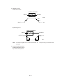
(9) PS ROM module
PS ROM module is BOARD-MSM or BOARD-FSL
BOARD MSM consists of MASK ROM
BOARD FSL consists of Flash ROM (8MB).
•
Pin layout
BOARD-MSM
or
BOARD-FSL
•
•
1
36
37
72
Basic specificaton
- Type:72 pins SIIM (32 bits buss width)
- Access time: 100ns (Board-MSM), 90n (Board-FSL)
- Capacity:
6MB (Board-MSM), 8MB (Board-FSL)
Emulation :
Pstscript Level 2
2-6
2.2
Power Supply Unit
The power supply unit consists of an AC filter circuit, a low voltage power supply circuit, a high
voltage power supply circuit, heater drive circuit, and photosensors.
(1) Low voltage power supply circuit
This circuit generates the following voltages.
Output voltage
Use
+5 V
Logic circuit supply voltage
+30 V
Motor and fan drive voltage and source voltage for high-voltage supply
+8 V
Reset circuit, RS232C Line voltage
–8 V
RS232C Line voltage
+3.8V
LED HEAD supply voltage
(2) High voltage power supply circuit
This circuit generates the following voltages necessary for electro-photographic processing
from +30 V according to the control sequence from the control board. When cover open state
is detected, +30 V supply is automatically interrupted to stop the supply of all the high-voltage
outputs.
Output
Voltage
Use
Sub-CH
-15 µA
Voltage applied to Sub charging roller
CH
-1.30 KV
Voltage applied to charging roller
DB
-220 V/+300 V
Voltage applied to developing roller
SB
-450 V
Voltage applied to toner supply roller
TR
+4 KV/-1.3 kV
Voltage applied to transfer roller
CB
+450 V/-1350V
Voltage applied to clearimng roller
Remarks
Variable + Only
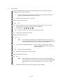
(3) Photosensor
The photosensor mounted on this power supply unit supervises the paper running state
during printing.
2-7
Figure 2-3 shows the sensor layout diagram.
Paper running direction
Roller-exit
Roller-feeder (c)
Outlet sensor
Roller-Heat
Roller-transfer
Paper sensor
Toner sensor
Roller-regist
Inlet sensor 1
Inlet
sensor 2
Feed roller
Figure 2-3
Sensor
Function
Sensing state
Inlet sensor 1
Detects the leading part of the paper and gives the supervision
timing for switching from hopping operation to feeding operation.
Supervises the paper running state and the paper size according to the paper reach time and running time.
ON: Paper exists.
OFF: No paper exists.
Inlet sensor 2
Detects the form width.
ON: A4 or larger
OFF: Smaller than A4
Paper sensor
Detects the leading part of the paper.
Supervises the paper running state.
ON: Paper exists.
OFF: No paper exists.
Outlet sensor
Supervises the paper feed and size according to the time of
arrival to the sensor and the time of passage of paper.
ON: Paper exists.
OFF: No paper exists.
Toner low sensor
Detects the lack of toner.
ON long:
OFF short:
2-8
Toner low exists
No Toner low exists
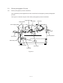
2.3
Electro-photographic Process
2.3.1
Electro-photographic process mechanism
This mechanism prints image data from the control board on the paper by electro-photographic
process.
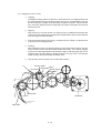
The Figure 2-4 shows the layout of the electro-photographic process mechanism.
Image Drum Unit
LED HEAD
Hopping Motor
Heat Assy
Front Hopping Roller
Face Up stacker
Front Feeder
Roller Assy-Feed
1st Hopping Roller
Motor-Main
Sub Roller
Figure 2-4
2-9
(1) Image drum unit
The image drum unit consists of a sensitive drum, a charger, and a developer. The unit forms
a toner image on the sensitive drum, using a electrostatic latent image formed by the LED
head.
(2) Hopping motor
This motor is a pulse motor of 48 steps/rotation that is two-phase excited by the signal from
the control board. It drives the hopping roller of the first tray and the front feed roller via two
one-way clutches according to the direction of rotation.
(3) Motor-Main
This motor is a pulse motor of 72 steps/rotation that is two-phase excited by the signal from
the control board and is the main motor of this mechanism.
(4) Clutch (for Roller-Regist)
(5) Clutch (for Feed Roller)
(6) LED head
Image data for each dot line from the control board is received by the shift register and latch
register. The 4992 LEDs are driven to radiate the image data to the image drum.
(7) Fuser
The fuser consists of a heater, a heat roller, a thermistor and a thermostat.
An AC voltage from the power supply board is applied to the heater under the control of the
HEATON signal from the control board. This AC voltage heats the heater. The control board
supervises the heat roller temperature via the thermistor, and regulates the heater roller at
a predetermined temperature (185 °C : Normal paper, MEDIA TYPE = MEDIUM) by
connecting or disconnecting the AC voltage supply to the heater.
If the heater roller temperature rises abnormally, the thermostat of the heater voltage supply
circuit is activated to cut the AC voltage supply forcibly.
2 - 10
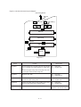
2.3.2
Electro-photographic process
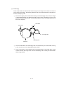
The electro-photographic processing is outlined below. Figure 2-5 shows the electro-photographic printing process.
1 Charging
The surface of the image drum is uniformly charged with negative charges by applying a
negative voltage to the charge roller.
2 Exposure
Light emitted from the LED head irradiates the negatively charged surface of the image drum.
The surface potential of the irradiated part of the image drum surface is lowered, so that an
electrostatic latent image associated with the print image is formed.
3 Developing and toner recovery
When the negatively charged toner is brought into contact with the image drum, it is attracted
to the electrostatic latent image by static electricity, making the image visible.
At the same time, the residual toner on the image drum is attracted to the developing roller
by static electricity.
4 Transfer
When paper is placed over the image drum surface and a positive charge, opposite in polarity
to the toner, is applied to the reverse side of the paper from the transfer roller, the toner is
attracted by the positive charge and is transferred to the paper. As a result, the toner image
formed on the image drum is transferred to the paper.
5 Temporary cleaning
Residual toner that remains on the image drum without being transferred is made uniform
by the cleaning roller and is temporarily attracted to the cleaning roller by static electricity.
6 Fusing
The toner image transferred to the paper is fused under heat and pressure.
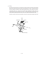
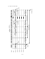
Figure 2-6 shows an electro-photographc process timing chart.
2 - 11
Figure 2-5
2 - 12
(Face up)
Paper
eject
Paper
eject
roller
Paper eject
Cleaning
Fusing pressure
Cleaning
roller
Fusing
Fusing
Heater roller
Outlet sensor
Paper
path
selector
Power
supply
Charger
roller
Power
supply
(Face down)
Paper
eject
Paper
eject
roller
Power
supply
Transfer
roller
Transfer
Transfer
Cleaning
Charging
Exposure
LED head
Image data
Image
production
developing
Paper sensor
Developing
Paper feed
Registration
roller
Paper
registration
Developing
roller
Power
supply
(Bias voltage)
Paper
supply
Direction of
rotation of the
image drum
Path of paper
feeding
Paper hopping
Hopping
roller
Inlet sensor
Doctor
blade
Front
feeder
Toner
supply roller
Toner
cartridge
Figure 2-6
2 - 13
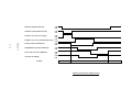
DMON-N (DRUM MOTOR)
OFF
ON
HMON-N (HOPPING MOTOR)
OFF
ON
PWM1-P (CLUCH for hopping)
ON
OFF
PWM2-P (CLUCH for REGISTRATION)
ON
OFF
PSIN1-N (INLETSENSOR1)
OFF
ON
WRSENSE-N (PAPER SENSOR)
OFF
ON
PSOUT-N (OUTLET SENSOR)
OFF
ON
STB-N (LED HEAD)
OFF
ON
PAPER
PAPER TRAY
PRINTER
SIMPLEX PRINTING TIMING CHART
STACKER
Figure 2-7
2 - 14
DMON-N (DRUM MOTOR)
OFF
ON
HMON-N (HOPPING MOTOR)
OFF
ON
PWM1-P CLUCH for hopping)
ON
OFF
PWM2-P (CLUCH for REGISTRATION)
ON
OFF
PSIN1-N (INLETSENSOR1)
OFF
ON
WRSENSE-N (PAPER SENSOR)
OFF
ON
PSOUT-N (OUTLET SENSOR)
OFF
ON
STB-N (LED HEAD)
OFF
ON
DUPMON-N (MAIN MOTOR in DUPLEX
UNIT)
OFF
ON
CLON-P (CLUCH in DUPLEX UNIT)
ON
OFF
SLON-P (SOLENOID in DUPLEX UNIT)
ON
OFF
DUPINSNS-N (INLET SENSOR in
DUPLEX UNIT)
OFF
ON
OFF
DUPRSNS-N (REAR SENSOR inDUPLEX ON
UNIT)
OFF
DUPFSNS-N (FRONT SENSOR in
ON
DUPLEX UNIT)
PAPER
PAPER
TRAY
PRINTER
PRINTER/
DUPLEX UNIT
DUPLEX UNIT
DUPLEX UNIT/ PRINTER
PRINTER
DUPLEX PRINTING TIMING CHART
STACKER
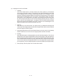
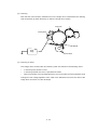
2.4.3
Process operation descriptions
(1) Hopping
Hoppings from the first tray and the front feeder are effected by a single hopping motor in the
mechanism shown below.
Hopping Motor
Front Feeder
1st Tray
Turning the Hopping motor in direction a (CW) drives the 1st Hopping Roller. Turning the
Hopping motor in direction b (CCW) drives the Front Hopping Roller. Gear C and Hopping
roller bult in one-way bearing, so that turning each of these gears in reverse direction will not
be transmitted to the corresponding roller.
a
Gear C
(One-way Clutch build-in )
(CW)
b
Hopping Motor
(CCW)
Inlet Sensor
Front Hopping Roller
(One-way clutch build-in)
Roller-Regist
Planet Gear
Gear B
Sub Roller
1st Hopping Roller
(One-way clutch build-in)
2 - 15
Gear A
Paper
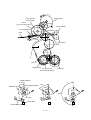
(a) Hopping from the 1st Tray
1 Hopping
Rotating the Hopping Motor in direction a (CW) drives the 1st Hopping Roller and
the Sub Roller then pick up a sheet of paper in the 1st tray. The Main Motor is always
driven in direction c (CCW) on printing. After the paper fed approx. 30mm from the
tray, the Clutch (Feed) drives the Align Roller to advance the paper until the Inlet
Sensor turns off.
2 Aligning
After turning on the Inlet Sensor, the paper fed by a predetermined length and
choked up to the wedge space formed by the Regist Roller and the Pressure Roller
so that to align the skew of paper.
3 During the paper fed from the 1st tray, the build in clutch of Gear C is idled and not
to drive the Front Hopping Roller.
4 Feeding
After aligned the paper, the Hopping Motor turned off and stop hopping. Also the
Clutch (Feed) turned off and the Align Roller idled freely. Then Clutch (Regist)
turned on and the Regist Roller start to feed the paper. After the paper fed, the 1st
Hopping Roller is freely idled by releasing build in one way clutch, also the Sub
Roller is freely idled by escaping the Planet Gear.
5 Start printing. after the paper turns off the Write Sensor.
Pressure Roller
Regist Roller
Inlet Sensor
Gear E
Clutch (Regist)
Write Sensor
c
Clutch (Feed)
Gear D
Main Motor
Align Roller
2 - 16
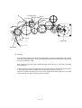
(b) Hopping from the Front Feeder
1 Hopping
The Front Feeder Plate is normally locked at the lower position by the Release
Lever and turn the Micro SW on. Top of the FF Cam which attached on end of the
Front Hopping Shaft is normally located Upper position (0 to 30 degree : home
position). Rotating the Hopping Motor in direction b (CCW) drives the Front Hopping
Shaft and then attached the FF Cam and the Front Hopping Roller are driven.
During the FF Cam rotated approx. 60 degree, the Release Lever was pushed and
the Front Feeder Plate lifts up, then the Front Hopping Roller picks up a sheet of
paper. At the FF Cam rotated approx. 180 degree, the Front Feeder Plate is pushed
down and locked by the Release Lever again. At the FF Cam rotated approx. 275
degree the paper fed until the Inlet Sensor turns off.
2 Aligning
After turning on the Inlet Sensor, the paper fed by a predetermined length and
choked up to the wedge space formed by the Regist Roller and the Pressure Roller
so that to align the skew of paper.
3 During the paper fed from the Front Feeder Plate, the one way clutch of 1st Hopping
Roller is idled and not to drive the 1st Hopping Roller and the Sub Roller.
4 Feeding
After aligned the paper, the Hopping Motor turned off and stop hopping. Then Clutch
(Regist) turned on and the Regist Roller start to feed the paper. After the paper fed,
the Front Hopping Roller drives the Front Hopping Shaft and attached the FF Cam
with small idle torque of build in one way clutch and when comes into the Release
Lever, the one way clutch is slipped and the FF Cam is stopped at the upper position
(home position). The Front Hopping Roller continuously idled up to the paper away.
5 Start printing. after the paper turns off the Write Sensor.
2 - 17
Hopping Motor
Hopping Roller
(Front Feeder)
Gear C
(one way clutch build in)
b (CCW)
Pressure Roller
Front Feeder Plate
Inlet Sensor
Paper
Regist Roller
Paper
d
Gear A
Hopping Roller
1st Hopping Gear
(One way Gear build in)
Sub Roller
(home position)
0~30°
Release Lever
Front Hopping Shaft
60°
180°
FF Cam
Micro SW
Front Feeder Plate
2 - 18
Pressure Roller
Regist Roller
Inlet Sensor
Gear E
Clutch (Regist)
Write Sensor
c
Clutch (Feed)
Gear D
Main Motor
Align Roller
(2) Feeding
After the end of hopping, the pulse motor dedicated for driving the registration roller rotates
to drive the registration roller. The driven registration roller advances the paper until it comes
out of the registration roller.
When leading edge of the paper causes the paper sensor to turn on, the printing is started
synchronously.
Although Gear D is always rotating due to an all-time rotation of the main motor in direction
c, the regist roller would not rotate because the clutch (regist) is turned off.
After the completion of hopping, turn on the clutch (regist) to drive the regist roller. The regist
roller would drive a paper until the paper has passed.
2 - 19
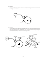
(3) Charging
Charging is effected by applying a DC minus voltage to the charge roller that is in contact with
the image drum surface.
Power
supply
Charge roller
Image drum
(4) Exposure
Light emitted from the LED head irradiates the image drum surface with negative charges.
The surface potential of the irradiated part of the image drum drops, thereby forming an
electrostatic latent image associated with the image signal.
LED head
Charge roller
LED head
Power
supply
Image drum
Paper
2 - 20
Image drum
(5) Developing
Toner is attracted to the electrostatic latent image on the image drum surface to convert it
into a visible toner image. Developing takes place at the contact between the image drum
and the developing roller.
1 As the toner supply roller rotates while rubbing on the developing roller, a friction charge
is generated between the developing roller and the toner, allowing the toner to be
attracted to the developing roller. (The developing roller surface is charged positive and
the toner, negative.)
Doctor blade
Charge roller
Toner supply roller
Developing roller
Image drum
2 The toner attracted to the developing roller is scraped off by the doctor blade, forming
a thin coat of toner on the developing roller surface.
3 Toner is attracted to the exposed part (low-potential part) of the image drum at the
contact between the image drum and the developing roller, making the electrostatic
latent image visible.
2 - 21
(6) Transfer
The transfer roller is composed of conductive sponge material and is designed to make the
image drum surface and the paper closely into contact.
Paper is placed over the image drum surface, and a positive charge, opposite in polarity to
the toner, is applied to the paper from its reverse side.
The application of a high positive voltage from the power supply to the transfer roller causes
the positive charge induced to the transfer roller surface to be transferred to the paper at the
contact between the transfer roller and the paper. As a results, toner charged negative that
is attracted to the image drum surface is transferred to the upper side of the paper by the
positive charge on the lower side of the paper.
Image drum
Paper
Transfer roller
Power
supply
2 - 22
(7) Fusing
After the end of the transfer, the unfused toner image is fused on the paper under heat and
pressure as it passes between the heater roller and the back-up roller. The heater roller with
a Teflon coating incorporates a 750W heater (Halogen lamp), which heats the heat roller.
A thermistor which is in contact with the heater roller regulates the heater roller at a
predetermined temperature (about 180 ~ 200°C). A safety thermostat cuts off voltage supply
to the heater by opening the thermostat in the event of abnormal temperature rises.
The back-up roller is held under a pressure of 5 kg from the pressure spring at each side.
Heater
Thermistor
Separation Claw
Heater Roller
Paper
Roller-BK
Pressure Spring
2 - 23
(8) Cleaning
After the end of the transfer, residual toner on the image drum is attracted to the cleaning
roller temporarily by static electricity to clean the image drum surface.
Image Drum
Cleaning Roller
Power
Supply
Transfer Roller
(9) Cleaning of rollers
The charge roller, transfer roller and cleaning roller are cleaned in the following cases:
•
•
•
In warming up at power-on time
In warming up after the cover is opened and closed
When the number of accumulated sheets is 10 or more and the printout operation ends
Changes in bias voltage applied to each roller move adhesive toner from the roller to the
image drum and return it to the developer.
2 - 24
2.3.4
Revision of LED Head Illumination
An LED correcting head, which is capable of correcting the illumination of the LED for each dot,
is being used in this printer. LED illumination correction function of 16 steps is carried out by using
an EEPROM which is installed in the LSI that maintains the LED illumination correction values,
and an LED correction drivers together as a pair.
The LED correcting head consists of the correction control LSI , LED drivers , and an LED array.
The block diagram of the LED correcting head is shown below.
Correction Control
LSI
EEPROM
STRB4-N
STRB3-N
DATA 3
DATA 2
LED Driver
LED Driver
LED Array
From
CPU
LOAD
CLOCK
STRB2-N
STRB1-N
DATA 1
DATA 0
LED
LED
LED Driver
LED
LED
LED
LED
LED
LED Driver
The LED correcting head is a 600 dpi head, with the LED drivers located on both sides of the LED
array with a 300 dpi pitch spacing. The printing and correction data obtained from the CPU
through four signal lines are sent to the LED array.
In OKIPAGE 20/ OKIPAGE 20n, the correction control of LED head is excuted direction by CPU.
The procedure is as follows
(1) LED head is set to the correction control read mode and all correction data stored in EEPROM
within the correction control LSI are read by CPU, and stored temporarily in the memory.
(2) Next, LED head is set to the correction control direct mode and the correction data stored
temporarily in the memory is transferred directly to the LED driver.
2 - 25
STRB4-N
STRB3-N
STRB2-N
STRB1-N
DATA 3~0
LOAD
CLOCK
2 - 26
RD Mode set
Mode setting
RD
1 0 0 0
8 clocks
dummy cycle
High-Z
RD cycle
8 clocks
Correction data read
correction data
correction data
RD cycle
Total 19992 clocks
data4
data3
8 clocks
8 clocks
Head data read
RD cycle
data2
data1
250ns min
RD Mode enabled
8 clocks
RD cycle
correction data 4992
correction data 4992-1
High-Z
(1) Read of correction data
STRB4~1
DATA 4~1
LOAD
CLOCK
2 - 27
1 0
DIRECT
1
0
Correction data 4
Correction data 2
DIRECT Mode set
Mode setting
0
Correction data 1
Correction data 3
Total 2496 clocks
250ns min
DIRECT Mode enabled
Correction data 4992
Correction data 4991
(2) Transfer of correction data to head driver correction data
The LED driver corrects the LED illumination by controlling the LED current. The LED illumination
can be set in 16 steps, with 7 steps in the direction of illumination increase in relation to the
standard value, and 8 steps in the direction of decrease. For this reason, the LED correction data
is a 4-bit data for each dot.
The relationship between the LED correction data and LED current correction steps with the LED
driver used in an LED head is shown below.
LED Correction Data
Corretion Data
Correction
Step
Correction
Mode
msb b3
b2
b1
lsb b0
1
0
0
0
+16%
↑
0
1
1
1
+14%
↑
0
1
1
0
+12%
Correction by
0
1
0
1
+10%
increasing
0
1
0
0
+8%
illumination
0
0
1
1
+6%
↑
0
0
1
0
+4%
↑
0
0
0
1
+2%
↑
0
0
0
0
0%
No correction
1
1
1
1
-2%
↓
1
1
1
0
-4%
↓
1
1
0
1
-6%
Correction by
1
1
0
0
-8%
decreasing
1
0
1
1
-10%
illumination
1
0
1
0
-12%
↓
1
0
0
1
-14%
↓
2 - 28
The printing operation timing chart is shown below.
Normal Mode Printing Timing Chart
CLOCK
LOAD
DATA3~0
STRB1-N
STRB2-N
STRB3-N
STRB4-N
First line printing data sent
Second line printing data sent
First line printing
The printing operation is carried out in normal mode. Under ordinary circumstances such as when
the power is turned on or when LOAD signal level is low, the normal mode is enabled.
The printing operation is carried out in the following sequence. First, the printing data DATA3
through DATA0 are stored, sequentially shifted, in the shift registers of the LED drivers, by the
printing data synchronous clock, CLOCK. Then the printing data stored in shift registers are
latched by the high level pulse of LOAD. The latched printing data turns the LEDs on by STRB1N through STRB4-N and actuates printing.
2 - 29
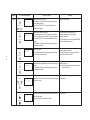
2.4
Paper Jam Detection
The paper jam detection function supervises the paper state at power-on time and during printing.
In the event that the following state occurs, this function interrupts the printing process. If any of
the following errors is presented, recovery printing will be performed by removing the jammed
paper (namely by opening the upper cover, removing the jammed paper and closing the upper
cover).
Error
Paper input jam
Cause of error
• At power-on time, the paper is placed at the inlet sensor.
• After hopping operation is attempted three times, the leading part of the
paper does not reach the inlet sensor.
Paper feed jam
• At power-on time, the paper is placed at the paper sensor.
• The leading part of the paper does not reach the paper sensor within a
predetermined distance after the paper has reached the inlet sensor.
• The traiding part of the paper does not pass over the paper sensor within
a predetermined distance after the leading edge of the paper has passed
over the paper sensor.
• The leading part of paper does not reach the outlet sensor within a
predetermined distance after the paper has reached the paper sensor.
Paper exit jam
• At power-on time, the paper is placed on the outlet sensor.
• The paper does not pass over the outlet sensor within a predetermined
after the leading part of the paper has reached the outlet sensor.
• The paper size check with the manual feed specified considers the
reference size as free size.
Paper size error
• The size of the paper is supervised by the inlet sensors 1. It is detected
that the paper does not pass over the inlet sensor 1 within predetermined
range of distance.
• The inlet sensor 2 detects that the size of the loaded paper is A4 or larger,
or smaller than A4. The detected paper size differs from the paper size
set by command or menu.
• The paper size check with the manual feed specified considers the
reference size as free size.
2 - 30
2.5
Cover Open
When the stacker cover is opened, the cover open microswitch on the Power Supply Unit (High
voltage) is turned off to cut the supply of +30V to the high voltage power supply circuit. As a result,
all high-voltage outputs are interrupted. At the same time, the CVOPN signal is sent to the control
board to notify it of the off state of the microswitch, and the Main board performs the cover open
processing.
2 - 31
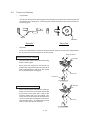
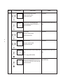
2.6
Toner Low Detection
•
Composition
The device consists of the stirring gear which rotates at a constant rate, the stirring bar and
the magnet on the stirring bar. The stirring bar rotates through the link on the protrusion in
the stirring gear.
Magnet
Protrusion
Stirring Bar
•
Stirring Gear
Operation
Toner Low is detected by monitoring the time interval of the encounter of the magnet set on
the sensor lever and the magnet on the stirring bar.
Stirring Gear Section
Operation during toner full state
Stirring Bar
•
The stirring bar rotates due to the interlocking
with the stirring gear.
•
Even when the magnet on the stirring bar
reaches the maximum height, since the other
side is being dipped in the toner, the stirring
bar is pushed by the stirring gear.
Sensor Lever
Toner Sensor
Stirring Bar
Operation during toner low state
•
When the stirring bar reaches the maximum
height, since there is no resistance provided
by the toner on the other side, it falls to the
minimum height due to its own weight. Because of this, the time interval during which it
is in encounter with the magnet of the sensor
lever becomes long. By monitoring this time
interval, toner low can be detected.
2 - 32
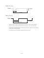
Sensor Lever
TONER FULL state
TNRSNS
t1 < 2.727/4
t1
2.727 SEC.
TONER LOW state
TNRSNS
t1
t1 > 2.727/4
2.727 SEC.
•
When the toner low state is detected 2 times consecutively, Toner Low is established.
•
When the toner full state is detected 2 times consecutively, Toner Low is cancelled.
•
When there is no change with the toner sensor for 2 cycles (2.727 sec. x 2) or more, then the
Toner Sensor Alarm is activated.
•
The toner sensor is not monitored while the drum motor is in halt.
2 - 33
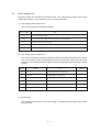
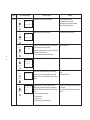
2.7
Stacker-full Detection
The sensor (interlocked with the lever) at the paper outlet to the stacker detects a stacker-full state
(about 250 sheets) and stops printing of the ensuing pages.
2.8
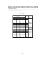
Page Size Detection
The four tab pieces are driven according to the setting position of the paper guide through the cam
interlocked with the paper guide of the paper cassette.
When the paper cassette is inserted into the printer, the state of the tab pieces is detected by the
microswitch to recognize the paper size.
State of Microswitches
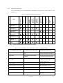
2.9
Paper size
SW1
SW2
SW3
SW4
0
1
1
1
Letter
0
1
0
1
Executive
0
0
1
1
A4
1
1
1
0
Legal 14
1
0
1
1
Legal 13
1
1
0
1
B5
1
1
0
0
A5
1
0
0
1
A6 (Not available)
PostScript ROM module (BOARD-MSM or BOARD-FSL)
PostScript ROM module is mounted on SIMM socket (FSIMM1).
The PostScript ROM module consists of program/font ROM's, an EEPROM.
(1) Program/font ROM's
The program/font ROM's store the PostScript Level II program and its fonts.
BOARD-MSM consists of Mask ROM.
BOARD-FSL consists Flash ROM.
Mask ROM and Flash ROM is used as the program/ font ROM's.
(2) EEPROM
The EEPROM has a 4-kbit capacity and stores the PostScript's menu settings.
(3) Emulation
PostScript Level 2.
2 - 34
3.
PARTS REPLACEMENT
3.
PARTS REPLACEMENT
The section explains the procedures for replacement of parts, assemblies, and units in the field.
Only the removal procedures are explained here. Reverse the procedure for the installation.
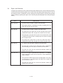
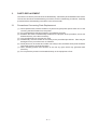
3.1
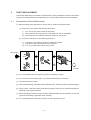
Precautions for Parts Replacement
(1) Before starting parts replacement, remove the AC cable and interface cable.
(a) Remove the AC cable in the following procedure:
i) Turn off ("o") the power switch of the printer
ii) Disconnect the AC inlet plug of the AC cable from the AC receptacle.
iii) Disconnect the AC cable and interface cable from the printer.
(b) Reconnect the printer in the following procedure.
i) Connect the AC cable and interface cable to the printer.
ii) Connect the AC inlet plug to the AC receptacle.
iii) Turn on ("l") the power switch of the printer.
Disconnect
OFF
Connect
ON
(2) Do not try disassembly as long as the printer is operating normally.
(3) Do not remove unnecessary parts: try to keep disassembly to a minimum.
(4) Use specified service tools.
(5) When disassembling, follow the determined sequence. Otherwise, parts may be damaged.
(6) Since screws, collars and other small parts are likely to be lost, they should temporarily be
attached to the orginal positions.
(7) When handling ICs such as microprocessors, ROM and RAM, and circuit boards, do not wear
gloves that are likely to generate static electricity.
(8) Do not place printed circuit boards directly on the equipment or floor.
3-1
[Service Tools]
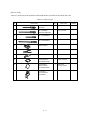
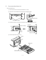
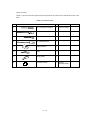
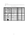
Table 3-1 shows the tools required for field replacement of printed circuit boards and units.
Table 3-1 Service Tools
No.
Service Tools
Q' ty
Place of use
1
No. 1-100 Philips
screwdriver
1
2~2.5 mm screws
2
No. 2-200 Philips
screwdriver, Magnetized
1
3~5 mm screws
3
No. 3-100 screwdriver
1
4
No. 5-200 screwdriver
1
5
Digital multimeter
1
6
Pliers
1
7
Handy cleaner
1
8
LED Head cleaner
P/N 4PB4083-2248P1
1
Cleans LED head
9
Disconnector for
Jack-in connector
P/N 4PP4076-5395P1
1
Disconnect
Jack-in connector
10
For removing
ROLLER-Transfer
P/N 40596701
1
Holder-TR Eject
3-2
Remarks
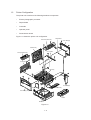
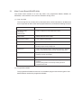
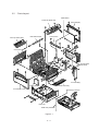
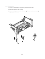
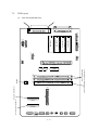
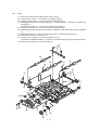
3.2
Parts Layout
Plate-Shield
Frame-OP panel Assy
Cover-Side(I/F)
Face-up stacker Assy
ROLLER-Transfer
Cover-Frame
Cover-Rear
Main Control Board
(Board-AAA)
Cover-Side(R)
Manual Feed Assy
Contact Assy
Cover-Side(L) Assy
Base Unit
CASE Assy-Cassette
Figure 3-1
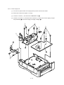
3-3
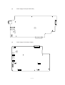
Feed Unit-FRONT
Toner Cartridge
(Type 7)
ID Unit
(Type 7)
HEAT-Assy
Motor-Main
ROLLER
Assy-Feed
FRAME-Main
GUIDE-Assy-Eject
LED HEAD
DC Fan Motor
Stacker Cover
Figure 3-2
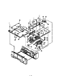
3-4
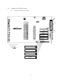
Power Supply Unit (120V/230V)
Power Supply Unit (High Voltage)
FRAME Assy-Hopping
ROLLER Assy-Feed
FILM-Insulation
GUIDE
Assy-Cassette(R)
Board PXC
GUIDE Assy-Cassette(L)
PLATE-Bottom
Figure 3-3
3-5
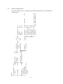
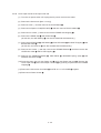
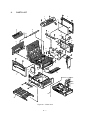
(3.3.4)
(3.3.19)
OP Panel Assy
Paper Cassette,
(3.3.10)
Feeder Unit-Front
Roller Assy-Feed
TR Bearing
Motor-Main
(3.3.17)
(3.3.12)
(3.3.22)
(3.3.13)
(3.3.18)
(3.3.9)
3-6
(3.3.25)
(3.3.26)
(3.3.27)
(3.3.28)
Paper Sensor Lever
Inlet Sensor Lever
Power Supply Unit
Lever-Paper end &
Paper near end
(3.3.24)
Toner Sensor Lever
Lever Assy-Out Sensor (3.3.23)
EP Lock Shaft
Guide Assy-Eject
LED Head
Damper
(3.3.8)
(3.3.11)
Cable Cover
Roller Assy-Regist
(3.3.7)
Sensor Stacker Full
, Cover Rear
(3.3.6)
(3.3.16)
Stacker Assy, Damper Arm
Roller Assy-BK
Transfer Roller/TR Gear/
Frame Assy-Separation (3.3.20)
(3.3.5)
(3.3.14)
HEAT Assy
Board-AAA
(3.3.3)
DC fan motor
ROLLER-Assy-Hopping
(3.3.21)
(3.3.2)
Contact Assy
ROLLER Ass-Feed,
(3.3.1)
Face-up Stacker Assy
Printer Unit
(3.3.15)
Gudie Assy-Cassette(R) (3.3.30)
Gudie Assy-Cassette(L) (3.3.29)
Roller Feed (C)
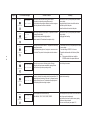
3.3
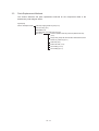
How to Change Parts
This section explains how to change parts and assemblies appearing in the disassembly
diagram below.
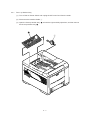
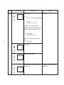
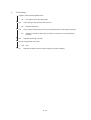
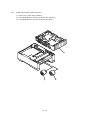
3.3.1
Face -up Stacker Assy
(1) Turn off the AC Power Switch and unplug the AC Power Cord from the outlet.
(2) Disconnect the Interface Cable 1.
(3) Open the face-up stacker assy 2, unhook the right and left projections, and then remove
the face-up stacker assy 2.
2
1
3-7
3.3.2
Contact Assy
(1) Open the stacker assy 1 and unscrew 2 screw 2 to remove the assy -side (L)3.
(2) Unscrew 2 screws 4 and remove the plate (contact) 5 and contact Assy 6.
Note! Don’t deform the electrode plates of the contact assy 6.
2
1
3
Unlock this part before
removing
6
6
5
4
3-8
3.3.3
DC Fan Motor
(1) Remove the cover assy-side (L). [See 3.3.2 (1)]
(2) Remove the DC fan motor 1 by pulling out the connector of DC fan motor 1.
1
3-9
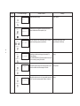
3.3.4
OP Panel Assy
(1) Disconnect the Interface cable 1.
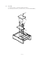
(2) Open the stacker assy 2, unscrew 2 screws 3 and remove the cover side (I/F) 4.
(3) Remove 2 screws 5 and flexible cable 6 to remove the operator panel assy 7.
5
7
6
3
4
1
2
3 - 10
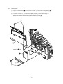
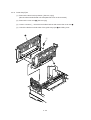
3.3.5
Board-AAA
(1) Remove the operator panel assy and cover side (I/F). [See 3.3.4]
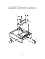
(2) Unscrew 2 screws 1 and remove the cover side (R) 2.
(3) Unscrew 2 screws 3 and remove plate-shield 4.
(4) Unscrew 3 screws 5 and 2 screws 6, unplug all the connectors 7 , and remove Board-AAA
8.
4
6
7
5
3
7
5
5
7
8
1
2
3 - 11
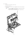
3.3.6
Stacker Assy, Damper Arm, Cover Rear
(1) Remove the face-up stacker assy. [See 3.3.1]
(2) Remove the cover-side (L). [See 3.3.2 (1)]
(3) Remove the OP panel assy. [See 3.3.4]
(4) Remove the Board-AAA. [See 3.3.5]
(5) Loosen 2 screws, unlock the both sides latches and remove the cover rear A.
(6) Unscrew 2 screws 1 and cover frame 2.
(7) Unscrew 3 screws 3 and remove the plate assy-side (R) 4.
(8) Remove the lever back up release 5 and unlock the engagement of the projection on the
right side of gear at the right side of stacker cover.
(9) Remove a screw 6 and washer 7, and then remove the stacker assy 8.
(At this time, the damper arm 9 can also be detached simultaneously.)
8
5
1
2
A
7
6
9
3
0
4
3 - 12
3.3.7
Sensor Stacker Full
(1) Turn the AC power switch off. Unplug the AC power cord from the outlet.
(2) Remove the Stacker assy. [See 3.3.6]
(3) Remove four screws 1. Remove stacker mount 2 by releasing the tabs at position 2A .
(4) Remove Sensor stacker full 3 by releasing speading the plastic tabs on each side of sensor
Assy 3 and lifting switch from cover.
1
2A
1
3
3 - 13
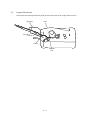
2A
2
3.3.8
Cable cover (guide film)
(1) Turn the AC power switch off. Unplug the AC power cord from the outlet.
(2) Remove the stacker Assy. [See 3.3.6]
(3) Unscrew 2 screws 1 release tabs at portion 1A . Remove cable cover 2, guide film 3.
1A
2
1
3
Note:
Use care when replacing cable cover. Do not pitch, crimp, or cut cables or
protective sheet.
3 - 14
3.3.9
Damper
(1) Remove the damper arm. [See 3.3.6]
(2) Unscrew 2 screws 1 and remove the two damper 2.
1
2
3 - 15
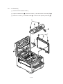
3.3.10 Feeder Unit-Front
(1) Open the manual feed assy 1 and release both right and left parts by pulling out the
engagements on the lower part.
(2) Stand the manual feed assy 1 on end and unhook the engagements with both right and left
manual feed hopper stays.
(3) Remove the OP panel assy. [See 3.3.4]
(4) Unscrew 5 screws 2 and remove the feeder unit-front 3.
2
2
2
3
1
3 - 16
3.3.11
Roller Assy-Regist
(1) Remove the feeder unit-front. [See 3.3.10]
(2) Remove an E-ring 3, gear assy-clutch 4, and four screws 1 in this order, and lifting out the
roller assy-regist 2.
1
2
3
1
4
3 - 17
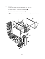
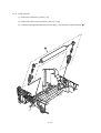
3.3.12 Motor -Main
(1) Remove the stacker assy. [See 3.3.6]
(2) Remove the feeder unit-front. [See 3.3.10]
(At this point, the manual feed assy has not to be removed.)
(3) Remove the DC fan motor. [See 3.3.3]
(4) Remove the contact assy. [See 3.3.2]
(5) Remove the plate-FG (F) 1.
(6) Remove the TR gear 2 and roller transfer 3.
(7) Unscrew 7 screws 4 and remove the main frame 5.
(8) Unlock latches at two points of the lever back up release 6 and pull out it in right direction.
(9) Unhook the EP lock spring 7 and remove the EP lock lever 8.
(10) Take off the E ring 9 and remove the plate-FG (1st ) 0 and gear assy-clutch A.
(11) Unlock 2 latches to remove the motor assy-main B and idle gear C.
(12) Unscrew 2 screws D and remove the motor -main E .
3 - 18
2
3
Latch
8
5
View A
7
6
3
2
E
4
4
4
4
D
B
View A
C D
0
9
A
1
4
4
5
3 - 19
3.3.13 Guide Assy-Eject
(1) Remove the lever back up release. [See 3.3.12(8)]
(But the roller transfer/feeder unit front/plate-FG have not be removed)
(2) Remove the cover rear 2. [See 3.3.6(5)]
(3) Loosen 2 screws 1, unlock the both side’s latches and remove the cover rear 2.
(4) Unlock the latches on both sides of the guide assy-eject 3 and lifting it out.
2
1
1
3
3 - 20
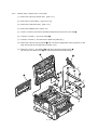
3.3.14 Heat Assy
(1) Remove the cover assy-side (L). [See 3.3.2 (1)]
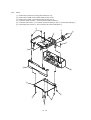
(2) Unplug the connectors 1, 2.
(3) Unscrew 4 screws 3 and remove the heat assy 4 in the direction of the arrow by lifting the
right side first.
Note !
• As the heat assy 4 becomes high temperature soon after the power is turned
off, start the work after it cools off sufficiently.
• Carry out a reset of the counter after the replacement. (See Section 4.2)
3
3
4
2
1
3 - 21
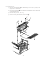
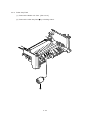
3.3.15
Roller feed (C)
(1) Remove the guide assy-eject. (See 3.3.13)
(But roller transfer/feeder unit-front/plate-FG(F) have not be removed)
(2) Remove the gear roller (C) 1 and bush 2, warp (a) part of the plate-FG (BK) 3. Take off
the carrier bearing 4 and remove the roller feed (c) 5 in the direction of the arrow.
Be careful not to deform (a) part of the plate-FG (BK) 3.
Note !
1
2
5
4
(a)
3
3 - 22
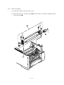
3.3.16 Roller Assy-BK
(1) Remove the heat Assy. [See 3.3.14]
(2) Remove the lever back up release. [See 3.3.12 (8)]
(3) Unlock the engagement with the plate-FG (BK) 1 and lift out the roller heat assy 2.
2
1
3 - 23
3.3.17 Roller Assy-Feed
(1) Remove the feeder unit -front. [See 3.3.10]
(2) Remove the roller assy-feed 1 by unlocking a latch.
1
3 - 24
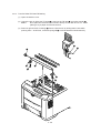
3.3.18 LED Head
(1) Remove the stacker assy 1. [See 3.3.6]
(2) Unplug the PC connector 2 and 2 LED cables 3 from the LED head 4.
(3) Open the hooks of the cover stacker 1 in the direction of the arrow and remove the LED head
4.
(4) Pull out the head spring 5 from the post.
Note: Don't remove two LED cable 3 from the PC connector 2.
1
5
3
2
4
5
3 - 25
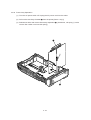
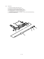
3.3.19 Paper cassette, ROLLER Ass-Feed, ROLLER-Assy-Hoppibg
(1) Pull out the case assy -cassette 1 from the printer.
(2) Remove the ROLLER Ass-Feed 2 and remove the ROLLER-Assy-Hopping 3.
3
2
1
3 - 26
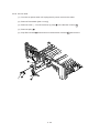
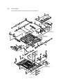
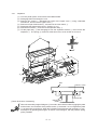
3.3.20 Frame Assy-Separation
(1) Turn the AC power switch off. Unplug the AC power cord from the outlet.
(2) Pull out the case Assy-Cassette 1 from the printer.[See 3.3.19(1)]
(3) Release two locks and remove frame assy-separation 2. (At this time, coil spring 3 is also
remove. Be careful not to lose this spring.)
2
3
1
3 - 27
3.3.21 Transfer Roller/TR Gear/TR Bearing
(1) Open the stacker cover .
(2) Unlock the lock by lifting the TR gear 1 to remove the TR gear 1 and roller transfer 2.
Note !
Don’t place the removed roller transfer directly on the desk and so on. When
placing it, lay a paper and the like under it.
(3) Remove right and left, 2 bearings 3 from the frame-main by sliding them inside while
pushing them. At this time, 2 transfer springs R 4 would be detached simultaneously.
1
2
1
3
2
4
3
4
3 - 28
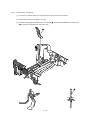
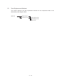
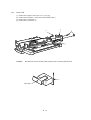
3.3.22 EP lock shaft
(1) Turn the AC power switch off. Unplug the AC power cord from the outlet.
(2) Remove Frame-Main [See.3.3.12(7)]
(3) Remove screw 1. Turn EP lock lever (L) Assy 2 in the direction of arrow A .
(4) Remove spring 3.
(5) Drop EP lock shaft 4 down and turn in the direction of arrows B and remove it.
4
A
B
1 3
2
3 - 29
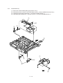
3.3.23 LEVER Assy- Out Sensor
(1) Turn the AC power switch off. Unplug the AC power cord from the outlet.
(2) Remove the frame main [See 3.3.12(7)]
(3) Press the clamp part of LEVER Assy.- Out Sensor 1. Remove the LEVER Assy.-Out Sensor
1 by pushing it upward from the lower side.
1
1
3 - 30
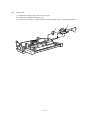
3.3.24 Toner sensor lever
(1) Turn the AC power switch off. Unplug the AC power cord from the outlet.
(2) Remove the frame main [See 3.3.12(7)]
(3) Squeeze the clamp part of toner sensor lever 1 and remove the toner sensor lever 1 by
pushing it upward from the lower side.
1
1
3 - 31
3.3.25 Paper sensor lever
(1) Turn the AC power switch off. Unplug the AC power cord from the outlet.
(2) Remove the frame main [See 3.3.12(7)]
(3) Squeeze the clamp part of the paper sensor lever 1 and remove the paper sensor lever 1
by pushing it upward from the lower side.
1
1
3 - 32
3.3.26 Inlet sensor lever
(1) Turn the AC power switch off. Unplug the AC power cord from the outlet.
(2) Remove the frame main [See 3.3.12(7)]
(3) Squeeze the clamp part of two inlet sensor levers 1. Remove the inlet sensor levers 1
by pushing them downward.
1
1
1
3 - 33
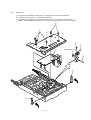
3.3.27 Power supply unit
(1) Turn the AC power switch off. Unplug the AC power cord from the outlet.
(2) Remove the frame main [See 3.3.12(7)]
(3) Unscrew 2 screws 1 and remove the BRACKET-AC 2.
(4) Unscrew 10 screws 3 and remove the connector 6 remove the Power supply unit [ACDC(120/230V)] 4 and Power supply unit (High voltage) 5.
3
3
6
3
3
2
4
5
1
3 - 34
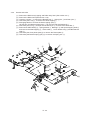
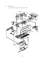
3.3.28 Lever-Paper end & Lever-Paper near end
(1) Turn the AC power switch off. Unplug the AC power cord from the outlet.
(2) Remove the frame main [See 3.3.12(7)]
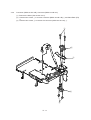
(3) Remove screw 1 and then remove the PLATE-Base 2.
(4) Remove two Spacer-Cord(KGPS-5RF) 4 and then remove FILM-Insulation 4.
(5) Remove four screws 5 and then remove the FRAME ASS-Hopping 6.
(6) Remove the GEAR-Z58 9 and GEAR-Z42 8.
(At this time, the ADF Bearing 0 can also be detached simultaneously.)
(7) Remove the GEAR-Z38 D, ADF Bearing E, ROLLER-Guide F and SHAFT Hopping G and
Bracket-Sub roller R.
(At this time, the Kock Pin H can also be detached simultaneously.)
(8) Remove two screws 7 and then remove the SPRING-Release A and then remove the
LEVER-Sub roller B and PLATE-Hopping C.
(9) Remove the GEAR-Planet(Z28) I, Plate-Planet J, BRACKET-Spring (Sub) K and
SPRING-Sub ROLLER L.
(10) Press the clamp part of Lever-Paper end M and Lever-Paper near end N. Remove the
Lever-Paper end M and Lever-Paper near end N by pushing it upward from the FRAME
Hopping R.
(11) Remove the Connection Cord-Wire O and TR-23-11-14 R CORE P together.
(12) Remove two Photo Sensor Q.
3 - 35
5
8
6
7
5
4
C
1
9
0
P
O
A
Q
HG
B
M
Q
K
3
2
N
L
R
E
J
F
D
I
3 - 36
R
F
3.3.29 Guide Assy-Cassette (L)
(1) Turn the AC power switch off. Unplug the AC power cord from the outlet.
(2) Remove Frame Main [See 3.3.12(7)]
(3) Remove PLATE-Base and FRAME Assy Hopping [See 3.3.28 (5)]
(4) Unscrew two screw 1 and then remove Guid Assy-Cassette (L) 2.
(5) Remove SPRING-Sheet 3 and then remove LINK-Sheet 4 and pull block 5.
(Pay attention the direction of hook of SPRING-Sheet 3.)
(6) Remove spring 6 and then remove cassette stopper 7.
(7) Remove screw 8 from LINK-Sheet 4 and then remove link support 9 and Roller-link 0.
(8) Remove Earth Plate L A and Plate-Earth (link) B.
A
B
5
3
2
6
7
8
0
9
1
3 - 37
4
3.3.30 Guide Assy-Cassette (R)
(1) Turn the AC power switch off. Unplug the AC power cord from the outlet.
(2) Remove Frame Main [See 3.3.12(7)]
(3) Remove PLATE-Base and FRAME Assy Hopping [See 3.3.28 (5)]
(4) Unscrew two screw 1 and then remove Guid Assy-Cassette (R) 2.
(5) Remove SPRING-Sheet 3 and then remove LINK Sheet 4 and pull block 5.
(Pay attention the direction of hook of SPRING-Sheet 3.)
(6) Remove spring 6 and then remove cassette stopper 7.
(7) Remove screw 8 from LINK-Sheet 4 and then remove link support 9 and Roller-link 0.
(8) Unscrew two screws A and remove the Square shaped connector (176496-1) B and
Nylon Connector Cord C and TR-23-11-R CORE D.
(9) Unscrew two screws E and remove the two Plate Earth (Bottom) F.
(10) Unscrew two screws G and remove the Square shaped connector (5-176496-1) H and
Connection Cord Wire I and TR-23-11-R CORE J.
(11) Unscrew a screw K and remove the Detector spring L.
(12) Unscrew a screw M and remove the Board PXC N.
3 - 38
E
E
F
F
5
H
G
J
I
N
2
6
M
7
L
D
3
K
C
4
9
B
8
0
A
1
3 - 39
4.
ADJUSTMENT
4.
ADJUSTMENT
This chapter explains the adjustment necessary when replacing a part. Adjustment is made by
changing a parameter value set in EEPROM on the controller PCB. A parameter is able to set
with the key operation on the operator panel. This printer has three kinds of the maintenance
mode, it is required to select one of the maintenance mode necessary when replacing a part.
4.1
Maintenance Modes And Functions
•
User maintenance mode
To enter the user maintenance mode, turn on the POWER switch while pressing the MENU
key.
[Function]
There are 13 functions as follows.
•
•
•
•
•
•
•
•
Menu reset
Hex dump
Drum counter reset
Resource Save
Receive Buffer Size
Operator panel menu disable
X adjust
•
•
•
•
•
•
Y adjust
Duplex Adjust
Select paper source command parameter
(Second, Third, Front Tray)
Page placement
Setting
Cleaning cycle
System maintenance mode
Note: This mode is used only by service persons and it should not be released to the endusers.
To enter the system maintenance mode, turn on the POWER switch while pressing the
RECOVER key.
[Function]
There are 8 functions as follows.
•
•
•
•
•
•
•
•
•
Page count display
Page count printing enable/disable
Rolling ASCII continus prinitng
RS232C LOOP TEST
EEPROM reset
HSP ERROR recovery
HSP ERROR count display
HSP ERROR count reset
SIDM enable/disable
4-1
•
Engine maintenance mode
Note: This mode is used only by service persons and it should not be released to the endusers.
To enter the engine maintenance mode, turn on the POWER switch while pressing the
FORM FEED key and ENTER key.
[Function]
There are 19 functions as follows.
•
•
•
•
•
•
•
•
•
•
•
•
•
•
•
•
•
•
•
Head type setting
Head drive time setting.
Head drive time setting at Auto head type
Head strobe time at 600 x 1200 dpi
Printing start position setting
Drum counter total display
Drum count display
Setting of standard paper feed length
Setting of front feeder paper feed length
Setting of second tray paper feed length
Selection of second tray feeder download table
Setting of third tray paper feed length
Selection of third tray feed download table
Setting of Multi-purpose feeder paper feed length
Selection of Multi-purpose feeder download table
Setting of duplex feed length
Fuser count indication
Fuser count reset
Engine reset
4-2
4.1.1
User maintenance mode
•
To enter the user maintenance mode, turn the power supply ON while pressing the Menu
key.
•
This mode uses the menu for function selection.
•
The user maintenance mode provides the following functions:
(1)
Menu reset
(2)
(3)
(4)
•
All settings for Menu level-1 are reset to the factory default values.
The menus for all executable emulations including options are reset to the factory
default values.
•
The operation mode starts automatically upon completion of resetting.
Hex dump
•
The data received from the host is dumped in hexadecimal notation to the printer.
•
Printing is activated automatically when the received data exceeds one page. If the
received data is less than one page, printing can be activated manually be pressing the
Form Feed key after selecting the OFF LINE mode by pressing the ON-LINE key.
(Automatic activation of printing even when the received data is less than one page by
selecting the Auto Eject function on the menu.)
•
To exit from this mode is turning the power OFF.
Drum counter reset
•
This function resets the drum life data when the user replaces the image drum unit.
•
The operation mode starts automatically upon completion of resetting.
Resource Save
•
(5)
Receive Buffer Size
•
(6)
This function is for enabling and disabling the operator panel menu functions (Menu 1,
Menu 2, Tray Select, Copies and Paper Size).
X ADJUST
•
(8)
Set the receiving buffer.
Operator panel menu disable
•
(7)
Set the storage area size of resource to be stored between PCL and Postscript.
This function is used to adjust the printing start position within the range of ±2 mm in
0.25 mm steps in the X direction.
Y ADJUST
•
This function is capable to adjust the printing start position within the range of ±2 mm
in 0.25 mm steps in the Y direction.
4-3
(9)
Duplex adjust
•
The function which performs a correction in Y direction towards the sheet supplied from
the tray in double-sided printing.
(10) Select paper source command parameter (Second tray)
•
The function which sets the parameter selecting the second tray by paper source
command on PCL.
(11) Select paper source command parameter (Third tray)
•
The function which sets the parameter selecting the third tray by paper source
command on PCL.
(12) Select paper source command parameter (Front tray)
•
The function which sets the parameter selecting the front tray by paper source
command on PCL.
(13) Page placement
•
The function which aligns a printing image to the right.
(14) SETTING
•
-2
-1
0
+1
+2
This function is used to adjust to improve print quality.
Rough/thick paper, Low temperature/humidity and/or blockly faded print appeared.
Nomal media/enviroumental conditions.
Rough papers, high temperature/humidity and/or snowy print of high density pattern.
(15) Cleanig cycle
•
Set the page interval to perform Cleaning Sequence.
4-4
User maintenance mode menu system
Menu key
+
Power ON
LCD display
USER MNT
Press the
Menu key.
MENU
RESET
Press the
Menu key.
HEX DUMP
Press the
Menu key.
DRUM CNT
RESET
Press the
Enter key.
Press the
Enter key.
Press the
Enter key.
Press the
Menu key. Press the
or key.
RSRC SAV
Press the
Menu key.
REC BUFF
Press the
or key.
Press the
Menu key.
OP MENU
ENABLE *
Press the
Menu key.
X-ADJUST
0
mm*
Press the
Menu key.
Press the
or key.
Press the
or key.
MENU
RESET'NG
After the end
of processing
ON-LINE***
ON-LINE .HEX End of processing is performed
by the power supply OFF.
DRUM CNT
RESET'NG
After the end
of processing
ON-LINE***
AUTO*
OFF
400KB
900KB
1.6MB
2.5MB
3.6MB
4.9MB
6.4MB
8.1MB
10.0MB
12.1MB
14.4MB
16.9MB
19.6MB
22.5MB
AUTO*
8KB
20KB
50KB
100KB
1MB
DISABLE
Writing into the EEPROM is performed
when the Enter key is pressed.
0 mm *
+ 0.25 mm
+ 0.75 mm
+ 1.00 mm
+ 1.25 mm
+ 1.50 mm
+ 1.75 mm
+ 2.00 mm
- 2.00 mm
- 1.75 mm
:
- 0.25 mm
Writing into the EEPROM is performed
when the Enter key is pressed.
(0.25 mm intervals)
4-5
Y-ADJUST
0
mm*
Press the
or key.
Press the
Menu key.
DUP ADJ
Press the
or key.
Press the
Menu key.
2ND TRAY
Press the
or key.
Press the
Menu key.
3ND TRAY
Press the
or key.
Press the
Menu key.
Press the
or key.
FRONT
Press the
Menu key.
PLACE PG
Press the
or key.
Press the
Menu key. Press the
or key.
SETTING
0 *
Press the
Menu key.
CLN CYCL
Press the
Menu key.
Press the
or key.
0 mm *
+ 0.25 mm
+ 0.75 mm
+ 1.00 mm
+ 1.25 mm
+ 1.50 mm
+ 1.75 mm
+ 2.00 mm
- 2.00 mm
- 1.75 mm
:
- 0.25 mm
Writing into the EEPROM is performed
when the Enter key is pressed.
(0.25 mm intervals)
0 mm *
+ 0.25 mm
+ 0.50 mm
+ 0.75 mm
+ 1.00 mm
:
+ 2.00 mm
- 2.00 mm
- 1.75 mm
:
- 0.25 mm
1
2
3
:
5*
:
16
1
2
3
:
9*
:
16
1
2
3
4*
:
16
CENTER*
LEFT
+2
+1
0
-1
-2
*
NORMAL*
MIDDLE
HIGH
Press the
ON LINE key.
INITIALIZING
ON-LINE ***
4-6
Writing into the EEPROM is performed
when the Enter key is pressed.
4.1.2
System maintenance mode
•
The system maintenance mode is set when the power is turned ON while pressing the
Recover key.
•
This mode adopts the menu for function selection.
•
The system maintenance mode is provided with the following functions:
(1)
Page count display
•
(2)
Page count printing enable/disable
•
(3)
(4)
This function selects whether to include (enable) or exclude (disable) the total number
of printed pages counted at the engine at the time of menu printing.
Rolling ASCII continuous printing
•
The rolling ASCII pattern is printed continuously for various engine tests.
•
Press the ON-LINE key to cancel this mode.
RS232C LOOP TEST
•
(5)
The total number of pages counted at the engine is displayed on the LCD.
Performs a loop test of RS 232C.
EEPROM reset
•
All EEPROM areas including Menu level-2 to the factory default values.
•
The following items are excluded
* Head drive time setting
* Fine adjustment of printing start position
* Standard tray paper feed amount setting
(6)
•
Transition to the operation mode occurs upon completion of resetting.
•
Press the Menu key to update each category.
The operation returns to the first category after updating the last category.
HSP ERROR recovery
•
(7)
Select HSP ERROR recovery function either recover or stop.
HSP ERROR count
•
Display total HSP ERROR count.
4-7
(8)
HSP ERROR count reset
•
(9)
Reset the HSP ERROR counter.
SIDM enable/disable
•
If it's selected disable, cannot select SIDM emulations by Menu.
4-8
System maintenance mode menu system
RECOVER key
+
Power ON
LCD display
SYS MNT
Press the
Menu key.
PAGE CNT
nnnnnn
Press the
Menu key. Press the
or key.
PAGE PRT
DISABLE *
Press the
Menu key. Press the
Enter key.
CONT PRT
Press the
Menu key. Press the
Enter key.
LOOP TEST
Press the
Menu key. Press the
Enter key.
EEPROM
RESET
HSP ERR
RECOVER
ENABLE
CONTINUOUS
PRINT
PRINTING
Writing into the EEPROM is performed
when the Enter key is pressed.
Press the
ON LINE key.
CONTINUOUS
PRINT CANCELED
nnnnnn
EEPROM
RESET'NG
After the end
of processing
ON-LINE***
Press the
or key
STOP
HSP ERR
CNT nnn
HSP ERR
CNT RST
SIDM
ENABLE
Press the
Enter key
HSP ERR
RESET'NG
Press the
or key
DISABLE
Press the
Menu key.
Press the
ON LINE key.
INITIALIZING
ON LINE***
4-9
ON-LINE
End of processing
is performed by the
power supply off.
4.1.3
Engine maintenance mode
•
The engine maintenance mode is activated when the power is turned ON while pressing to
the Form Feed key and Enter key.
•
This mode adopts the menu for function selection.
•
The method for exit from this mode depends on the setting.
•
The engine maintenance mode is provided with the following functions:
(1)
Head type setting select LED Head type
•
(2)
Head drive time setting
•
(3)
Displays on the LCD the total number of EP drum revolutions counted at the engine.
Setting of standard tray paper feed length
•
(9)
Displays on the LCD the total number of drum revolutions in the unit counted at the
engine.
Drum count display
•
(8)
Sets the printing start position.
Drum count total display
•
(7)
This function sets head strobe time at 600 x 1200 dpi.
Printing start position setting
•
(6)
This function sets head drive time, when " HEADTYPE= AUTO" is selected.
Head strobe time at 600 x 1200 dpi
•
(5)
Sets the drive time of the LED head.
Head drive time setting at auto head type
•
(4)
Sets the select LED head type.
This function sets the paper feed length of standard tray paper.
Setting of front feeder paper feed length
•
This function sets the paper feed length of the front feeder.
(10) Setting of High Capacity Second Paper Feeder paper feed length
•
This function sets the paper feed length of the High Capacity Second Paper Feeder.
(11) Selection of High Capacity Second Paper Feeder download table
•
This function selects the download table for the High Capacity Second Paper Feeder.
4 - 10
(12) Setting of High Capacity Third Paper Feeder paper feed length
•
This function sets the paper feed length of the High capacity Third paper feeder.
(13) Selection of High Capacity Third paper feeder download table
•
This function selects the download table for the High capacity third paper feeder.
(14) Setting of Multi Feeder paper feed length
•
This function sets the paper feed length of the Multi Feeder.
(15) Selection of Multi Feeder download table
•
This function selects the download table for the Multi Feeder.
(16) Setting of duplex feed length
•
This function sets the paper feed length of the duplex.
(17) Fuser count display
•
Displays on the LCD the total number of printed pages counted at the engine.
(18) Fuser count reset
•
When the fuser unit is replaced, the maintenance person uses this fuser count reset
function to reset the fuser lifetime.
•
After the fuser counter is reset, the engine enters into the operation mode automatically
(19) Engine reset
•
All EEPROM areas used by the engine are reset to the factory default values.
•
The following items are excluded:
* Menu level-1
* Menu level-2
* Operator panel menu disable/enable
* Page print disable/enable
•
Transition to the operation mode occurs upon completion of resetting.
Note: Do not change the default value of (1)~ (5), (8)~ (16) they are the parameter for adjusting
in the factory.
4 - 11
•
Engine maintenance mode menu system
ENTER key
+
FORM FEED
+
Power ON
LCD display
ENG MNT
Press the
Menu key. Press the
or key.
HEAD TYPE
Press the
Menu key.
LED HEAD
No. 17 *
Press the
or key.
Press the
Menu key.
STRB TIM
No. 0 *
Press the
Menu key.
PRINTPOS
0 mm *
Press the
Menu key.
Press the
or key.
Press the
or key.
AUTO*
TYPE1
TYPE2
TYPE3
TYPE3WB
No. 1
No. 2
.
No. 17
.
No. 31
No. 32
When "HEADTYPE= AUTO"
is selected.
Writing into the EEPROM is performed
when the Enter key is pressed.
*
+2
0*
-2
-4
Writing into the EEPROM is performed
when the Enter key is pressed.
0 mm *
+ 0.5 mm
.
+ 3.5 mm
- 4.0 mm
.
- 0.5 mm
Writing into the EEPROM is performed
when the Enter key is pressed.
(0.5 mm intervals)
DRUM CNT
T nnnnnn
Press the
Menu key.
DRUM CNT
nnnnnn
Press the
Menu key.
4 - 12
AUTO -16
AUTO -15
:
AUTO *
:
AUTO +15
Press the
or key.
T1 POS
0 mm *
Displayed with 1 mm intervals.
Writing into the EEPROM is performed
when the Enter key is pressed.
Press the
or key.
0 mm *
+ 1 mm
.
+ 7 mm
- 8 mm
.
- 1 mm
Same as (*1)
Writing into the EEPROM is performed
when the Enter key is pressed.
Press the
or key.
Same as (*1)
Writing into the EEPROM is performed
when the Enter key is pressed.
No. 1
No. 2
No. 3 *
Writing into the EEPROM is performed
when the Enter key is pressed.
Same as (*1)
Writing into the EEPROM is performed
when the Enter key is pressed.
No. 1
No. 2
No. 3 *
Writing into the EEPROM is performed
when the Enter key is pressed.
Press the
Menu key.
FRNT POS
0 mm *
Press the
Menu key.
T2 POS
0 mm *
Press the
Menu key.
T2 TBL
No. 3 *
Press the
Menu key.
EF POS
0 mm *
Press the
Menu key.
EF TBL
No. 3 *
(*1)
Press the
or key.
Press the
or key.
Press the
or key.
Press the
Menu key. Press the
or key.
DUP POS
Same as (*1)
Press the
Menu key.
FUSR CNT
nnnnnn
Press the
Menu key. Press the
Enter key.
FUSR CNT
RESET
Press the
Menu key. Press the
Enter key.
ENGINE
RESET
FUSR CNT
RESET' NG
ENGINE
RESET'NG
Press the
Menu key.
Press the
ON-LINE key.
INITIALIZING
ON-LINE .XXX
4 - 13
Upon completion
of processing
Upon completion
of processing
ON-LINE***
ON-LINE***
4.1.4
EEPROM initialization
The corresponding area of the EEPROM is initialized for each event as shown Table 4-1 and
Table 4-2.
5
Engine ID Check Error
at Power On
6
Setting for Shipping
Destination
7
Users Information
Error
HSP
Firm Revision Check
Error Power On
Total Print
Number
4
Fuser Counter
Engine Maintenance
Engine Reset
Drum Counter
3
Engine
Maintenance
Range (note1)
Systeems Maintenance
EEPROM Reset
Systems
Maintenance
Range (note1)
2
Users
Maintenance
Range (noe1)
Users Maintenance
Menu Reset
Destination
Information
1
F/W Revision Range
Event
Menu level 2
No
Menu Level 1
Table 4-1 EEPROM Initial Setting Range
Note 1 : The items for each maintenance menu of the events are to be listed.
Table 4-2 Items Related to Each Maintenance Menu of EEPROM Reset
Users Maintenance Menu Range
Systems Maintenance Menu Range
Engine Maintenance Menu Range
Resource Save
Enable/ Disable of Total Number of Menu
Print
Correction head type (excluding the time
upon engine maintenance engine reset)
Receive Buffer
Enable/ Disable of Switching SIDM
Emulation
LED head drive time (excluding the time
upon engine maintenance engine reset)
Enable/ Disable of Operator Panel
Menu Function
600 x 1200dpi strobe time relative value
(excluding the time upon engine
maintenance engine reset)
X/ Y/ DUP ADJUST
Print start position
Paper Feed Command of 2nd/ 3rd/ Front Trays
Paper feed distance from each tray
Print Shift to Left Based
Paper feed distance from the Duplex Unit
Cleaning Cycle
Control parameter of each option tray
motor
Engine test
4 - 14
4.2
Adjustment When Replacing A Part
Adjustment necessary when replacing one of the followimg parts.
Part Replaced
Adjustment
Image Drum Cartridge
Reset the image drum counter. (Refer to User's manual)
Fuser Unit
Reset the fuser counter. (Refer to Chapter 4.2.1)
4 - 15
4.2.1
Resetting the fuser counter
(1)
The fuser counter can be reset in the engine maintenance mode.
(2)
Resetting method
Operation
LCD display
With the ENTER and FORM
FEED keys pressed, turn the
printer power on.
ENG MNT
Press the MENU key until FUSER
COUNT RESET is displayed.
FUSER COUNT
RESET
Press the ENTER key to reset
the fuser count. After the
initializing process is completed,
the printer enters into the
operation mode.
4 - 16
Destination setting
The desired destination can be set by turning the power on while depressing two keys
corresponding to the destination according to the following table.
Destination
ODA
Keys to be depressed
MENU,
∇
4.2.2
MENU,
OKI-INT-A
MENU, PAPER SIZE
∇
OEL
(Australia, etc.)
OKI-INT-L
(Singapore, etc.)
MENU, TRAY TYPE
This function shall not be open for users.
4 - 17
5.
PERIODIC MAINTENANCE
5.
PERIODIC MAINTENANCE
5.1
Periodic Replacing Part
As specified below, the parts shall be replaced periodically.
Part name
Condition for replacement
Cleaning
Remarks
• Toner cartridge
5,000
• LED head.
• Regist Paper dust.
Consumables
• Image drum cartridge
30,000
• LED head.
• Regist Paper dust.
Consumables
• Heat Assy
200,000
Maintenance Kit
• Transfer Roller
200,000
Maintenance Kit
• Back up Roller Assy
200,000
Maintenance Kit
• Feed Roller Assy
200,000
Maintenance Kit
• Hopping Roller Assy
200,000
Maintenance Kit
• Separation Frame Assy
200,000
Maintenance Kit
[Note: Maintenance Kit shall be replenished by user;s calling to serviceman.]
5.2
Cleaning
Remove any toner and dust. Clean inside and around the printer with a piece of cloth when
necessary. Use the handy cleaner (VACCUM) for cleaning the printers interior.
Note: Do not touch image drum, LED lens array, and LED head connector block.
5.2.1
Cleaning of LED lens array
Clean the LED lens array or replace the toner cartridge when white lines or stripes (void, light
printing) are generated vertically down the page.
Note: The LED lens array must be cleaned with an LED head cleaner.
White lines or stripes
(void, light printing)
5-1
5.2.2
Cleaning the Plastic Film
(1)
Open the stacker assy and remove I/D unit.
(2)
After cleaning LED head, wipe off the paper powder by LED LENS CLEANER and remove
the paper powder.
Plastic Film
(3)
Take the remove paper powder out of the printer unit in such a way as not to spill it, and then
waste it.
5-2
6.
TROUBLESHOOTING PROCEDURES
6.
TROUBLESHOOTING PROCEDURES
6.1
Troubleshooting Tips
6.2
6.3
(1)
Check the basic check points covered in the user’s manual.
(2)
Gather as much information on the problem from the customer as possible.
(3)
Perform inspections in conditions close to those in which the problem had occurred.
Points to Check before Correcting Image Problems
(1)
Is the printer being run in proper ambient conditions?
(2)
Have the supplies (toner) and the routine replacement part (image drum cartridge) been
replaced properly?
(3)
Is the paper normal? See paper specifications section.
(4)
Has the image drum cartridge been loaded properly?
Tips for Correcting Image Problems
(1)
Do not touch, or bring foreign matter into contact with the surface of the image drum.
(2)
Do not expose the image drum to direct sunlight.
(3)
Keep hands off the fuser unit as it is heated during operation.
(4)
Do not expose the image drum to light for longer than 5 minutes at room temperature.
6-1
6.4
Preparation for Troubleshooting
(1)
Operator panel display
The failure status of this printer is displayed on the liquid crystal display (LCD) in the
operator panel. Take proper corrective action as directed by messages that are displayed
on the LCD.
6.5
Troubleshooting Flow
If troubles should develop in this printer, troubleshoot in the following procedure flow:
Troubles
Troubles
indicated by LCD
message
Troubleshoot from the LED
status message list.
See 6.5.1.
Image troubles
(and troubles that
are not indicated by
LCD message)
6.5.1
Perform detailed troubleshooting with the troubleshooting chart. See 6.5.2.
Perform troubleshooting
with the troubleshooting
chart. See 6.5.3.
LCD status message/trouble list
Table 6-1 lists the status and troubles that may be indicated by messages on the LCD.
LED status
: OFF
: BLINK
: ON
: Undefined
6-2
Category
Daily status
LCD status message
Trouble or status
Indicates on-line status
READY
ON-LINE
dddddd
Remedy
Normal operation
.xxx
tttttt
tttttt:
ATTENTION
Tn:
Tray
(TRAY 1, TRAY 2, TRAY3, and FRONT MANUALFEEDER)
Cassette tray
(T1; TRAY 1, T2; TRAY 2, T3; TRAY 3)
mmmmmmmmm: Paper size in the tray being selected
(LETTER, EXECUTIVE, LEGAL 14, LEGAL 13,A4 SIZE, A5 SIZE, A6
SIZE, B5 SIZE, COM-10,MONARCH, COM-9, DL ENV, C5 ENV, C4
ENV)
xxx:
Emulation in operation
(AUT, PCL, PS, PPR, FX, and HEX)
6-3
dddddd: The mode of both-sided printing/ one-sided printing is
indicated.
(DUPLEX, SIMPLEX)
Indicates off-line status
READY
OFF-LINE
dddddd
.xxx
tttttt
ATTENTION
Indicates during data receiving or outputting
READY
PROCESSING
.xxx
ATTENTION
Indicate that not-yet-printed data is remained in the buffer. In a state of
waiting for following data.
READY
DATA PRESENT.xxx
ATTENTION
In the off-line mode, the data is printed by pressing the
FORM FEED button.
Category
Daily status
LCD status message
Trouble or status
Indicate that the printer is printing.
READY
Remedy
Normal operation
PRINTING
ATTENTION
READY
FLUSHING JOB
Indicates that job flush is designated and the state in which data is
received and abandoned until the completion of a job.
ATTENTION
READY
or
RESET TO FLUSH
Mean that, in shifting to off line in data-remaining state, if you want to
abandon the data being processed, execute the reset.
Flushing job: Press the RESET button.
Resume: Press the ON LINE button.
Indicates that not-installed printer language is designated by PJL
command (Warning).
When CLEARABL WRNINGS= ON has been selected in the menu, this
indication is cleared by pressing Recover switch.
Warning
Informs that the printer becomes-power-save status (heater off). This is
indicated in combination with other messages of the first line.
Normal operation
Informs that the sheets are near to end in a tray cassette (common with
1st/ 2nd/ 3rd). when the remaining reaches 20 sheets, it is detected.
Warning
ATTENTION
6-4
READY
PS NOT AVAILABLE
ATTENTION
READY
POWER SAVING
ATTENTION
READY
PAPER NEARED Tn
ATTENTION
Category
Daily status
LCD status message
READY
TONER LOW
ATTENTION
or
READY
TONER SENSOR
ATTENTION
READY
CHANGE DRUM
ATTENTION
Trouble or status
Remedy
Replace the toner cartridge.
Informs that toner sensor detects an error.
But when the total drum count were > 30 pages, this error would be
indicated, when the total drum count were= < 30 pages, an impossibleto reset alarm "ERROR 77" , which will be described later, would be
indicated.
This is indicated in combination with other messages of the first line.
Normal operation is passible.
Check the operation of the toner sensor lever.
Replace the Power Supply Unit (High Voltage)
Replace the main board.
Note: When replacing the main board, install the EEPROM
mounted on the replaced main board.
Informs of the drum life.
This is indicated in combination with other messages of the first line.
Normal operation is enabled if desired.
Repace the image drum cartridge.
Note: After replacing the drum cartridge, reset the drum
counter. (Refer to the User's Manual)
Informs that the life of a replaceable part such as fuser (fusing device)
and roller.
This is indicated in combination with other messages of the first line.
Normal operation is possible.
Replace the fuser unit.
Note: After replacing the fuser unit reset the fuser counter.
(Refer to chapter 4.2.1)
Indicates that the number of sheets in current printing when the number
of copies is two or more.
Normal operation.
Deletes not-yet-printed data within the buffer and initiates the status of
the printer to user default.
Temporary DLL/ macro/ user pattern will be deleted.
Normal operation
6-5
Informs that the amount of toner low
This is indicated in combination with other messages of the first line.
Normal operation is possible.
But when "LOW TONER= OFF" has been selected in the menu,
ATTENTION LED will flash.
READY
FUSER LIFE
ATTENTION
READY
or
COPY
nnn/mmm
ATTENTION
READY
RESET
ATTENTION
Category
Daily status
LCD status message
READY
or
PRINT FONTS
Trouble or status
Remedy
Prints all the fonts which are included in the printer.
Ready Light on: execution by command
Ready Flash: execution by switch.
Normal operation.
Indicates that the printer is under cleaning printing process.
The second line will become "MANUAL LETTER REQUEST" or
"MANUAL A4 SIZE REQUEST"
Set requested paper to front tray, and press FORM FEED
button.
Prints the demo page.
Ready light on: execution by command
Ready flash: execution by switch
Normal operation
Prints current menu setting.
Ready Light on: execution by command
Ready Flash: execution by switch
Normal operation
Requests that a sheet indicated in the second line message is inserted
by hans.
Set requested paper to front tray, and press FORM FEED
button.
ATTENTION
READY
DRUM CLEANING
MANUAL mmmmmm REQUEST
ATTENTION
READY
PRINT DEMO PAGE
or
ATTENTION
6-6
READY
PRINT MENU
or
ATTENTION
READY
mmmmmmmmm MANUAL
YYYYYYYY REQUEST
ATTENTION
READY
YYYYYYYY: sheet type (PAPER, ENVELOPE)
PRESS FORM FEED
TO EJECT
ATTENTION
Promotes an forced exit by FORM FEED switch when the time set in
WAIT TIME OUT of AUTO OPERATION in the level 2 menu has been
passed since no data received.
Press FORM FEED button.
Category
LCD status message
Daily status
READY
Trouble or status
Indicates that the face down stacker is full with sheets.
Remove the paper from the stacker.
Repair the broker stacker sensor cable.
Repeat the insertion and removal of the connector.
Clean or replace the stacker full sensor.
Indicates that no paper or paper cassette in a tray.
Load a paper or paper cassette to the tray.
IIndicates that, in an attempt to use the third tray, the first or second
tray which is the medium of the path is pulled out.
Indicates that, in an attempt to use the second tray, the first tray which
is the medium of the path is pulled out.
Provisions: The first and second tray should be returned.
Install the displayed tray.
Requests that a sheet indicated in the first line message is inserted.
Load the requested paper in tray.
Indicates that the interpreter detects an error due to the following
reasons. From this point on, the receiving data is flushed until the
completion of a job. It is automatically canceled when job receiving is
completed.
Warnig.
Check the print job format.
Indicates that the capacity of memory is Overflowed due to the
following reasons. The operation is continued by pressing Recover
switch. Additional RAM should be installed or the amount of data be
reduced.
-Too large printing data within one page.
-Too large macro data.
-Too large DLL data.
-Overflow after the compression of frame buffer.
Press the RECOVER key on the operator panel to release
the error display.
Install an expansion optional RAM or reduce the amount of
print data.
STACKER FULL
REMOVE THE PAPER
ATTENTION
READY
Remedy
PAPER OUT
mmmmmmmmmm tttttt
ATTENTION
READY
tttttt INSTALL
ATTENTION
6-7
READY
mmmmmmmmm tttttt
PAPER REQUEST
ATTENTION
READY
ERROR POSTSCRIPT
ATTENTION
READY
ERROR MEMORY
OVERFLOW
ATTENTION
Category
Daily status
LCD status message
READY
ERROR RECEIVE
BUFFER OVERFLOW
ATTENTION
READY
ERROR PRINT
OVERRUN
ATTENTION
READY
ERROR HOST I/F
RS232C
ATTENTION
Trouble or status
Informs that the data within the receiving buffer Overflows.
The operation is continued by pressing Recover switch.
The host side should be changed in settings to be able to recognize a
printer Busy status and the data be re-transmitted.
Press the RECOVER key on the operator panel to release
the error display.
Change the setting of the host side so that the host can
detect the busy state of the printer.
Resend the data from the host side to the printer.
Informs that the printer occurs an Overrun. The operation is continued
by pressing Recover switch.
The page formatting should be slightly simplified.
It can be canceled in PS mode when the completion of a job.
Press the RECOVER key on the operator panel to release
the error display.
Simplify page data formatting.
Informs that an error occurs in serial I/F. The operation is continued by
pressing Recover switch.
This is indicated when parity error, framing error, overrun error and so
on is detected. The protocol of host and printer should be rechecked.
- Press the RECOVER key on the operator panel to release
the error display.
- Check the settings of RS232C I/F in the menu.
- Replace the interface cable or the Main board (BoardAAA).
Note: When replacing the Main board, install the
EEPROM mounted in the replaced Main board.
Informs that an error occurs in the home position of front tray.
Although the front tray becomes unavailable by pressing Recover
switch, the other trays continue operating normally.
Check front tray home sensor.
Promotes by indication that a cartridge should be replaced after a 100sheet printing since the detection of toner low. It is temporarily reset by
opening and closing the cover. This indication will be displayed each
20-sheet printing unless the cartridge is replaced.
Replace the toner cartridge.
Paper of improper size was fed from the tray.
tttttt: MANUAL, TRAY1, TRAY2, FRONT, FEEDER
Check the paper in the tray or check to see if more than one
sheet of copy were fed simultaneously.
Open the cover, then close it to perform recovery printing
and the error display is released.
If this error occurs frequently, see chapter 6.5.2
6-8
READY
FRONT TRAY ERROR
ATTENTION
PRESS RECOVERKEY
READY
TONER EMPTY
REPLACE TNR CART
ATTENTION
READY
ERROR PAPER SIZE
CHECK tttttt
ATTENTION
Remedy
Category
Daily status
LCD status message
READY
DUPLEX INPUT JAM
ATTENTION
REMOVE THE PAPER
Trouble or status
Informs that, in feeding papers from tray n to the Duplex unit, a jam
occurs in the separator or Duplex unit, by monitoring OUTSNS ON ~
DUP INSNS ON.
Remedy
Remove all of the paper in the printer.
Open the cover, then close it to perform recovery printing
and the error display is released.
Tray n : Tray1, Tray2, Tray3, Front Multi Feeder
READY
DUPLEX FEED JAM1
REMOVE THE PAPER
Informs that, in feeding papers form n tray to the Duplex unit, a jam
occurs in the separator or Duplex unit, by monitoring DUP INSNS ON ~
DUP INSNS OFF.
Remove all of the paper in the printer.
Open the cover, then close it to perform recovery printing
and the error display is released.
Informs that, in feeding papers from n tray to the Duplex unit, a jam
occurs when a paper is reversed to the reverse roller of the Duplex unit,
by monitoring MOTOR (Duplex) ON ~ DUP R SNS ON.
Remove all of the paper in the printer.
Open the cover, then close it to perform recovery printing
and the error display is released.
Informs that, in feeding papers from n tray to the Duplex unit, a jam
occurs when a paper is impinge-fed in the Duplex unit, by monitoring
DUP R SNS ON ~ DUP F SNS ON.
Remove all of the paper in the printer.
Open the cover, then close it to perform recovery printing
and the error display is released.
Jam which occurs in feeding papers to the Duplex when the first tray
cassette is pull out in paper-remaining state. Structurally, No first tray
cassette will cause no reverse root for papers and open the Duplex
cover downwards.
Remove all of the paper in the printer.
Open the cover, then close it to perform recovery printing
and the error display is released.
ATTENTION
READY
DUPLEX FEED JAM2
REMOVE THE PAPER
ATTENTION
6-9
READY
DUPLEX FEED JAM3
REMOVE THE PAPER
ATTENTION
READY
DUPLEX OPEN JAM
REMOVE THE PAPER
ATTENTION
READY
PAPER INPUT JAM
CHECK tttttt
ATTENTION
Informs that a jam occurs during paper running after exiting from the
tray.
Check the paper in the cassette. Open the cover, then
close it to perform recovery printing and the error display is
released.
If the error ocuurs frequently, see chapter 6.5.2
Category
Daily status
LCD status message
READY
PAPER FEED JAM
ATTENTION
READY
Trouble or status
Informs that a jam occurs during paper running after exiting from the
tray.
Open the cover, remove the paper, then close the cover.
When the cover is closed, recovery printing is performed
and the error display is released.
If the error occurs frequently, see chapter 6.5.2
Informs that a jam occurs after ejecting a paper. Open the cover and
remove the paper inside.
Open the cover, remove the paper, then close the cover,
When the cover is closed, recovery printing is performed
and the error display is released.
If the error occurs frequently, see chapter 6.5.2
Informs that OKI HSP I/F card is under reset. It can be automatically
restored by stopping the reset.
Warning
Informs that an error (significant malfunction) occurs. The operation is
continued by pressing Recover switch.
xx: 10 I/F timeout
20 Initial error occurs 10 seconds later since powering on
21 In the event that it takes 3 seconds or more for shifting to
the operating mode, or a command for operating mode is
received during power on mode.
22 Communication error between OKI HSP-host
Press REWCOVER key.
If the error occurs frequently, check HSP card.
Informs that the upper cover is open.
Close the cover to release toe error display.
If the display does not change after the comer is closed,
check for correct operation of cover open/switch and lever.
Replace the Power Supply Unit (High Voltage).
Indicates that an error occurs from the results of checking ID No. of
EEPROM. The operation is continued by resetting EEPROM to factory
default after a-few-second indication.
It displays the message for a few seconds. It reset the
EEPROM to the factory default state to continue operation.
* When the program ROM is updated and the EEPROM is
replaced with new one, the menu factory default
corresponding to each destination will be loaded
CHECK tttttt
PAPER EXIT JAM
REMOVE THE PAPER
ATTENTION
READY
OKI HSP I/F CARD
Remedy
RESETTING
ATTENTION
6 - 10
READY
ERROR HOST I/F
OKI HSP XX
ATTENTION
READY
COVER OPEN
ATTENTION
READY
EEPROM
RESETTING
ATTENTION
Category LCD
message
Controller
error
READY
ATTENTION
LED
LED
ERROR CONTROLLER Light off
nn-aaaaaaaa
Flash
Trouble or status
Remedy
A fault occurred in the printer.
Turn the power off, then on to release the error display. If the error
display cannot be released by this procedure, call a service person.
Code
(nn)
10
Error
An error was detected by program hash check.
Remedy
– Replace the program ROM.
(Location: BOARD-AAA: IC6, IC8)
– Replace the Main board (BOARD-AAA).
Note: When replacing the Main board, install the
EEPROM mounted on the replaced Main board.
20
An error was detected by font format check.
6 - 11
– Replace the font ROM.
(Location: BOARD-AAA: IC6, IC8)
– Replace the Main board (BOARD-AAA).
Note: When replacing the Main board, install the
EEPROM mounted on the replaced Main board.
30
An error was detected by resident RAM check.
– Replace the Main board (BOARD-AAA).
Note: When replacing the Main board, install the
EEPROM mounted on the replaced Main board.
40
An error was detected by EEPROM check.
– Replace the EEPROM. (Location: IC19)
– Replace the Main board (BOARD-AAA).
50
An error was detected by optional software ROM.
– Replace the PostScript module (BOARD-MSM or
BOARD-FSL).
60
An error was detected by optional RAM check.
– Check the optional RAM for proper connection.
– Replace the optional RAM.
70
A fault occurred in the fan motor.
– Connect the fan motor cable properly.
– Replace the fan motor.
– Power Supply Unit (AC120V/ 230V)
Category LCD
Controller
error
message
READY
ATTENTION
LED
LED
Trouble or status
Code
(nn)
Remedy
Error
Remedy
6 - 12
71
A fault occurred in the fuser.
72
Thermistor open error
73
Thermistor short error
74
SSIO error
See chapter 6.5.2.
77
Toner sensor error
See chapter 6.5.2.
80
I/F timeout occurred between the printer main unit and the
operator panel.
See chapter 6.5.2.
81
I/F timeout occurred between the printer main unit and the
See chapter 6.5.2.
82
optional tray (2nd tray, 3rd, multi feeder.)
See chapter 6.5.2.
83
I/F timeout occurred between the printer and the Duplex Unit
See chapter 6.5.2.
90
A watchdog timer timeout occurred.
– Turn the power off, then on.
– Replace the Main board. (BOARD-AAA)
F0
Monitor error (double weight)
F1
Monitor error (argument error)
F2
Optional timeout error
F3
Optional status error
F4
BG program error
F5
System timer program error
F6
IPT2 program error
F7
IPT1 program error
See chapter 6.5.2.
Note: When replacing the Main board, install the EEPROM
mounted on the replaced Main board
Category LCD
message
Proccesor
error
READY
ATTENTION
LED
LED
ERROR CONTROLLER Light off
nn-aaaaaaaa
Flash
Trouble or status
Remedy
An error occurred in the controller.
n = (*1) Exception Code aaaaaaaa = Error address
*1:
Exception
Error
code
1~3
D~F
– Turn the power off, then on.
Reserved
6 - 13
4
Address Error Exception
(Lead instruction, instruction fetch)
5
Address Error Exception (Store instruction)
6
Bus Error Exception (Instruction Fetch)
7
Bus Error Exception
(Load instruction, store instruction)
8
System Call Exception
9
Breakpoint Exception
A
Reserved Instruction Exception
B
Coprocessor Unusable Exception
C
Arithmetic Overflow Exception
– Replace the Main board. (BOARD-AAA)
Note: When replacing the Main board, install the
EEPROM mounted on the replaced Main board.
6.5.2
LCD message troubleshooting
If troubles are not correctable from the LCD message trouble list, follow the troubleshooting
flowcharts given here to deal with them.
No.
Note:
Trouble
Flowchart number
1. The printer does not work normally after being turned on.
1
2. Jam error
Paper input jam (1st Tray)
Paper input jam (Front feeder)
Paper feed jam
Paper exit jam
2-1
2-2
2-3
2-4
3. Paper size error
3
4. Fusing unit error
4
5. SSIO (Synchronous Serial I/O) error
(between the Main board and the Power Supply Unit (High voltage))
A
6. I/F time-out between the printer and the operator panel
7
7. I/F time-out (no response) between the printer and an
optional tray (2nd tray, 3rd tray, multi feeder)
5
8. Messages cannot be received through the parallel interface.
8
9. Messages cannot be received through the serial interface.
9
10. Data cannot be received through the OKI HSP interface.
0
11. I/F time-out between the printer and the Duplex unit.
Printing sequence error in the Duplex
6
When replacing the Main board, install the EEPROM from the old Main board, onto the new
Main board.
6 - 14
1
The printer does not work normally after being turned on.
•
Is
•
message shown in the LCD display (for less than 1 second)?
No
Is the AC cable connected properly?
•
▼
•
No
•
No
Connect the cable properly.
Is the message (16 columns ■ display only on the top row ) shown in the LCD
display?
•
▼
No
Yes
Replace the Main board.
Are the following voltages applied to the corresponding pins of the POWER
connector on the Main board? (For the measuring points, see Fig. 6-1.)
Pin 23: –8V, Pin 24: +8V, Pins 19, 20: +30V
Pins 9-12, 17, 18: 0V, Pins 13, 14: +5V
•
No
Remove the AC cable. Set the POW switch to the ON position.
Measure the resistance between L and N pins of the AC inlet using a
multimeter. Is there continuity between L and N pins (normal resistance: 554 kΩ)? (For measuring points, see Fig. 6-2.)
•
▼
•
Yes
•
Yes
Replace the fuse F2 or the Power Supply Unit (AC120V or
230V)
Are POWER connector of the Main board and Connection cord-Wire
(26 pin) connected properly?
Are connection cord-wire and CN3 connector of the Power Supply
Unit (AC120V or 230V) connected properly?
•
▼
No
No
Connect the connectors properly.
Are the following voltages applied to CN3 connector of the Power
Supply Unit (AC120V or 230V)? (For measuring points, see Fig. 6-3.)
Pins 19, 20: +30V, Pins 9-12, 17, 18: 0V
Pin 23: –8V, Pins 13, 14: +5V, Pin 24V: +8V
•
▼
•
▼
•
Yes
•
Replace the Power Supply Unit (AC120V or 230V).
Replace the Connection cord-wire (26 pin).
Is the printer recovered?
•
▼
No
No
Replace the Main board
YES END.
1-1
1-2
6 - 15
From 1-2 on the preceding page
1-1
▼
•
Yes
Is the operator panel connected to the Main board properly?
•
▼
•
Yes
No
Is the connecting cord defective?
•
▼
•
▼
•
No
Yes
•
▼
•
Is the printer recovered?
▼
•
Is
No
YES
•
No
Replace the Main board.
YES END.
Yes
•
Replace the connecting cord.
Replace the operator panel assembly.
•
▼
Connect the operator panel properly.
No
INITIALIZING
message shown in the LCD display?
Replace the Main board.
ONLINE .XXX
XXXX XXXX
message shown in the LCD display?
Take the proper action following the message shown in the LCD display.
(For details, see the chapter 6.5.1 LCD STATUS message/trouble list.)
▼
YES
END.
6 - 16
STKFULL
2
1
3
13
14
FRONT
9
IC19
1
HEAD2
12
11
HEAD1 1
A1
C1
DRAM
41
18
36
HDD
44
43
21
2
1
1
14
MUPIS
DRAM
ROM (ODD1)
CLH
CLR
6
7
CENT
71
72
71
72
71
72
1
2
1
PANEL
NW
3 1
MOTOR ENVELOPE5
11
19
12
2
1
FSIMM1 SIMM1 SIMM2
RS232C
4 1
ROM (EVEN0)
13
25
A32
C32
1
2
1
2
1
2
1
2NDTRAY
7
LOW
ROM (EVEN1)
1
END
3
1
ROM (ODD0)
5
6
1
2
1
2
SIZE
25
26
POWER
POWER CONNECTOR
Main control board (BOARD-AAA)
Fig. 6-1 Connector and Pin Location
SW1
INLET
L
L3
C3
C1
R1
Z1
C2
F2
N
L4
FG
Fig. 6-2
Measurement by a Multimeter
6 - 17
1
DUP
12
PSIN1
PSIN2
SW1
WRSNS
TNSNS
SB
DB
CB
FG
CH
CL2
CN7
3
CN5
1
CN2
F2
PC501
F1
CN6
Fig. 6-3
Connector and Pin Location
6 - 18
CN3
SW1
[JAM error]
2-1
Paper input jam (1st tray)
•
Does a jam error occur when the power is turned on?
•
Yes
Is the paper at the inlet sensor lever?
•
Yes
Remove the paper.
▼
•
No
Does the inlet sensor lever operate smoothly?
•
No
Replace the inlet sensor lever
▼
•
Yes
Clean the inlet sensor 1 on the Power Supply Unit (High
Voltage) or replace the Power Supply Unit (High Voltage).
(See Fig. 2.3 Sensor Layout Diagram.)
▼
•
No
Does jam eror occur after paper feeding?
•
Yes
Is the paper fed on the inlet sensor lever?
•
Yes
Does the inlet sensor lever operate smoothly?
•
▼
•
▼
•
▼
•
A
No
No
Yes
No
Replace the inlet sensor lever.
Clean the inlet sensor 1 on the Power Supply Unit (High Voltage) or
replace the Power Supply Unit (High Voltage). (See Fig. 2.3 Sensor
Layout Diagram.)
Replace the hopping roller assembly or paper cassette assembly.
Is the hopping roller rotating?
•
Yes
Set the paper cassette properly.
▼
•
No
Is the hopping motor rotating?
•
Yes
GEAR ASSY-CLUTCH (Z50) turned ON ?
•
No
Is a cable and connector securely connected between GEAR ASSYCLUTCH and MAIN BOARD ?
•
No
Connect the cable firmly. Is the printer recoverd?
•
▼
•
▼
•
Yes
No
Yes
End
Replace the GEAR ASSY-CLUTCH (Z50).
Replace the Frame Assy-Hopping.
▼
•
No
Are the cable and connector between the hopping motor and the Main board
connected properly? (see chapter 7.1.)
•
No
Connect each connector properly or replace the nylon connector cord (white: 9
pins).
▼
•
Yes
Is the coil resistance (normal resistance: about 6.7 W) of the hopping motor
normal?
•
No
Replace the hopping motor.
Yes
Replace the Main board.
▼
•
6 - 19
2-2
Paper input jam (front feeder)
•
Does jam error occur when the power is turned on?
•
Yes
Is the paper at the inlet sensor lever?
•
Yes
Remove the paper.
▼
•
A
No Does the inlet sensor lever operate smoothly?
•
No
Replace the inlet sensor lever.
Yes
Clean the inlet sensor 1 on the Power Supply Unit (High Voltage) or
replace the Power Supply Unit (High Voltage). (See Fig. 2-3 Sensor
Layout Diagram.)
▼
•
▼
•
No
Does a jam error occur after paper feeding?
•
Yes
Is the paper fed on the inlet sensor lever?
•
▼
•
▼
•
No
•
▼
•
▼
Go to B .
Does the front feeder paper sensor lever operate smoothly?
No
Replace the lever of the front feeder paper sensor.
Yes
Clean the front feeder paper sensor.
Is the printer recovered?
•
YES END.
•
•
Go to A .
•
▼
▼
No
Yes
No
B
•
▼
•
▼
•
Replace the front feeder paper sensor assembly.
No
Is the hopping roller rotating?
Yes
Set the paper properly.
No
Is the hopping motor rotating?
Yes
Replace the front feeder gear or idle gear.
▼
2 -1- A
6 - 20
2-3
Paper feed jam
•
Does a paper feed jam occur when the power is turned on?
•
Yes
Is the paper on the paper sensor lever?
•
Yes
Remove the paper.
•
No
Does the paper sensor lever operate smoothly?
•
No
Replace the paper sensor lever.
Yes
Clean the paper sensor. (See Fig. 2-3 Sensor Layout Diagram.)
▼
▼
•
▼
•
Is the printer recovered?
•
No
▼
•
▼
Replace the Power Supply Unit (High Voltage).
YES END.
•
No
Has the paper reached the paper sensor lever?
•
No
Is the Drum motor rotating?
•
▼
•
No
Go to on the next page C .
Yes
Is the cluch for register roller (N0.44 in Figure 8-2) turned on ?
•
▼
•
▼
•
▼
•
▼
•
No
Is a cable from the clutch connected to "CLR" connector on
the main board ?
Yes
Replace the Clutch.
Is the printer recovered?
No
Replace the Main board.
YES
END.
▼
Go to on the next page A .
▼
Go to on the next page B .
6 - 21
From on the preceding page B .
From on the preceding page A .
▼
•
Yes
Is the image drum set properly?
•
▼
•
▼
•
Yes
No
•
Has the paper reached the outlet sensor lever?
Yes
Does the outlet sensor lever operate smoothly?
▼
•
▼
•
▼
•
▼
•
•
No
•
•
•
No
•
No
•
Clean the outlet sensor on the Power Supply Unit (AC120V or 230V).
(See Fig. 2-3 Sensor Layout Diagram.)
Is the printer recovered?
No
Replace the Power Supply Unit (AC120V or 230V).
YES END.
Yes
Replace the defective gear.
No
Connect these connectors properly.
Is the coil resistance (normal resistance between pins 1 and 2, between pins 3
and 4 : 3.1 Ω) of the drum motor normal?
No
Replace the drum motor.
Is the printer recovered?
•
▼
Yes
Are the connections for "Motor" connector on the Main board between drum
motor, properly? (See chapter 7.1)
•
▼
Replace the outlet sensor lever.
No C Is there any defective gear in the motor bracket assembly?
•
▼
No
Is the drum motor rotating?
•
▼
Set the image drum properly.
In case of paper feed from the front feeder, check the hopping roller of the front
feeder assembly. In case of paper feed from the tray, check the hopping roller
assembly and the tray.
•
▼
No
No
Replace the Main board.
YES END.
▼
Go to on the next page A .
6 - 22
From on the preceding page A .
▼
•
No
•
Is the transfer roller rotating smoothly?
No
Is there any defective gear of the transfer roller?
•
▼
•
▼
•
No
•
▼
•
•
▼
•
▼
•
No
Replace the transfer roller.
Install the fuser unit properly.
Is the image drum cartridge set properly?
No
No
•
Replace the defective gear.
Is the fuser unit installed properly?
No
•
▼
No
Yes
Set the image drum cartridge properly.
Does the paper sensor lever operate smoothly?
No
Replace the paper sensor lever.
Yes Clean the paper sensor on the Power Supply Unit (High Voltage).
(See Fig. 2-3 Sensor Layout Diagram.)
Is the printer recovered?
•
▼
•
No
Replace the Power Supply Unit (High Voltage).
YES END.
6 - 23
2-4
Paper exit jam
•
Does a paper exit jam error occur when the power is turned on?
•
YES Is the paper on the outlet sensor lever?
•
Yes
Remove the paper
•
No
Does the outlet sensor lever operate smoothly?
•
No
Replace the outlet sensor lever.
Yes
Clean the outlet sensor on the Power Supply Unit (AC120V or 230V).
(See Fig. 2-3 Sensor Layout Diagram.)
▼
▼
•
▼
•
Is the printer recovered?
•
No
▼
•
▼
Replace the Power Supply Unit (AC120V or 230V).
YES END.
•
No
Is the face-up stacker drawn out or pushed into the printer completely?
•
No
Draw the face-up stacker out the printer completely or push it into the printer
completely.
•
Yes
Is the eject roller assembly installed properly?
•
No
Install the eject roller assembly properly.
Yes
Replace the eject roller assembly.
▼
▼
•
6 - 24
3
Paper size error
•
Is paper of the specified size used?
•
No
Use paper of the specified size.
•
Yes
Do the inlet sensor lever and paper width sensor lever operate smoothly?
•
No
Replace the inlet sensor lever or paper width sensor lever.
▼
▼
•
Is the printer recovered?
•
No
Clean the inlet sensor 1 or paper width sensor on the Power Supply
Unit (High Voltage). (See Fig. 2-3 Sensor Layout Diagram.)
•
Is the printer recovered?
•
▼
•
▼
•
▼
No
Replace the Power Supply Unit (High Voltage).
YES END.
YES END.
•
YES Does the outlet sensor lever operate smoothly.
•
No
▼
•
Replace the outlet sensor lever.
Is the printer recovered?
•
▼
•
No
Clean the outlet sensor on the Power Supply Unit (AC120V or 230V).
(See Fig. 2-3 Sensor Layout Diagram.)
Is the printer recovered?
•
▼
•
▼
•
▼
•
▼
No
YES END.
YES END.
Yes Clean the inlet sensor 1, inlet sensor 2, and outlet sensor.
(See Fig. 2-3 Sensor Layout Diagram.)
•
Is the printer recovered?.
•
No
▼
•
Replace the Power Supply Unit (AC120V or 230V).
Replace the Power Supply Unit (High Voltage).
YES END.
6 - 25
4
Fuser unit error (ERROR 71), (ERROR 72), (ERROR 73)
•
▼
•
Turn the power OFF/ON.
Does a fuser unit error occur immediately?
•
Yes
Is the thermistor open or shorted?
Measure the resistance between thermistor contacts.
(About 220 kΩ at room temperature, 25°C)
(See chapter 7.3 for the measuring points.)
•
▼
•
A
•
▼
•
Yes
•
▼
•
•
▼
•
No
Is a cable of the thermistor connected to "CN8" connector on the
Power Supply Unit?
Is there any flaw on the cable of the thermistor ?
No
Adjust the thermistor contact so as to touch the contact assembly
properly.
No
Replace the Main board.
Yes
Replace the Power Supply Unit (High Voltage).
No
Does a fuser unit error occur after more than 120 seconds from the power-on?
•
▼
Replace the fuser unit.
Does appear the heat-on signal at pin 6 (HEAT ON signal: 0 V in heater on
state) of the POWER connector on the Main board?
•
▼
Yes
Yes
No
Go to A
Turn the power OFF/ON.
Is the heater of the fuser unit turned on? (When the heater is turned on, heat is radiated.)
•
B
• Yes
Is a cable of the thermistor connected to "CN8" connector on the
Power Supply Unit (High Voltage)?
•
Is a cable of the heater connected to "CN2" connector on "Power
Supply Unit" (120V or 230V)
No
▼
To on the next page B .
▼
To on the next page A .
6 - 26
From on the preceding page A .
From on the preceding page B .
•
▼
•
Yes
Replace the fuser unit.
Is the printer recovered?
•
▼
•
▼
•
▼
•
Is the heater or thermistor open?
Measure the resistance between the thermistor contacts, and between heater
contacts (normal resistance: 220 kΩ (25°C) between pins 1 and 2, 1.5 Ω (120 V)
and 5.8 Ω (240 V) between pins 3 and 4) (See chapter 7.3.)
Yes
No
•
Replace the fuser unit.
Is the AC voltage applied to the CN2 connector on the Power Supply Unit
(AC120V or 230V)? (See Fig. 6-3)
No
Is CN2 connector connected to the Power Supply Unit (AC120V or 230V)?
•
▼
•
Yes
•
▼
•
Yes
YES
No
Connect the CN2 connector to the Power Supply Unit (AC120V or
230V) properly.
Is Pin 6 (HEAT ON signal) of the POWER connector of the Main board turned
on? (In heater on state, this pin is set to 0 V).
•
▼
Replace the Main board.
YES END.
No
•
No
No
Replace the Main board.
Replace the Power Supply Unit (High Voltage).
Go to B .
6 - 27
5
I/F time-out between printer and optional tray (ERROR 81), (ERROR 82)
•
Is an optional tray (2nd / 3rd tray or envelope feeder) used?
•
Yes
Is the connection between the Main board and the optional tray connected
properly. (See chapter 7.1.)
•
▼
•
▼
•
Yes
•
▼
•
6
No
Connect the cable properly.
Replace the Main board.
Is the printer recovered?
•
▼
No
No
Isolate the trouble by following the 2nd/ 3rd tray or multi feeder
maintenance manual. (See appendix D or E.)
YES END.
Replace the Main board.
I/F time-out between printer and Duplex Unit (ERROR 83)
•
Is an Duplex Unit used?
•
Yes
Is the connection between the Main board and the Duplex Unit connected
properly. (See chapter 7.1.)
•
▼
•
▼
•
Yes
•
▼
•
No
Connect the cable properly.
Replace the Main board.
Is the printer recovered?
•
▼
No
No
Isolate the trouble by following the Duplex Unit maintenance manual.
(See appendix C.)
YES END.
Replace the Main board.
6 - 28
7
I/F time-out occurs between the printer and the operator panel (ERROR 80) .
•
Is the connecting cord of the operator panel connected to the PANEL connector of the
Main board properly? (See chapter 7.1.)
•
No
Connect the connecting cord of the operating panel to the PANEL connector of
the Main board properly.
•
Yes
Is the connecting cord defective?
•
Yes
Replace the connecting cord.
No
Replace the operator panel assembly.
▼
▼
•
▼
•
Is the printer recovered?
•
No
▼
•
Replace the Main board.
YES END.
6 - 29
8
Message cannot be received through the parallel interface.
•
Is the parallel I/F ENABLE in "HOST I/F" item of Menu 1.
•
No
Set the Parallel I/F to "ENABLE".
•
Yes
Is the host set to the bidirectional communication?
•
Yes
Set the parallel I/F to the bidirectional communication enable state (DISABLE
→ ENABLE) in menu level 2.
No
Set the parallel I/F to the bidirectional communication disable state (ENABLE
→ DISABLE) in menu level 2.
▼
▼
•
▼
•
Is the printer recovered?
•
Yes
END
•
No
Is the connector of the parallel interface cable connected to the printer properly?
•
No
Connect the connector of the parallel interface cable to the printer properly.
•
Yes
Is there any defect in the cable (broken or bent pin, broken wire)?
•
Yes
Replace the parallel interface cable.
No
Replace the Main board or ask the user to check the hardware and software at
the host side.
▼
▼
▼
•
6 - 30
9
Message cannot be received through the serial interface.
•
Is message ERROR HOST I/F displayed ?
•
Yes
Set the RS 232C I/F ENABLE in "HOST I/F" items of Menu 1.
•
▼
•
No
No
Set the RS 232C I/F to "ENABLE".
Do the following items selected for RS232C SERIAL in menu level 2 coincide
with those selected at the host side ?
• FLOW CONTROL • PARITY
• BAUD RATE
• MIN. BUSY
• DATA BITS
•
No
If the selection differs between the printer and the host, change the setting of
the above items in menu level 2 so as to coincide with the setting at the host
side.
•
Yes
Is the connector of the serial interface cable connected to the printer properly ?
•
No
Connect the connector printer properly.
•
Yes
Is there any defect in the serial interface cable(broken or bent pin, broken wire) ?
•
Yes
Replace the serial interface cable.
No
Perform the loop back test using the loop test function in the system maintenance mode. (To make this test, it is necessary to form the following loop back
connector. Connect the loop back connector to port instead of connecting the
host.)
▼
▼
▼
•
▼
•
Is
•
No
▼
•
LOOP TEST
ERROR
Replace the serial interface cable.
Is the printer recovered ?
•
▼
•
▼
•
displayed ?
YES END
No
Replace the Main board.
Yes
Replace the Main board or ask the user to check the hardware and software at
the host side.
loop back connector
Serial interface cable
Connection method
2 TD
3RD
4RTS
5CTS
8 NOT USED
11 SSD
6 DSR
20 DTR
DB25S
Test connector connecting drawing
6 - 31
0
Data cannot be received through the OKI HSP interface
•
Is the interface board (option) connected to the OKI HSP interface connector on the Main
board properly?
•
No
Connect the interface board (option) to the OKI HSP interface connector
properly.
•
Yes
Is there any broken or bent pin in the interface board (option)?
•
Yes
Ask the user to replace the interface board (option).
No
Replace the Main board.
▼
▼
•
▼
•
OK?
•
No
A trouble may exist in the interface board (option), interface cable or host side.
Ask the user to check these items.
6 - 32
A
Synchronous serial I/O error (ERROR 74)
•
Are POWER connector of the Main board and Connection cord-wire (Fig. 8-2 No 21)
properly?
Are Connection cord-wire (Fig.8-2 No.21) and CN3 connector of the Power Supply Unit
(AC120V or 230V) connected properly?
•
No
Connect the connectors properly.
•
Yes
Is there any flaw or breake ?
•
Yes
Replace the connection cord-wire.
Yes
Replace the Main board.
▼
▼
•
▼
•
Is the printer recovered?
•
No
Replace the Power Supply Unit (High Voltage).
Yes
END.
▼
•
6 - 33
6.5.3
Image troubleshooting
Procedures for troubleshooting if abnormal images have been printed out are explained
below. Figure 6-3 below shows typical abnormal images.
Trouble
Flowchart number
Images are light or blurred as a whole (Figure 6-4, A )
1
Dark background density (Figure 6-4, B )
2
Blank paper is output (Figure 6-4, C )
3
Black belts stripes in the vertical direction (Figure 6-4, D )
4
Cyclical defect (Figure 6-4, E )
5
Print voids
6
Poor fusing
(images are blurred or peeled off when touched by hands)
7
White belts streaks in the vertical direction (Figure 6-4, F )
8
Snowy print of high density pattern (Figure 6-4, H )
9
Blockly faded print (Figrue 6-4, I )
0
A Light or blurred
images as a whole
B Dark background
density
E Cyclical defect
F White belts or
streaks in the
vertical direction
C Blank paper
H Snowy print of
highdensity pattern
Fig. 6-4 Abnormal images
6 - 34
D Black stripes in the
vertical direction
I
Blockly faded print
1
Image are light or blurred a whole.
•
Is toner low? (Is the TONER LOW message displayed?)
•
▼
•
No
•
▼
•
•
▼
•
•
▼
•
▼
•
Yes
•
▼
•
Clean the lens.
Is the LED head installed properly? (Check connector HEAD1 (14P), HEAD2
(12P) of the Main board and PC connector on the LED head for proper connection.)
No
Install the LED head properly.
Is the contact plate of the transfer roller contacted with the contact assembly of the
Power Supply Unit (High Voltage) properly? (See Figure 6-6.)
No
Make the contact plate of the transfer roller contact with the Power Supply Unit
(High Voltage) and Shaft of the transfer roller properly.
Are the contact of the developing roller and the contact of the toner supply roller of
the image drum cartridge contacted with the contact assembly properly?
(See Figure 6-5 A and B .)
No
Adjust the contacts of the developing and toner supply roller to contact the
contact assembly properly.
Replace the transfer roller. (See 3.3.36.)
Has the trouble been removed?
•
▼
Yes
Yes
•
Use paper of the specified grade.
Is the lens surface of the LED head dirty?
Yes
•
▼
No
No
•
Supply toner.
Is paper of the specified grade used?
Yes
•
▼
Yes
No
Yes
End
Replace the image drum cartridge.
Has the trouble been removed?
•
Yes
End
Note:
▼
•
No
After replacing the image drum cartridge, set the printer in the user
maintenance mode by turning the power on while pressing the MENU
key and reset the drum counter. (Refer to User's Manual.)
Replace the Main board or Power Supply Unit (High Voltage).
6 - 35
2
Dark background density
•
Has the image drum been exposed to external light?
•
▼
•
No
•
▼
•
•
▼
•
Mount the image drum in the printer and wait for about 30 minutes.
Is the heat roller of the fusing unit dirty?
Yes
No
•
▼
Yes
Clean the heat roller.
Is the contact of the cleaning roller of the image drum cartridge contacted with e
contact assembly properly? (See Figure 6-5 C .)
No
Yes
Adjust the contact of the cleaning roller to contact the contact assembly properly.
Replace the image drum cartridge.
Has the trouble been removed?
•
Yes
End
Note:
▼
•
3
No
After replacing the image drum cartridge, set the printer in the user
maintenance mode by turning the power on while pressing the MENU
key, and reset the drum counter. (Refer to User's Manual.)
Replace the Main board or Power Supply Unit (High Voltage).
Black paper is output.
•
Is the LED head connected properly? (Check connector HEAD1 (14P), HEAD2 (12p) on
the Main board and PC connector on the LED head.)
•
▼
•
No
Yes
Connect the LED head properly or replace the head cable.
Is the contact of the image drum cartridge contacted with the ground contact
properly. (See Figure 6-5 D .)
•
▼
•
Yes
•
▼
•
▼
•
No
Yes
Check the ground contact of the image drum cartridge.
Check the connectors HEAD1 (14P) and HEAD2 (12P)
No
Replace the LED head.
Replace the connector
Has the trouble been removed.
•
Yes
End
Note:
▼
•
No
After replacing the LED head, set the printer in the engine maintenance mode by turning the power on while pressing the FORM FEED
and ENTER keys. Set the LED head drive time. (Refer to Section
4.2.)
Replace the Main board or Power Supply Unit (High Voltage).
6 - 36
4
Black belts or stripes in the vertical direction
•
Replace the image drum cartridge.
•
Has the trouble been removed?
•
Yes
End
Note:
▼
•
▼
•
No
Replace the LED head.
Has the trouble been removed.
•
Yes
End
Note:
▼
•
After replacing the image drum cartridge, set the printer in the user
maintenance mode by turning the power on while pressing the MENU
key, and reset the drum counter, (Refer to User's Manual.)
No
After replacing the LED head, set the printer in the engine maintenance mode by burning the power on while pressing the FORM FEED
and ENTER keys. Set the LED head drive time.
(Refer to Section 4.2.)
Replace the Main board or Power Supply Unit (High Voltage).
6 - 37
5
Cyclic error
Frequency
Remedy
Image drum
3.71” (94.2 mm)
Replace or clean the image drum cartridge.
Developing roller
2.05” (52.1 mm)
Replace the image drum cartridge.
Toner supply roller
3.24” (82.24 mm)
Replace the image drum cartridge.
Charging roller
1.37” (34.7 mm)
Replace the image drum cartridge.
Cleaning roller
1.17” (29.8 mm)
Replace the image drum cartridge.
Transfer roller
2.28” (58 mm)
Replace the transfer roller.
Heat roller
3.46” (88 mm)
Replace the fusing unit assy.
Back-up roller
3.46” (88 mm)
Replace the back-up roller.
Notes:
1.
After replacing the image drum cartridge, set the printer in the user maintenance mode
by turning the power on while pressing the MENU key, and reset the drum counter.
(Refer to User’s Manual.)
2
After replacing the fusing unit assy, set the printer in the engine maintenance mode by
turning the power on while pressing the FORM FEED and ENTER keys, and reset the
fuser counter. (Refer to See 4.1.)
6 - 38
6
Print voids
•
Is the contact plate of the transfer roller contacted with the Power Supply Unit (High
Voltage) properly? (See Figure 6-5.)
•
▼
•
▼
•
No
Yes
Adjust the contact plate contact to contact the Power Supply Unit (High Voltage) properly and the shaft of the transfer roller.
Replace the transfer roller. (See 3.3.36.)
Has the trouble been removed.
• Yes
▼
•
No
•
▼
•
▼
•
End
Are the contacts of the toner supply roller, developing roller, image drum and
charging roller contacted with the contact assy properly?
(See Figure 6-5 A , B , C , D , E .)
No
Yes
Adjust the contacts to contact the contact assy properly.
Replace the image drum cartridge.
Has the trouble been removed?
•
Yes
End
Note:
▼
•
No
•
▼
•
▼
•
▼
•
Yes
Is the LED head installed properly?
No
•
(Check connector HEAD1(14p), HEAD2
(12p) on the Main board and PC Connector
on the LED head.)
Install the LED head properly.
Replace the LED head or the head cable.
Has the trouble been removed?
Yes
End
Note:
▼
After replacing the image drum cartridge, set the printer in the user
maintenance mode by turning the power on while pressing the MENU
key, and reset the drum counter. (Refer to User’s Manual.)
No
After replacing the LED head, set the printer in the engine maintenance mode by turning the power on while pressing the FORM FEED
and ENTER keys. Set the LED head drive time. (Refer to Section
4.2.)
Replace the Main board or Power Supply Unit (High Voltage).
6 - 39
7
Poor fusing
•
Is paper of the specified grade used?
•
▼
•
Yes
•
▼
•
•
▼
•
Yes
•
No
Replace the spring.
Is the contact of the fusing unit assy contacted with the contact assy properly?
No
Adjust the contact of the fusing unit assy to contact the contact assembly
properly.
Replace the fusing unit assy.
Has the trouble been removed?
•
▼
Use paper of the specified grade.
Is the spring of the back-up roller normal?
Yes
•
▼
No
No
Yes
End
Replace the Main board or Power Supply Unit (High Voltage).
6 - 40
8
White belts or streaks in the vertical direction
•
Are the LED lens dirty?
•
▼
•
No
•
▼
•
▼
•
•
•
▼
•
No
Make the contact plate contact with the Power Supply Unit (High Voltage)
properly.
Replace the transfer roller. (See 3.3.36.)
Has the trouble been removed?
Yes
No
•
▼
Clean the LED lens.
Is the contact plate of the transfer roller contacted with the Power Supply Unit
(High Voltage) properly?
(See Figure 6-6.)
Yes
•
▼
Yes
Yes
End
Is the LED head installed properly?
No
Install the LED head properly.
Replace the LED head.
Has the trouble been removed?
•
Yes
End
Note:
▼
•
▼
•
Yes
Replace the image drum cartridge.
Yes
End
Note:
•
After replacing the LED head, set the printer in the engine maintenance mode by turning the power on while pressing the FORM FEED
and ENTER keys. Set the LED head drive time.
(Refer to Section 4.2.)
Has the trouble been removed?
•
▼
(Check connector HEAD1 (14p), HEAD2
(12p) on the Main board and PC connector
on the LED head.)
No
After replacing the image drum cartridge, set the printer in the user
maintenance mode by turning the power on while pressing the MENU
key. Reset the drum counter. (Refer to User’s Manual.)
Replace the Main board or Power Supply Unit (High Voltage).
6 - 41
9
Snowy print of high density pattern
•
Is toner low?
•
▼
•
No
•
▼
•
•
▼
•
0
No
Use paper of the specified grade.
Is the lens of the LED head dirty?
Yes
No
•
Supply toner.
Is paper of the specified grade used?
Yes
•
▼
Yes
Clear the lens.
Is the LED head installed properly?
No
Install the LED head properly.
Increase the printer setting number (±0 →+1) (Refer to User's manual.)
Yes
Blockly faded print
•
Is toner low?
•
▼
•
No
•
▼
•
•
▼
•
No
Yes
Use paper of the specified grade.
Is the lens of the LED head dirty?
Yes
No
•
Supply toner.
Is paper of the specified grade used?
Yes
•
▼
Yes
Clear the lens.
Is the LED head installed properly?
No
Install the LED head properly.
Decrease the printer setting number (±0 →–1) (Refer to User's manual.)
6 - 42
Ch
arg
eR
olle
r
E
Grou
nd
D
Clea
ning
De
Ton
vel
opi
er S
ng
upp
Roll
Ro
ller
ly R
C
er
B
olle
r
A
Figure 6-5
6 - 43
Figure 6-6
6 - 44
7.
WIRING DIAGRAM
to
MULTI
FEEDER
HOPPING
MOTOR
HOME SENSOR
FRONT PAPER
SENSOR
to 2nd Tray
PAPER NRAR END SENSOR
PAPER END SENSOR
CLUTH FOR HOPPING
ROLLER
CLUTCH FOR
REGISTRATION ROLLER
MAIN
MOTOR
1
2
3
4
5
6
7
8
9
1
2
3
4
5
6
7
1
2
3
4
1
2
1
2
3
1
2
3
1
2
3
1
2
3
4
5
6
7
HMPH1N
HMPH1P
HMPH2N
HMPH2P
5V
GND
TRAYPAPER
HOME
GND
INSEND
CLK
DATA
SDR
GND
38V
5V
DMPH1N
DMPH1P
DMPH2N
DMPH2P
38V
GND
38V
GND
GND
PAPEREND
5V
GND
PAPERLOW
5V
INSENS
CLK
DATA
SDR
GND
38V
5V
PANEL 6P
FRONT 9P
MOTOR ENVELOPE 7P
4P
CLR
2P
CLH
3P
END
3P
LOW
4P
2NDTRAY 7P
BOARD-PCO
SIZE 6P
BOARD-AAA
AC 120/ 230V
BOARD-PXD
CN11 6P
POWER 26P
STKFULL
3P
FUSER UNIT
AC
INLET
CN3 26P
CN2
1 2
FAN
CN3
1 2 3
POWER SUPLY UNIT(AC120V/230V)
AC
AC
1
2
3
4
5
6
1
2
3
4
5
6
5V
GND
SIZE0
SIZE1
SIZE2
SIZE3
38V
GND
FANALARM
LD
GND
DATAOUT
DATAIN
5V
CLK
STKFULL
GND 3
2
5V
1
1
2
3
4
5
6
7
8
9
10
11
12
13
14
15
16
17
18
19
20
21
22
23
24
25
26
7-1
LD
CLK
TXD
RXD
PAPERSNS
HEATTON
COVEROPEN
OUTSNS
GND
GND
GND
GND
5V
5V
3V
3V
GND
GND
38V
38V
FANALARM
FANON
- 8V
+8V
INSNS
THERMCHK
DUPLEX 12P
HEAD1 14P
HEAD2 12P
1 2
CN8
CH FG CB DB SB
TR
POWER SUPLY UNIT
(HIGH VOLTAGE)
1
2
3
4
5
6
7
8
9
10
11
12
1
2
3
4
5
6
7
8
9
10
11
12
13
14
LED HEAD 26P
to Duplex Unit
STUKKER FULL
SENSOR
FG
0VP
0VP
0VP
0VP
GND
3V
3V
3V
3V
3V
3V
STB4
STB3
STB2
STB1
LD
5V
DATA1
DATA0
0VP
DATA3
DATA2
GND
CLK
GND
Interconnect Signal Diagram
CN6
CN7
7.1
TH1
TH2
WIRING DIAGRAM
1
38V
GND 2
GND 3
4
5V
GND 5
GND 6
OUTSNS 7
CLK 8
DATA 9
INSNS 10
SDR 11
PAPERSNS12
7.
2
1
HDD
71
72
Sockets for DRAM SIMM
1
2
Socket for FLASH SIMM or PS SIMM MODULE
44
43
FSIMM1 SIMM1 SIMM2
71
72
1
2
9
41
IC19
MAIN
HOPPING
FRONT
EEPROM
71
72
1
2
Motor driver for Main Motor
1
5
6
3
STKFULL
MUPIS
Motor driver for Hopping Motor
A1
C1
A32
C32
1
2
1
END
LOW
2NDTRAY
2
1
SIZE
1
2
NW
12
1
2
12
11
HEAD1 1
HEAD2
POWER
25
26
1
ROM (EVEN0)
ROM (EVEN1)
ROM (ODD0)
ROM (ODD1)
13
14
2
1
DUP
12
CENT
RS232C
PANEL
MOTOR ENVELOPE5
6
7
CLR
CLH
2 1
3 1
1
3
4 1
1
7
7-2
1
DRAM
DRAM
11
19
18
36
1
14
(1)
13
25
7.2
PCB Layout
Main board (BOARD-AAA)
Power supply board (AC120V/230V)
CN3
SW1
(2)
PC501
F2
3
CN6
DB
CB
FG
CH
CL2
CN7
Power supply board (High voltage)
PSIN1
PSIN2
SW1
TNSNS
WRSNS
SB
CN5
1
CN2
F1
(3)
7-3
(4)
PostScript ROM module (BOARD-MSM or BOARD-FSL)
1 BOARD-FSL
ROM1
EEPROM
ROM0
2 BOARD-MSM
ROM0
(5)
EEPROM
ROM1
Flash ROM module (BOARD-FSL)
ROM1
EEPROM
7-4
ROM0
7.3
Unit
Circuit Diagram
Motor-Main
2
3
4
7-5
to "CN2" connector
on the Power Supply
Unit (AC120V or
230V)
Brown
M
Oragne
to "CN8" connector
on the Power Supply
Unit (High Voltage)
Between pins 1 and 2: 3.1Ω
Between pins 3 and 4: 3.1Ω
Red
Yellow
3
Thermostat
Heater
4
Fusing Unit
Resistance
1
2
Thermistor
Between pins 1 and 2: 220kΩ (at 25°C)
Between pins 3 and 4: 1.5Ω (120V)
5.8Ω (240V)
Resistance Check
1
Illustration
7-6
Fan
Hopping motor
Unit
2
0V
Black
Brown
Yellow
Orange
Red
Black
3
FANALM-N
1
+38 V
4
3
2
1
Yellow
Circuit Diagram
M
M
Illustration
Between pins 1 and 2: 6.7Ω
Between pins 3 and 4: 6.7Ω
Resistance
7.4
Program/Font ROM Location
(1)
In case of EP ROM or OTP ROM
STKFULL
2
1
3
13
14
FRONT
9
IC19
1
HEAD2
12
11
HEAD1 1
Note
18
36
A1
C1
41
HDD
TA1
44
43
3
1
A32
C32
1
2
1
2
1
2
1
2NDTRAY
7
13
25
1
LOW
4 1
RS232C
END
3
1
1
14
MUPIS
2 1
2
1
CLH
CLR
6
7
CENT
71
72
71
72
71
72
1
2
1
PANEL
NW
3 1
MOTOR ENVELOPE5
11
19
12
2
1
FSIMM1 SIMM1 SIMM2
5
6
1
2
SIZE
Note: short plug (TA1) setting
setting: 1pin–2pin
40439501
TA1
3 pin
1 pin
40439601
40439701
40439801
7-7
1
2
25
26
POWER
1
DUP
12
(2)
In case of MASK ROM
STKFULL
2
1
3
13
14
FRONT
9
IC19
1
HEAD2
12
11
HEAD1 1
Note
18
36
A1
C1
41
HDD
TA1
44
43
3
1
A32
C32
1
2
1
2
1
2
1
2NDTRAY
7
13
25
1
LOW
4 1
RS232C
END
3
1
1
14
MUPIS
2 1
2
1
CLH
CLR
6
7
CENT
71
72
71
72
71
72
1
2
1
PANEL
NW
3 1
MOTOR ENVELOPE5
11
19
12
2
1
FSIMM1 SIMM1 SIMM2
5
6
1
2
SIZE
Note: short plug (TA1) setting
setting: 2pin–3pin
MX23C2410PC-10-075
TA1
3 pin
1 pin
MX23C2410PC-10-074
7-8
1
2
25
26
POWER
1
DUP
12
8.
PARTS LIST
8.
PARTS LIST
7
4
8
9
5
11
3
19
12
20
21
6
17
18
2
13
10
1
16
15
14
23
Figure 8-1 Printer Unit
8-1
Table 8-1 Printer Unit
No.
Parts No.
Q'ty/U
Name
Reccomended Q'ty
50
100
1000
Remarks
1
40441001
Cover-Side(L) Ass.
1
1
3
6
#
2
40304101
Cover-Side(R)
1
1
3
6
#
3
40304401
Cover-Frame
1
1
3
6
#
4
40304301
Cover-Side(I/F)
1
1
3
6
#
5
40323401
Plate-Shield
1
1
3
6
#
6
40304001
Cover-Rear
1
1
3
6
#
7
40304501
Frame-OP panel Ass. (ODA)
1
1
3
6
#
40304503
Frame-OP Panel Ass. (OEL)
1
1
3
6
#
40304502
Frame-OP panel Ass. (INT)
1
1
3
6
#
8
2381002P0007
SMCD6X280BDX10(BL)
1
2
5
10
#
9
2PA4128-1074G001 Face-up Stacker Assy
1
1
3
6
10
40441301
Manual Feed Assy
1
1
3
6
#
11
40027002
ROLLER-Transfer
1
1
3
6
#
12
4PP4076-5042P001 TR Gear
1
1
3
6
13
40378001
Contact Assy
1
1
3
6
#
14
40378401
CASE Assy.-Cassette
1
1
3
6
#
15
40607101
Frame Assy.-Separation
1
1
3
6
#
16
40496001
PLATE-Damper
1
0
3
6
#
17
4PP4076-5067P001 Earth Plate BK (R)
1
0
3
6
18
40285702
Board-AAA
1
2
5
10
Without ROM
19
8174627M0002
MX23C2410PC-10-075(Program ROM)
1
2
5
10
Location: IC6
20
8174627M0001
MX23C2410PC-10-074(Program ROM)
1
2
5
10
Location: IC8
21
40295701
Connection Cord Wire(Power Supply)
1
0
3
6
#
40443501
DUPLEX UNIT (ODA)
1
4
8
12
#
22
23
8-2
53
51
52
55
24
64
47
20
23
44
66
56
65
25
56
61
6
8-3
Figure 8-2 Frame-Main Unit
68
57
7
8
20
22
14
62
34 32
3
12
29
4
11 21
48
31
35
17
25
5
30
54
28
26
40
63
41
15
10
2
16
45
27
33
18
13
59
50
49
6
7
67 58
19
39
10
1
9
9
43
36
37
38
Table 8-2 Frame-Main Unit
No.
Parts No.
Name
Q'ty/U
Reccomended Q'ty
50
100
1000
1
40596901
FRAME Assy-Main
1
1
3
6
2
4LB-192600-6
Spring(TSP3.3/0.35-16.2*33.9/230G)
1
0
3
6
3
4PB4083-6197P001 Damper
2
2
6
12
1
1
3
6
Remarks
For Maintenance
4
LEVER-Separator
5
40315801
6
4PP4076-5035P001 TR Bearing
2
2
6
12
7
4PP4076-5039P001 TR Spring R
2
2
6
12
8
40299701
GUIDE ASS.-Discharge
1
1
3
6
9
40032901
Sensor-In
2
0
6
12
10
40033001
Spring-In Sensor
2
0
6
12
11
3PP4076-5082P001 Write Sensor Lever
1
0
3
6
12
4PP4076-5086G001 Toner Sensor Lever (Adhesive)
1
0
3
6
13
40583801
LEVER Assy.-Out sensor
1
0
3
6
#
14
40324001
SPRING-Out Sensor
1
0
3
6
#
15
4PP4076-5047P001 EP Lock Shaft
1
0
3
6
16
4PA4076-5048G001 EP Rock Lever L Assy
1
0
3
6
17
40597001
Code Ass.-Front
1
0
3
6
#
18
40301601
ROLLER-Regist
1
1
3
6
#
19
40301701
ROLLER-Pressure
1
1
3
6
#
20
40614401
Bearing Assy.-Registration
2
2
6
12
21
40301801
GEAR-Regist
1
1
3
6
#
22
40301901
GEAR-Pressure
1
1
3
6
#
23
40323901
ROLLER-Feed (C)
1
1
3
6
#
24
4PP4076-3949P001 Bush
1
1
3
6
25
40316301
GEAR-Roller (C)
1
0
3
6
#
26
40302401
GEAR-Idle K
1
0
3
6
#
27
40298201
Motor Ass.-Main
1
0
3
6
#
28
40298301
MOTOR-Main
1
1
3
6
#
29
40298801
PLATE-Damper
1
1
3
6
#
30
40332901
GEAR-Idle A
1
0
3
6
#
31
40320301
GEAR-Idle B
1
0
3
6
#
32
40299201
GEAR-Idle C
1
0
3
6
#
33
40302201
GEAR-Idle D
1
0
3
6
#
34
40299301
GEAR-Idle E
1
0
3
6
#
35
40299401
GEAR-Idle F
1
0
3
6
#
8-4
#
#
Table 8-2 Frame-Main Unit
No.
Parts No.
Name
Q'ty/U
Reccomended Q'ty
50
100
1000
Remarks
36
40299501
GEAR-Idle G
1
0
3
6
#
37
40299601
GEAR-Idle H
1
0
3
6
#
38
40302301
GEAR-Idle J
1
0
3
6
#
39
40313501
BEARING-Plastic (Feed)
1
0
3
6
#
40
4PP4076-5308P001 Bearing
1
0
3
6
41
40371501
GEAR Assy.-Clutch (Z50)
1
1
3
6
#
42
40432301
PLATE-FG (1st)
1
0
3
6
#
43
40313201
ROLLER Ass.-Feed
1
2
6
12
#
44
40371601
GEAR Assy.-Clutch (Z40)
1
1
3
6
#
45
4PP4076-5044P001 EP Rock Lever R
1
0
3
6
46
4PP4076-5045P001 EP Lock Spring
1
0
3
6
47
40301001
ROLLER ASS.-BK
1
1
3
6
#
48
40316101
GEAR-Idle (EA)
1
0
3
6
#
49
40316201
GEAR-Idle (EB)
2
0
6
12
#
50
40302501
LEVER-Back up release
1
0
3
6
#
51
40300501
HEAT-Assy (A4 120V)
1
2
10
20
#
40300502
HEAT-Assy (A4 230V)
1
2
10
20
#
40306401
LAMP-Halogen 750W 120V
1
2
5
10
#
40306402
LAMP-Halogen 750W 230V
1
2
5
10
#
53
40307401
GUIDE Assy.-Eject
1
1
3
6
#
54
4PP4076-5191G001 Damper Arm (Caulking)
1
1
3
6
55
40587001
1
0
3
6
56
4PP4128-1164P001 HEAD Spring
2
0
6
12
57
40365401
SENSOR-Stack Full
1
2
5
10
#
58
40409201
Film-Guide
1
1
3
6
#
59
40409301
Film-FG
1
1
3
6
#
60
2PP4128-1096P001 Cable Cover
1
0
3
6
61
40450501
1
2
5
10
62
4PP4076-5009P001 Washer
1
0
3
6
63
3PB4076-5290P001 DC Fan Motor (92)
1
1
3
6
64
40307201
PLATE-FG (F)
1
0
3
6
#
65
40443301
Feeder Unit-FRONT
1
0
3
6
#
66
40547201
LED-HEAD
1
2
10
20
#
67
105A1046C1001
ZCAT1325-0530A R CORE
1
1
3
6
#
68
4PP4043-4489P001 Bearing
1
1
3
6
52
Stacker Assy (For Maintenance)
HEAD Cable Assy
8-5
#
#
32
23
25
31
33
53
52
38 48
36
37
51
30 26
47
39
36
40
34
44
45
35
24
54
27
41
28
42 27
43
31
46 29
49
18
20
18
21
10
3
48
50
50 19
1
14
2
3
9
8
8
16
17
13
9
7
15
6
5
6
4
11
5
22
Figure 8-3 Base Unit
8-6
48
Table 8-3 Base Unit
No.
Parts No.
Name
Q'ty/U
Reccomended Q'ty
50
100
1000
Remarks
1
40377601
GUIDE Assy.-Cassette(L)
1
1
3
6
#
2
40597101
GUIDE-Cassette (L)
1
1
3
6
# For Maintenance
3
4PP4122-1217P001 Pull Block
2
2
6
12
4
40349102
Lever-Link (Caulking)
1
1
3
6
#
5
40349701
ROLLER-Link
2
2
6
12
#
6
4PP4076-5358P001 Rink Support
2
2
6
12
7
40607201
2
0
6
12
8
4PP4076-5359P001 Cassette Stopper
2
2
6
12
9
4PP4043-4526P001 Pressure Coil Spring
2
0
6
12
10
40445601
Earth Plate L
1
1
3
6
#
11
40377701
GUIDE Assy.-Cassette(R)
1
1
3
6
#
12
40597201
GUIDE-Cassette (R)
1
1
3
6
# For Maintenance
13
40349101
Lever-Link (Caulking)
1
1
3
6
#
14
40368302
Board PXC
1
1
3
6
#
15
2201000P0140
Connector (IMSA-9714N-14A)
1
0
3
6
#
16
4YS4011-4448P003 Nylon Connector Cord
1
0
3
6
To 2nd Tray
17
4PP4076-5360P001 Detector Spring
1
1
3
6
18
40389801
PLATE-Earth (Bottom)
2
2
6
12
#
19
40518501
PLATE-Earth (Link)
1
1
3
6
#
20
2201000P0141
Connector (IMSA-9714N-14B)
1
0
3
6
#
21
40375001
Connection Code-Wire
1
0
3
6
# To Duplex
22
40316901
PLATE-Bottom
1
0
3
6
#
23
40377801
FRAME ASS.-Hopping
1
1
3
6
#
24
40597301
FRAME-Hopping
1
0
3
6
# For Maintenance
25
40322101
PLATE-Hopping (caulking)
1
0
3
6
#
26
40317401
SHAFT-Hopping
1
0
3
6
#
27
40442501
ROLLER-Guide
2
0
6
12
#
28
40371301
ROLLER-Assy.-Hopping
1
2
6
12
#
29
40317601
GEAR-Z38
1
1
3
6
#
30
NK3-16SUS
Knock Pin
1
1
3
6
31
4PP3522-3568P001 ADF Bearing
2
2
6
12
32
40325401
GEAR-Z58
1
1
3
6
#
33
40325301
GEAR-Z42
1
1
3
6
#
34
40317901
Lever-Paper end
1
1
3
6
#
35
40318001
Lever-Paper near end
1
1
3
6
#
Spring-Sheet
8-7
#
No.
Parts No.
Name
Q'ty/U
Reccomended Q'ty
50
100
1000
Remarks
36
4YB4120-1137P001 FX050 Photo Sensor
2
2
6
12
37
40375202
Connection Code-Wire
1
0
3
6
# To Paper End
38
40375302
Connection Code-Wire
1
0
3
6
# To Paper Near End
39
40337301
LEVER-Sub roller (caulking)
1
0
3
6
#
40
40337601
ROLLER-Link (Sub)
1
1
3
6
#
41
40433701
Bracket-Sub roller (Press fitting)
1
1
3
6
#
42
40358101
Plate-Planet
1
0
3
6
#
43
40317701
GEAR-Planet (z28)
1
1
3
6
#
44
40367101
BRACKET-Spring (Sub)
1
0
3
6
#
45
40607301
SPRING-Sub Roller
1
0
3
6
#
46
40313201
ROLLER Ass.-Feed
1
2
6
12
#
47
40371901
SPRING-Release
1
0
3
6
#
48
105A1051C2001
TR-23-11-14 R CORE
3
3
9
18
49
40298001
PLATE-Base
1
0
3
6
#
50
40494601
Spacer-Card (KGPS-5RF)
2
2
6
12
#
51
40298101
FILM-Insulation
1
1
3
6
#
52
40159901
Power Supply Unit [AC-DC (120V)]
1
2
5
10
# ODA (120V)
40160001
Power Supply Unit [AC-DC (230V)]
1
2
5
10
# ODA(230V)/OEL/INT
53
40160301
Power Supply Unit (High Voltage)
1
2
5
10
#
54
40307301
BRACKET-AC
1
0
3
6
#
8-8
Appendix A
CENTRONICS PARALLEL INTERFACE
1) Connector
•
Printer side :
•
Cable side :
36-pin receptacle
Type 57RE-40360-830B-D29 (made by DDK) or equivalent
36-pin plug
Type 57-30360 (made by DDK) or equivalent
2) Cable
•
Cable length : 6 ft (1.8 m) max.
(a shielded cable composed of twisted pair wires is recommended for noise prevention)
Note: Cable is not provided.
3) Table of parallel I/F signals
•
Pin No.
Signal name
Signal direction
Compatible
1
nStrobe
Nibble
ECP
Host Clk
Host Clk
DATA STROBE
→ PR
2~9
DATA BIT - n
→ PR
10
ACKNOWLEDGE
← PR
nAck
Ptrclk
PeriphClk
11
BUSY
← PR
Busy
PtrBusy
PeriphAck
12
PAPER END
← PR
Perror
AckDataReq
nAck Reverse
13
SELECT
← PR
Select
Xflag
Xflag
14
AUTO FEED
→ PR
nAutoFb
HostBusy
HostAck
Data 1 (LSB) ~ 8 (MSB)
15
-
-
16
0V
-
Signal Ground
17
CHASSIS GROUND
-
Chassis Ground
18
+5V
19
0V
-
Signal Ground
20~27
0V
-
Signal Ground
28
0V
-
Singal Ground
29
0V
-
Signal Ground
30
0V
-
Signal Ground
31
INPUT PRIME
→ PR
nlnit
nlnit
nReverseRequest
32
FAULT
← PR
nFault
nDataAvail
nPeriphRequest
33
0V
-
-
34
-
-
-
-
← PR
35
HILEVEL
← PR
36
SEL-IN
→ PR
Connector pin arrangement
A-1
+5V Supply (50mAm)
High Level
nSelectln
1284 Active
1284 Active
4) Signal level
• LOW
• HIGH
:
:
0 V to +0.8 V
+2.4 V to 5.0 V
5) Interface circuit
a) Receiving circuit
DATA STROBE and INPUT PRIME
+5V
R1
74LS19 or equivalent
R2
C
Signal name
R1
R2
DATA STROBE
3.3KΩ
100Ω
560pF
INPUT PRIME
3.3KΩ
1KΩ
0.001µF
DATA BIT-1 to 8
+5V
R3
R3=3.3KΩ
74LS374 or equivalent
b) Sending circuit
+5V
R4
R4=3.3KΩ
7407 or equivalent (Open collector)
A-2
C
6) Timing charts
■ Compatible mode
a) Data receiving timing
PARALLEL DATA
(DATA BITs 1 to 8)
0.5 µs min.
0.5 µs min.
0.5 µs min.
DATA STOROBE
0.5 µs min.
0.5 µs max.
0 min.
BUSY
0 min.
0 min.
ACKNOWLEDGE
0.5 µs to 10 µs
0 min.
b) On-line → off-line switching timing by ON-LINE SW
ON-LINE SW
BUSY
SELECT
100 ms max.
c) Off-line → on-line switching timing by ON-LINE SW
ON-LINE SW
BUSY
SELECT
ACKNOWLEDGE
0 min.
100 ms max.
0.5 µs to 10 µs
A-3
d) INPUT PRIME timing (when set to the effective INPUT PRIME signal)
50 µs min.
INPUT. PRIME
BUSY
SELECT
5µs max.
ACKNOWLEDGE
0 min.
10 µs max.
0.5 µs to 10 ms
■ Nibble Mode
Conforms to IEEE 1284 spec.
■ ECP Mode
Conforms to IEEE 1284 spec.
A-4
Appendix B
RS-232C SERIAL INTERFACE
1) Connector
• Printer side
:
• Cable side
:
25-pin receptacle
Type 17LE-13250-27 (D4CC) (made by DDK) or equivalent
25-pin plug
Type 17JE-23250-02 (D8C) (made by DDK)
Note: Plug shall be able to be fixed with a lock screw.
2) Cable
• Cable length: 6 ft (1.8m) max. (Cable shall be shielded)
Note: Cable is not provided.
3) Interface signal
Pin No.
Signal name
Abbreviation
1
Frame Ground
FG
2
Transmitted Data
TD
← PR
Transmitted data
3
Received Data
RD
→ PR
Received data
4
Request To Send
RTS
← PR
Stay space level
5
6
7
+5V
21~25
Frame ground
(Not connected)
(Not connected)
Signal Ground
18
20
Functions
-
8~17
19
Signal direction
SG
Signal ground
(Not connected)
← PR
+5V (50mA maxx.)
-
(Not connected)
Data Terminal Ready
DTR
← PR
Data terminal ready
-
(Not connected)
• Connector pin arrangement
13
1
14
25
(View from the cable side)
When the Reade/Busy protocol is used for the buffer busy control method, the busy signal can
be set to Pin-20 (DTR) in the menu.
4) Signal level
• MARK polarity :
• SPACE polarity:
-3V to -15V (LOGIC = 1)
+3V to +15V (LOGIC = 0)
B-1
5) Interface circuit
a) Receiving circuit
75189 or equivalent
OUTPUT
INPUT
+12V
+3V
-3V
-12V
INPUT
b) Sending circuit
75188 or equivalent
OUTPUT
INPUT
OUTPUT
+3V
-3V
55ns
45ns
+9V
-9V
Note: The above signal level is for the case where 3KΩ x 15pF is being connected to the
terminal.
6) Communications protocol
a) READY/BUSY protocol
b) X-ON/X-OFF protocol
B-2
Appendix C
DUPLEX UNIT
Maintenance
C-1
PREFACE
This Maintenance Manual is intended for the service personnel and describes the field maintenance
methods for Duplex Unit option of OKIPAGE20 / OKIPAGE20n Page Printer.
Refer to the USER'S MANUAL for the equipment handling and operation methods.
C-2
CONTENTS
1.
OUTLINE ................................................................................................. C - 4
1.1 Functions ......................................................................................... C - 4
1.2 External View and Component Names ........................................... C - 4
2.
MECHANISM DESCRIPTION .................................................................
2.1 General Mechanicsm ......................................................................
2.2 JAM Release Mechanism ...............................................................
2.3 Removing/Installing Duplex Unit .....................................................
C-5
C-5
C-6
C-7
3.
PARTS REPLACEMENT ........................................................................
3.1 Precautions Concerning Parts Replacement ..................................
3.2 Parts Layout ....................................................................................
3.3 Parts Replacement Methods ...........................................................
C-9
C-9
C - 11
C - 12
3.3.1
3.3.2
3.3.3
3.3.4
3.3.5
4.
Board-LEX ...............................................................................................
Connector (IMSA-9714N-14A) ................................................................
Photo Sensor ..........................................................................................
SOLENOID Assy .....................................................................................
Motor .......................................................................................................
TROUBLESHOOTING ............................................................................
4.1 Precautions Prior to the Troubleshooting ........................................
4.2 Preparations for the Troubleshooting ..............................................
4.3 Troubleshooting Method .................................................................
C - 13
C - 14
C - 15
C - 16
C - 17
C - 18
C - 18
C - 18
C - 19
4.3.1
LCD Status Message List ........................................................................ C - 19
4.3.2 Troubleshooting Flow .................................................................................. C - 20
5.
CONNECTION DIAGRAM ...................................................................... C - 24
5.1 Interconnection Diagram ................................................................. C - 24
5.2 PCB Layout ..................................................................................... C - 25
6.
PARTS LIST ............................................................................................ C - 26
C-3
1.
OUTLINE
1.1
Functions
DUPLEX UNIT is a unit, which is installed on the printer unit for controlling both-sided printing from
the printer unit, intended for automatically reversing papers of which one side have been already
printed and re-feeding them to the unit for printing other side.
The main functions are the followings:
• Paper that can be used:
[Paper Type]
• Cut Sheet Size:
• Special Size:
A4, Letter, Executive, Legal13, Legal14
Paper Width: 210 to 216mm
Paper length: 279 to 356mm
[Weight]
• 16 lbs ~ 24 lbs (64 ~ 81 g/m2 )
1.2
External View and Component Names
C-4
2.
MECHANISM DESCRIPTION
2.1
General Mechanicsm
When the Duplex Unit receives an instruction for both-sided printing from the unit, the separator
will be opened by the action of a solenoid within Duplex and the route will be shifted to the one
into the Duplex after one-sided printing of papers, which are fed from the tray, are completed.
At this time, as the roller (1) rotates in the direction of arrow A, a sheet is retracted in the rear of
the cassette. And then, a given time later after the edge of the sheet passes through the IN SNS
(DUP), the roller will reverse and the roller (1) rotates in the direction of arrow B and sending out
the paper into the Duplex. After that, it passes though the roller (2) and (3), and is fed again into
the unit, given a another-sided printing and ejected.
Separator
IN SNS
(DUP)
Roller (3)
Front
Sensor
Roller (2)
Rear Roller (1)
Sensor
<In retracting paper>
<In sending out paper>
A
B
C-5
2.2
JAM Release Mechanism
The LEVER-Lock can be pulled outwards and the sheet route section of the Duplex opens by
pulling out the cassette. This enables a jam to be released. Structurally, the LEVER-Release can
be pushed up by back edge of cassette and the sheet route automatically close when the cassette
is returned.
LEVER-Release
LEVER-Lock
C-6
2.3
Removing/Installing Duplex Unit
Removing Duplex Unit
(1) Power Off and remove the Paper-Cassette from 1st tray.
(2) Remove the Lever-Release from the boss of the Hopping Frame.
B
Boss
B
LEVER-Release (Dup)
Release
Release
LEVER-Release (Dup)
B - B View
(3) Rotate the LEVER-Lock (Dup) in the direction of the arrow to release the Lock.
Connector
LEVER-Lock (Dup)
Turn
CCW
LEVER-Lock (Dup)
(4) Pull the Duplex Unit out of the unit.
Printer
Groove
Duplex Unit
Connector
LEVER-Release (Dup)
C-7
Installing Duplex Unit
(1) Hold the LEVER-Lock (Dup) in horizontal lock position.
Then insert the Duplex Unit along the groove, up to accord both rear faces between printer
and Duplex Unit.
Printer
Groove
Duplex Unit
Connector
LEVER-Release (Dup)
Note: Printer and Duplex Unit will connect automatically with built-in connector.
(2) Lock the Duplex Unit to the printer by turning the LEVER-Lock (Dup) to the next locking
position as below.
Connector
LEVER-Lock (Dup)
(3) From front side of printer, snap fit LEVER-Release (Dup) into the boss in Hopping Frame.
B
Boss
B
Snap Fit
into Boss
Snap Fit
Snap Fit
LEVER-Release (Dup)
LEVER-Release (Dup)
B - B View
(4) After installing Duplex Unit, put back the Paper Cassette into 1st Tray.
Note: As the direction is changed from/to CCW to/from CW with right and left, pay attention
to it.
C-8
3.
PARTS REPLACEMENT
This section covers the procedures for the disassembly, reassembly and installations in the field.
This section describes the disassembly procedures, and for reassembly procedures, basically
proceed with the disassembly procedures in the reverse order.
3.1
Precautions Concerning Parts Replacement
(1) Parts replacements must be carried out, by first turning the printer power switch off “O” and
removing the Duplex Unit from the printer.
(2) Do not disassemble the Duplex Unit if it is operating normally.
(3) Establish the extent of disassembly suitable for the purpose of the procedure, and do not
disassemble any more than necessary.
(4) Only specified service tools may be used.
(5) Disassembly must be carried out according to the prescribed procedures. Parts may be
damaged if such procedures are not followed.
(6) Small parts such as screws and collars can easily be lost, therefore these parts should be
temporarily fixed in the original location.
(7) When handling printed circuit boards, do not use any glove which may generate static
electricity.
(8) Do not place the printed circuit boards directly on the equipment or floor.
C-9
[Service Tools]
Table 3-1 shows the tools required for the replacement of printed circuit boards and units in the
field.
Table 3-1 Service Tools
No.
Service Tools
Q'ty
Place of use
1
No. 1-100 Philips screwdriver
1
2~2.5 mm screws
2
No. 2-100 Philips screwdriver
1
3~5 mm screws
3
No. 3-100 screwdriver
1
4
No. 5-200 screwdriver
1
5
Digital multimeter
1
6
Pliers
1
7
Handy cleaner
1
8
Connector remover
1
C - 10
OKI P/N:
4PP4076-5395P1
Remarks
3.2
Parts Layout
This section describes the layout of the main components.
Solenoid Assy
Photo sensor
Control board
(Board-LEX)
Motor
Connector
(IMSA-9714N-14A)
Photo sensor
C - 11
3.3
Parts Replacement Methods
This section describes the parts replacement methods for the components listed in the
disassembly order diagram below.
Duplex Unit
Board-LEX (3.3.1)
Connector (3.3.2)
Photo Sensorr (3.3.3)
Solenoid Assy (3.3.4)
Motor (3.3.5)
C - 12
3.3.1
Board-LEX
(1) Remove two LEVER-Lock (DUP) 1 by rotating them in the arrow direction.
(2) Unscrews five screws 2 to remove the bracket 3.
(3) Unlatch all the nails and unplug all the connectors 4 to remove the Board-LEX 5.
[Note : When installing the Board-LEX, install it, positioning earth plate over the PCB.]
2
2
3
1
3
5
PLATE-Earth (F/R)
5
4
1
4
1
C - 13
3.3.2
Connector (IMSA-9714N-14A)
(1) Remove two LEVER-Release (DUP) 1.
(2) Take away two SPRING-Support 2 to remove FRAME-MAIN (DUP) 3.
(Remove the FRAME-MAIN (DUP) by lifting in up from A side)
(3) Unscrew two screws 4 to unplug the Connector (IMSA-9714N-14A) 5.
1
3
4
A
2
4
2
C - 14
5
3.3.3
Photo Sensor
(1) Remove the Frame-Main (DUP) (see section 3.3.2).
(2) Release the lock to remove two SPRING-Lock (frame) 1 and two LEVER-Lock Assy 2.
(3) Pull out four SHAFT-Pinch 3 and remove four ROLLER-Pinch 4 and eight SPRING-Pinch
(u) 5.
(4) Release the lock to remove two BRACKET-Pinch 6 , and two SPRING-Pinch(R) 9.
(5) Release the lock to remove LEVER Sensor (D-IN) 0 and SPRING-Sensor A.
(6) Unplug the Connection Code-Wire B and remove Photo Sensor C.
5
4
5
3
5
86
4
3
2
5
86
9
1
7
9
1
7
6
Film-Pinch (R)
8
C
B
Film-Pinch (R)
A
0
7
Note : It should not become a state such as of dotted line
from the results of installation.
C - 15
3.3.4
SOLENOID Assy
(1)
(2)
(3)
(4)
Remove the Frame-Main (DUP) (See section 3.3.2).
Release the lock to remove Two LEVER Sensor (F/R) 1 and two SPRING-Sensor (F/R) 2.
Unplug the Connection Code-Wire 3 and remove Photo Sensor 4.
Take away the SPRING-SL 5 and two screws 6 to remove SOLENOID Assy 7.
7
5
4
3
6
View
7
2
2
1
View
6
C - 16
3.3.5
Motor
(1)
(2)
(3)
(4)
Remove the Frame-Main (DUP) (See section 3.3.2).
Unscrew two screws 1 to remove PLATE-Earth (F/R) 2.
Unscrew three screws 3 to remove PLATE-Earth (F/R-2) 4.
Disengage the latch to remove the Bearing L 5 , GEAR-Z40S8 6 , Bearing 7and ROLLERFeed (RV) 8.
(At this time, Knock Pin 9 can be removed simultaneously.)
(5) Unscrew the screw 0 to remove the PLATE-Earth (BTM) A.
(6) Disengage the latch and remove two PULLEY-MX25 B , Mini-Pitch Belt C and two Bushes
D.
(7) Disengage the latch to remove the Bearing Feed E and ROLLER Feed (F) F.
(8) Remove the E-Ring G and Bush H.
(9) Unscrew two screws I to remove the GEAR Assy J.
(At this time, the GEAR-Z40S6 K , Knock Pin L and ROLLER-Feed (R) M can be removed.)
(10) Unscrew two screws N to remove Motor O.
1
2
F
M
L
9
8
B
3
C
3
D
4
K
I
E
N
GH
0
J
O
7
A
6
C - 17
5
4.
TROUBLESHOOTING
4.1
Precautions Prior to the Troubleshooting
(1) Go through the basic checking items provided in the Operator Guide.
(2) Obtain detailed information concerning the problem from the user.
(3) Go through the checking in the conditions similar to that in which the problem occurred.
4.2
Preparations for the Troubleshooting
(1) Display on the Operator panel
The status of the problem is displayed on the LCD (Liquid Crystal Display) on the Operator
panel. Go through the appropriate troubleshooting procedures according to the messages
displayed on the LCD.
C - 18
4.3
Troubleshooting Method
When a problem occurs, go through the troubleshooting according to the following procedure.
Problem occurs
Problem displayed by
the LCD message
4.3.1
Troubleshooting
according to the LCD
Status Message List
(see 4.3.1)
Carry out detailed
troubleshooting
according to the
Troubleshooting Flow
(see 4.3.2)
LCD Status Message List
The listing of the statuses and problems displayed in the form of messages on the LCD is provided
in Table 4-1.
Table 4-1
Classification
Jam Error
Jam Error
Jam Error
Jam Error
LCD Status Message
DUPLEX INPUT JAM
REMOVE THE PAPER
DUPLEX FEED JAM1
REMOVE THE PAPER
Description
Recovery method
Informs that a jam occurs in • Remove all the papers from the inside of
feeding papers to the Duplex printer unit and Duplex unit and close the
Unit.
cover.
Informs that a jam occurs in • Remove all the papers from the inside of
retracting papers into the re- printer unit and Duplex unit and close the
verse roller within the Duplex cover.
Unit.
DUPLEX FEED JAM2
REMOVE THE PAPER
Informs that a jam occurs in • Remove all the papers from the inside of
reversing papers in the re- printer unit and Duplex unit and close the
verse roller within the Duplex cover.
Unit.
DUPLEX FEED JAM3
REMOVE THE PAPER
Informs that a jam occurs in • Remove all the papers from the inside of
impinge-feeding papers within printer unit and Duplex unit and close the
the Duplex Unit.
cover.
Jam Error
DUPLEX OPEN JAM
REMOVE THE PAPER
Interface Timeout
ERROR
83
Informs that the 1st tray is • Remove all the papers from the inside of
pulled out in paper-remaining printer unit and Duplex unit and close the
state when feeding papers cover.
within the Duplex.
Informs that an I/F time-out • Verify connection of LEX-PCB and
occurs between the printer square-shaped connector. Replace the
and Duplex.
square-shaped connector if necessary.
• Replace LEX-PCB
C - 19
4.3.2 Troubleshooting Flow
•
(JAM error)
Duplex INPUT JAM
Is the leading edge of paper is fed in the Duplex unit?
Yes
Has the leading edge of paper reached the Duplex In sensor
Yes
Is the Duplex In sensor lever operating normally?
Yes
Is the connection cord between the Duplex In sensor and
the Board-LEX connected properly?
Yes
Does the connection cord have a break?
Yes
Replace the connection cord (Connection
Code-Wire).
No
Replace the Duplex In sensor (FX50 Photo
Sensor)
OK?
Yes end
▼
No
Connect the connection cord properly.
▼
No
Replace the Duplex In sensor lever (LEVER-Sensor (D-IN) and
SPRING-Sensor (D-IN)).
▼
No
Is the connection cord between the Motor and the Board-LEX?
Yes
Replace the GEAR Assy.
OK?
Yes end
No
Replace the Motor.
OK?
Yes end
No
Replace the Board-LEX.
▼
No
Connect the connection cord properly.
▼
No
Does the square-shaped connector between the Duplex unit and printer unit has any
trouble?(Is there a pin bend or other troubles?)
Yes
Is the connection cord between the Duplex unit and the printer unit connected
properly?(See Chapter 7.1 and Appendix C Chapter 5.1)
Yes
Does the connection cord have a break?
Yes
Replace the connection cord (Core Assy-DUPLEX).
▼
No
Is the connection between the solenoid and the Board-LEX connected properly?
C - 20
Yes
Replace the SOLENOID Assy.
OK?
Yes end
No
Replace the Board-LEX.
▼
No
Connect the connection cord properly.
▼
No
Connect the connection cord properly.
▼
No
Replace the square-shaped connector (Connector (IMSA-9714N-14A)).
C - 21
Duplex FEED JAM1
Is there a paper on the Duplex In sensor lever?
No
Is the Duplex In sensor operating normally?
Yes
Is the connection cord between the Duplex In sensor and the BoardLEX connected properly?
Yes
Does the connection cord have a break?
Yes
Replace the connection cord (Connection CodeWire).
▼
No
Replace the Duplex In sensor (FX50 Photo Sensor).
OK?
Yes end
No
Replace the Board-LEX.
▼
No
Connect the connection cord properly.
▼
No
Replace the Duplex In sensor lever (LEVER-Sensor (D-IN) and SPRINGSensor (D-IN)).
▼
YES
Remove the paper.
Duplex FEED JAM 2
Has a paper reached the Duplex Rear sensor?
No
Is the connection cord between the clutch and the Board-LEX connected
properly?
Yes
Replace the GEAR Assy.
OK?
Yes end
No
Replace the Board-LEX.
▼
No
Connect the connection cord properly.
▼
Yes
Is the Duplex Rear sensor operating normally?
Yes
Replace the Board-LEX.
▼
No
Replace the Duplex Rear sensor lever (LEVER-Sensor (F/R) and SPRING-Sensor
(F/R)).
C - 22
Duplex FEED JAM 3
Has a paper reached the Duplex Front sensor?
No
Is the connection cord between the clutch and the Board-LEX properly?
Yes
Replace the GEAR Assy.
OK?
Yes end
No
Replace the Board-LEX.
▼
No
Connect the connection cord properly.
▼
Yes
Is the Duplex Front sensor lever operating normally?
Yes
Is the connection cord between the Duplex Front sensor and the Board-LEX
connected properly?
Yes
Does the connection cord have a break?
Yes
Replace the Duplex Front sensor (FX50 Photo Sensor).
OK?
Yes end
No
Replace the Board-LEX.
▼
No
Connect the connection cord properly.
▼
No
Replace the Duplex Front sensor lever (LEVER-Sensor (F/R) and SPRINGSensor (F/R)).
C - 23
1
2
3
1
2
3
GND
DUPINSENS
5V
GND
PAPERLOW
5V
DUPLEX 12P
BOARD-LEX
PH1N
PH1P
PH2N
PH2P
1
2
3
4
CLUTCH
MAIN
MOTOR
to Printer Unit
38V
GND
2
1
Interconnection Diagram
FRONT SENSOR
INLET SENSOR
1
2
38V
GND
CL 2P
SL 2P
INSENS 3P
FSENS 4P
SOLENOID
5.1
1
2
3
4
5
6
7
8
9
10
11
12
CONNECTION DIAGRAM
C - 24
38V
GND
GND
5V
GND
GND
OUTSNS
CLK
DATA
INSNS
SDR
PAPERSNS
5.
MOTOR 4P
5.2
1
1
3
1
ROM
4
1
FSENS
INSENS
18
1
C - 25
CLUTCH
CPU
SL2
1
4
1
Motor driver
Rear Sensor
PCB Layout
LEX-PCB
MAIN
12
6.
PARTS LIST
27
25
36
28
27
37
22
38
25
23
24
41
46
44
26
42
14 35
25
39
47
19
30
29
44
41
21
34
40
34
33
31
33
4
32
5
49
18
2
20
5
4
18
9
2
11
3
9
5
3
7
2
5
4
7
2
4
6
45
8
6
8
16
1
10
43
45
17
14
43
13
12
C - 26
15
Table 6-1 Duplex Unit
No.
Parts No.
1
2
3
4
5
6
7
8
9
10
11
12
13
14
15
16
17
18
19
20
21
22
23
24
25
26
27
28
29
30
31
32
33
34
35
36
37
38
39
40
41
42
43
44
45
46
47
48
49
40658401
40339401
40382201
40393201
40393202
40393301
40457701
40457801
40443801
40541501
40541502
40338701
40393601
4YB4120-1137P001
40598001
2201000P0140
40375201
40461601
40297201
40597501
4PB4076-5330P001
40381801
40381901
4PP4043-4489P001
4PP4076-3949P001
40339901
40340301
40448101
40382001
4PP4076-5345P001
4PP3527-5355P001
40339801
40338901
40386501
40375301
40483401
40395501
40382601
40322901
40382801
NK2-12SUS
RE4-SK
40339101
40338601
40393701
40495802
40521501
40318201
40382701
Name
Q'ty/U
COVER-Upper(DUP)(Affix)
ROLLER-Pinch
SHAFT-Pinch
SPRING-Pinch(U)
SPRING-Pinch(U)
SPRING-Pinch(R)
BRACKET-Pinch(R)
SHAFT-Pinch(R)
LEVER-Lock Ass
SPRING-Lock(frame)
SPRING-Lock(frame)
LEVER-Sensor(D-IN)
SPRING-Sensor(D-IN)
FX50 Photo Sensor
Core Assy.-DUPLEX
Connector(IMSA-9714N-14A)
Connection Code-Wire
FILM-Pinch(R)
FRAME-Main(DUP)
GEAR Assy
Motor
ROLLER-Feed(F)
ROLLER-Feed(R)
Bearing-Feed
Bush
GEAR-Z40S6
PULLEY-MXL25
Mini-Pitch Belt
ROLLER-Feed(RV)
Bearing L
FX30 Bearing
GEAR-Z48S8
LEVER-Sensor(F/R)
SPRING-Sensor(F/R)
Connection Code-Wire
SOLENOID Ass
SPRING-SL
PLATE-Earth(F/R)
PLATE-Earth(F/R-2)
PLATE-Earth(BTM)
Knock Pin
E Ring
LEVER-Lock(DUP)
LEVER-Release(DUP)
SPRING-Support
Board-LEX
Program ROM(IC1)
COVER-Bottom(DUP)
PLATE-Earth(MTR)
C - 27
1
6
4
4
4
2
2
2
2
1
1
1
1
2
1
1
1
2
1
1
1
1
1
1
3
1
2
1
1
1
1
1
2
2
1
1
1
1
1
1
2
1
2
2
2
1
1
1
1
Recommended Q'ty
50
500 1000
1
3
6
6
18
36
4
12
24
4
12
24
4
12
24
2
6
12
2
6
12
2
6
12
2
6
12
1
3
6
1
3
6
1
3
6
1
3
6
2
6
12
1
3
6
1
3
6
1
3
6
2
6
12
1
3
6
1
3
6
1
3
6
1
3
6
1
3
6
1
3
6
3
9
18
1
3
6
2
6
12
1
3
6
1
3
6
1
3
6
1
3
6
1
3
6
2
6
12
2
6
12
1
3
6
1
3
6
1
3
6
1
3
6
1
3
6
1
3
6
2
6
12
1
3
6
2
6
12
2
6
12
2
6
12
2
5
10
2
5
10
1
3
6
1
3
6
Remarks
#
#
#
#
#
#
#
#
#
#
#
#
#
#
#
# To IN Sensor
#
#
#
#
#
#
#
#
#
#
#
#
# To Front Sensot
#
#
#
#
#
#
#
#
# Without ROM
#
#
#
Appendix D
Second/ Third Paper Feeder
Maintenance
D-1
PREFACE
This Maintenance Manual is intended for the service personnel and describes the field maintenance
methods for Second/ Third Paper Feeder option of OKIPAGE20 / OKIPAGE20n Page Printer.
Refer to the USER'S MANUAL for the equipment handling and operation methods.
D-2
CONTENTS
1.
OUTLINE ................................................................................................. D - 4
1.1 Functions ......................................................................................... D - 4
1.2 Appearance and Parts Name .......................................................... D - 4
2.
Description of operartion ...................................................................... D - 5
2.1 Driving Mechanism .......................................................................... D - 5
2.2 Hopper Mechanism ......................................................................... D - 7
3.
PARTS REPLACEMENT ........................................................................
3.1 Precautions Concerning Parts Replacement ..................................
3.2 Parts Layout ....................................................................................
3.3 Parts Replacement Methods ...........................................................
3.3.1
3.3.2
3.3.3
3.3.4
3.3.5
3.3.6
3.3.7
Roller assy hopping, Roller assy feed .....................................................
Cover front assy ......................................................................................
Board-BBB ..............................................................................................
Lever paper end, Lever paper near end ..................................................
Motor .......................................................................................................
Connector (IMSA-9714N-14B), Connector (IMSA-9714N-14A) ..............
Frange pulley, pulley Idle, Mini pitch belt, Plate Earth shaft,
Gear double, Tray switch assy ................................................................
3.3.8
Roller feed ...............................................................................................
3.3.9
Bracket sub roller ....................................................................................
3.3.10 Frame side (L) assy ................................................................................
3.3.11 Frame side (R) assy ................................................................................
4.
TROUBLESHOOTING ............................................................................
4.1 Precautions Prior to the Troubleshooting ........................................
4.2 Preparations for the Troubleshooting ..............................................
4.3 Troubleshooting Method .................................................................
4.3.1
4.3.2
D-8
D-8
D - 10
D - 11
D - 12
D - 13
D - 14
D - 15
D - 16
D - 17
D - 18
D - 19
D - 20
D - 21
D - 22
D - 23
D - 23
D - 23
D - 24
LCD Status Message List ........................................................................ D - 24
Troubleshooting Flow .............................................................................. D - 25
5.
CONNECTION DIAGRAM ...................................................................... D - 26
5.1 Interconnection Diagram ................................................................. D - 26
5.2 PCB Layout ..................................................................................... D - 27
6.
PARTS LIST ............................................................................................ D - 28
D-3
1.
OUTLINE
1.1
Functions
This high capacity second/ third paper feeder, which is located under the printer, rotates the
hopping motor according to the signal from the printer to supply papers to the printer automatically.
The main functions are as followings:
• Applicable media:
[Paper Type]
• Cut Sheet Size:
• Special Size:
A4, A5, B5, Letter, Executive, Legal13, Legal14
Paper Width: 148 to 216mm
Paper length: 210 to 356mm
[Weight]
• 60 ~ 105 g/m2
• Paper loading capacity:
1.2
75 g/m2 paper 530 sheets
Appearance and Parts Name
Frame side (R) Assy
Cover front Assy
Cassette Assy
Frame side (L) Assy
D-4
2.
DESCRIPTION OF OPERARTION
2.1
Driving Mechanism
The high-capacity second/ third paper feeder only a top paper which is set in the cassette by a
signal from the printer.
(1) Second paper feeder as an example is shown.
First of all, the hopping motor rotates in the direction of arrow A. Roller C rotates by way of
idle gear on the same shaft on which the hopping gear is placed. At the same time,the
planetary gear D shifts in the direction of arrow E and a sub roller gear and a sub roller on
the same shaft rotate. Roller C and sub roller make a paper hop. Also, the planetary gear G
shifts in the direction of arrow H and Roller K rotates, and when the length of sheet is legal
13 inch or more, a hopping paper will be impinged to the regist roller within the printer. When
the length of paper is A4 or less, hopping papers will be carried until the defined amount.
(2) When the length of paper is A4 or less, the hopping roller rotates in the direction of arrow B
next. At this time, the planetary gear G shifts in the direction of arrow I to rotate Roller K and
impinge the papers, which are carried to the defined amount, to the regist roller within the
printer. During the hopping roller is rotating, Roller C is racing because it includes one-way
bearing. At the same time, planetary gear D shifts in the direction of arrow F and the sub roller
gear and another sub roller on the same shaft won't rotate.
(3) In the third paper feeder, when the length of paper is legal 13 inch or more, and if the rotating
direction is arrow A', papers will be carried to the defined amount without being impinged to
the regist roller, and then the rotating direction of the hopping roller will be changed to arrow
B'. When the rotating direction of the hopping roller A' arrow direction, the motion is same as
(1). When B' arrow direction, the motion will be same as (2) until Roller K' begin to rotate. The
planetary gear M' will shift in the direction of arrow L by way of the gear O' which begin to rotate
at the same time when the roller K' does. And gear N rotates, resulting in rotating the gear
J and roller K on the same shaft, and impingeing papers to the regist roller within the printer.
At this time, as the gear O and gear P engaged by the planetary gear G on the same shaft,
on which the gear J and roller K are placed, includes an one-way clutch gear, the planetary
gear G won't rotate.
Impinged papers are, afterwards, fed by the control of printer's inside.
D-5
"Paper"
Gear O (Engaging to gear P or planetary gear G)
Gear J ( for timing belt)
Roller K
Roller C
Hopping roller gear
H
I
F
E
Planetary gear D
Sub roller
Gear D
Sub roller gear
Planetary
gear G
2nd paper feeder
"Paper"
A
Idle gear
B
Hopping motor
Gear N (for timing belt)
L
Gear J'
Roller C'
Roller K'
Hopping roller gear
H'
I'
F' Planetary gear D'
Sub roller
E'
Planetary
gear M'
3rd paper feeder
Sub roller gear
Planetary
gear G'
Idle gear
A'
B'
Hopping motor
D-6
2.2
Hopper Mechanism
The hopper is a motion where papers are automatically sent into the printer one by one. When
papers are set to the cassette, the feeding motion is activated by the hopping motor to send only
a top paper which is caught on the brake shoe.
Printer
Roller feeder
Hopping Roller
Sub Roller
< Second Paper Feeder >
< Third Paper Feeder >
D-7
3.
PARTS REPLACEMENT
In this section, the removing and installing procedure of assembly and unit in field are described.
Although this section describes the removing procedure, the installing procedure is basically to
conduct the removing one in reverse.
3.1
Precautions Concerning Parts Replacement
(1) Parts replacements must be carried out, by first turning the printer power switch off “O” and
removing the High Capacity Second / Third Paper Feeder from the printer.
(2) Do not disassemble the Second/Third Paper Feeder if it is operating normally.
(3) Establish the extent of disassembly suitable for the purpose of the procedure, and do not
disassemble any more than necessary.
(4) Only specified service tools may be used.
(5) Disassembly must be carried out according to the prescribed procedures. Parts may be
damaged if such procedures are not followed.
(6) Small parts such as screws and collars can easily be lost, therefore these parts should be
temporarily fixed in the original location.
(7) When handling printed circuit boards, do not use any glove which may generate static
electricity.
(8) Do not place the printed circuit boards directly on the equipment or floor.
D-8
[Service Tools]
Table 3-1 shows the tools required for the replacement of printed circuit boards and units in the
field.
Table 3-1 Service Tools
No.
Service Tools
Q'ty
Place of use
1
No. 1-100 Philips screwdriver
1
2~2.5 mm screws
2
No. 2-100 Philips screwdriver
1
3~5 mm screws
3
No. 3-100 screwdriver
1
4
No. 5-200 screwdriver
1
5
Digital multimeter
1
6
Pliers
1
7
Handy cleaner
1
8
Connector remover
1
D-9
OKI P/N:
4PP4076-5395P1
Remarks
3.2
Parts Layout
This section describes the layout of the main components.
Case assy cassette
Board BBB
Frame side(R) assy
Roller assy feed
Roller assy hopping
Cover front assy
Frame side(L) assy
D - 10
3.3
Parts Replacement Methods
This section describes the parts replacement methods for the components listed in the
disassembly order diagram below.
High Capacity
Second / ThirdPaper Feeder
Roller assy hopping, Roller assy feed (3.3.1)
Cover front assy (3.3.2)
Board-BBB (3.3.3)
Lever paper end, Lever paper near end (3.3.4)
Motor (3.3.5)
Connector (IMSA-9714N-14B), Connector (IMSA-9714N-14A)
(3.3.6)
Frange Pulley, Pulley Idle, Mini Pitch belt, Plate Earth shaft, Gear
double, Tray switch assy (3.3.7)
Roller feed (3.3.8)
Bracket sub roller (3.3.9)
Frame side(L) (3.3.10)
Frame side(R) (3.3.11)
D - 11
3.3.1
Roller assy hopping, Roller assy feed
(1) Remove the Case assy cassette 1.
(2) Disengage latchs to remove the Roller assy hopping 2.
(3) Disengage latchs to remove the Roller assy feed 3.
1
3
D - 12
2
3.3.2
Cover front assy
(1) Unscrew two screws 1 to remove the Cover front assy 2.
1
1
2
D - 13
3.3.3
Board-BBB
(1) Unscrew a screw 1 to remove the PCB cover bracket 2.
(2) Take away all connectors 3 and three screws 4 to remove the Board-BBB 5.
1
2
4
3
3
4
5
3
D - 14
3.3.4
Lever paper end, Lever paper near end
(1) Unscrew five screws 1 to remove roller cover bracket 2 and PLATE-Earth (L) 3.
(2) Disengage latches to remove the Lever paper end 4 and Lever paper near end 5.
1
1
2
4
5
D - 15
3.3.5
Motor
(1)
(2)
(3)
(4)
(5)
(6)
Remove the Cover front assy (See section 3.3.2).
Remove the PCB cover bracket (See section 3.3.3).
Remove the roller cover bracket (See section 3.3.4).
Unscrew seven screws 1 to remove the bottom bracket 2.
Unscrew five screws 3 to remove the Frame side (L) assy 4 and Frame side (R) 5.
Take away two screws 6 and connector to remove the Motor 7.
3
7
6
3
3
3
4
5
2
1
1
1
1
D - 16
3.3.6
Connector (IMSA-9714N-14B), Connector (IMSA-9714N-14A)
(1) Remove the Motor (See section 3.3.5).
(2) Unscrew two screws 1 to remove Connector (IMSA-9714N-14B) 2 and Plate-Earth (FR)
4.
(3) Unscrew two screws 4 to remove the connector (IMSA-9714N-14A) 5.
1
2
3
5
4
D - 17
3.3.7
Frange pulley, pulley Idle, Mini pitch belt, Plate Earth shaft, Gear double, Tray switch assy
(1) Remove the Motor (See section 3.3.5).
(2) Remove the Connector (See section 3.3.6).
(3) Unscrew two screws 1 to remove the motor bracket 2.
(At this time, the Mini pitch belt 3 and Gear double 4 can be removed simultaneously.)
(4) Disengage latchs to remove the Frange pulley 5 and pulley Idle 6.
(5) Unscrew a screw 7 to remove the Plate Earth shaft 8.
(6) Unscrew a screw 9 to remove the Tray switch assy 0.
2
1
0
1
3
9
8
7
4
D - 18
6
5
3.3.8
Roller feed
(1)
(2)
(3)
(4)
(5)
Remove the Motor (See section 3.3.5).
Remove the Connector (See section 3.3.6).
Remove the motor bracket (See section 3.3.7).
Disengage latchs to remove the Feeding bearing 1.
Disengage latchs to remove the Pulley feed 2.
(At this time, the Gear feed 3 and Bush 4 can be removed simultaneously.)
(6) Remove the Roller feed 5.
2
3
4
1
5
D - 19
3.3.9
Bracket sub roller
(1)
(2)
(3)
(4)
(5)
(6)
(7)
(8)
(9)
Remove the Roller assy hopping and Roller assy feed. (See section 3.3.1).
Remove the Roller feed (See section 3.3.8).
Unscrew a screw 1 to remove the Bracket joint 2 , Spring joint 3 and Gear joint 4.
Take away the E-ring 5 to remove the Gear hopping 6.
Disengage latchs to remove the Gear hopping (2nd) 7.
(At this time, the Bracket planet assy 8 can be removed simultaneously.)
Take away two E-ring 9 and pull out the Knock pin 0 to remove the Gear Z38 A.
Remove two ADF bearing B , Spring release C , Bearing F D and Space hopping shaft E
and remove the Shaft hopping F , Guide roller G , Lever release assy H and Bracket sub
roller I.
Take away the Gear planet (z28) J to remove the Planet plate K.
Take away the Bracket spring (sub) L to remove the Spring sub M.
7
4
8
2
B
3
5
6
1
C
H
B
L
D
M
I
E
9
G
0
F
K
J
A
D - 20
3.3.10 Frame side (L) assy
(1)
(2)
(3)
(4)
Remove the Frame side (L) assy (See section 3.3.5).
Remove the Plate Earth (BL) 1.
Take away the Spring 2 to remove the Cassette stopper 3.
Take away the Spring sheet 4 to remove the Pull block 5.
(At this time, Lever link 6 can be removed simultaneously.)
(5) Unscrew a screw 7 to remove the Link support 8.
(6) Remove the Roller link 9.
(7) Remove two Rubber foot 0.
1
3
2
5
4
0
0
7
9
8
D - 21
6
3.3.11 Frame side (R) assy
(1)
(2)
(3)
(4)
Remove the Frame side (R) assy (See section 3.3.5).
Remove the Plate Earth (BR) 1.
Take away the Spring 2 to remove the Cassette stopper 3.
Take away the Spring sheet 4 to remove the Pull block 5.
(At this time, Lever link 6 can be removed simultaneously.)
(5) Unscrew a screw 7 to remove the Link support 8.
(6) Remove the Roller link 9.
(7) Remove the Plate earth 0.
(8) Unscrew a screw A to remove the Detector spring B.
(9) Unscrew a screw C to remove the Board-PXC D.
(10) Remove two Rubber foot E.
1
3
2
0
5
4
D
C
E
B
7
A
E
6
8
9
D - 22
4.
TROUBLESHOOTING
4.1
Precautions Prior to the Troubleshooting
(1) Go through the basic checking items provided in the Operator Guide.
(2) Obtain detailed information concerning the problem from the user.
(3) Go through the checking in the conditions similar to that in which the problem occurred.
4.2
Preparations for the Troubleshooting
(1) Display on the Operator panel
The status of the problem is displayed on the LCD (Liquid Crystal Display) on the Operator
panel. Go through the appropriate troubleshooting procedures according to the messages
displayed on the LCD.
D - 23
4.3
Troubleshooting Method
When a problem occurs, go through the troubleshooting according to the following procedure.
Problem occurs
Problem displayed by
the LCD message
4.3.1
Troubleshooting
according to the LCD
Status Message List
(see 4.3.1)
Carry out detailed
troubleshooting
according to the
Troubleshooting Flow
(see 4.3.2)
LCD Status Message List
The listing of the statuses and problems displayed in the form of messages on the LCD is provided
in Table 4-1.
Table 4-1
Classification
LCD Status Message
Jam error
PAPER INPUT JAM
CHECK TRAY *
PAPER FEED JAM
CHECK TRAY *
Paper size error
ERROR PAPER SIZE
CHECK TRAY *
Tray paper out
PAPER OUT
mmmmmmmmTRAY*
Description
Recovery method
Notifies of occurrence of • Check the paper in the Second / third
jam while the paper is being Paper Feeder. Carry out the recovery
fed from the Second / third printing by opening the cover, removing
Paper Feeder
jammed paper and closing the cover,
and then turning the error display off.
• When the problem occurs frequently, to
through the Troubleshooting.
Notifies of incorrect size pa- • Check the paper in the Second / third
per feeding from the Second / Paper Feeder. Also check to see if there
was a feeding of multiple sheets. Carry
third Paper Feeder.
out the recovery printing by opening the
cover, removing paper and closing the
cover, and then turning the error display
off.
Notifies of no paper or paper • Load the paper or paper cassette in the
cassette state of the Second / Second / third Paper Feeder.
third Paper Feeder.
mmmmmmmm:
Paper size in the tray
being selected
Interface Timeout
ERROR
81
Notifies of occurrence of in- • Verify connection of Board-BBB and
terface timeout between the square-shaped connector. Replace the
printer and the Second / third square-shaped connector if necessary.
• Replace Board-BBB.
Paper Feeder.
* : 2 or 3
D - 24
4.3.2
Troubleshooting Flow
• ( JAM error )
Paper Input Jam
• Does paper jam at the inlet when the power is turned on?
• YES Is the paper located above the inlet sensor lever?
• YES Remove the paper.
▼
• NO
Is the inlet sensor lever operating normally?
• NO
Replace the inlet sensor lever.
▼
• YES Clean the inlet sensor 1 on the power supply unit (High Voltage) or
replace the power supply unit (High Voltage).
(See Fig.2.3 Sensor Layout Diagram)
▼
• NO
When the paper is fed in, does the paper input jam occur?
• YES Is the paper being fed to above the inlet sensor lever?
• YES Is the inlet sensor lever operating normally?
• NO
Replace the inlet sensor lever.
▼
• YES Clean the inlet sensor 1 on the power supply unit (High
Voltage) or replace the power supply unit (High Voltage).
(See Fig.2.3 Sensor Layout Diagram)
▼
• NO
▼
• NO
Replace the hopping roller shaft assy or paper cassette.
Is the hopping roller shaft rotating?
• YES Set the paper properly.
▼
• NO
Is the stepping motor turning?
• YES Replace the one-way clutch gear on the hopping roller shaft
assembly.
▼
• NO
Is the connector cable being connected properly?
• NO
▼
• YES
Check the coil resistance (approx. 6.7Ω) of the stepping motor.
Is it normal?
• NO
▼
• YES
Connect the connector cable properly.
Replace the stepping motor.
Replace the Board-BBB.
D - 25
5.
CONNECTION DIAGRAM
5.1
Interconnection Diagram
to PRINTER UNIT
/ 2nd TRAY
2nd tray/ 3rd
tray auto
setting switch
BOARD-PXC
HOPPING
MOTOR
SW
CN11 6P
DATA
CLK
3P
2P
1P INSENS
SDR
GND
4P
5V
1
5P
GND
2
+5V
SIZE0
3
+38V
SIZE1
4
6P
SIZE2
7P
SIZE3
5
GND
6
SIZE 6P
1
2
3
4
TRAY 6P
PH1N
PH1P
PH2N
PH2P
SELECT
7P
MAIN2 7P
MOTOR 4P
BOARD-BBB
MAIN1 7P
DATA
CLK
to 3rd TRAY
D - 26
1P INSENS
2P
GND
3P
5P
+5V
+38V
SDR
6P
4P
7P
7P
5.2
END
IC3
CPU
D - 27
IC2
IC1
LOW
Motor driver
1
MOTOR
1
Paper end sensor
4
1
7
7
SIZE
2
1
6
5 1
TRAY
2
PCB Layout
BBB-PCB
Paper near end sensor
6.
PARTS LIST
58
59
63
12
57
7 8
13(Included 2-9)
3
18
6
17
25
61
66
65
16
9 15
5
9
14
20
11
52
24
62
45
51
21
36
53
34
49
26
22
48
32
23
33
30
43
40
44 46
41 47
37
28
50
31
36
45
64
60
7
56
8
2(Included 2-9)
3 6
39
38
42
55
9
10
9
5
4
11
D - 28
54
30
35
1
29
27
19
Table 6-1 High Capacity Second/ Third Paper Feeder (1/2)
No.
1
2
3
4
5
6
7
8
9
10
11
12
13
14
15
16
17
18
19
20
21
22
23
24
25
26
27
28
29
30
31
32
33
34
35
36
37
38
39
40
41
42
43
44
45
46
47
48
49
50
Parts No.
40346701
40488701
4PP4122-1217P001
40349102
4PP4076-5358P001
40607201
4PP4076-5359P001
4PP4043-4526P001
4PB4016-1960P002
3PP4076-5714P001
40349701
40346801
40488801
40349101
3PP4076-5715P001
4PP4076-5360P001
40368303
40433001
40347001
40366501
40247001
40348301
40422101
40444301
2201000P0141
2201000P0140
40247301
4PP4043-4489P001
4PP4076-3949P001
40247101
40247201
40247801
40433401
40247701
40247501
4PP3522-3568P001
40433701
40317701
40358101
40367101
40607301
40317601
40385901
40363301
40442501
4PP4076-5308P001
40363401
40348401
40348501
40317901
Name
Q'ty/U
Frame side(L)assy
Guide cassette L
Pull block
Lever link(Caulking)
Link support
Spring-Sheet
Cassette stopper
Spring
Rubber foot
Guide rail plate L
Roller link
Frame side(R)assy
Guide cassette R
Lever link(Cauking)
Guide rail plate R
Detector spring
Board-PXC
Plate earth(R)
Cover front assy
Motor
Gear double
Pulley Idle
Flang pulley
Tray switch assy
Connector (IMSA-9714N-14B)
Connector (IMSA-9714N-14A)
Roller feed
Feeding bearing
Bush
Gear feed
Pulley feed
Bracket joint
Spring joint
Gear joint
Shaft hopping
ADF bearing
Bracket sub roller(Cauking)
Gear planet(z28)
Plate planet
Bracket spring(sub)
Spring sub roller
Gear z38
Lever release assy
Spring release
Guide roller
Bearing F
Spacer hopping shaft
Gear hopping(2nd)
Bracket planet assy
Lever paper end
D - 29
1
1
2
1
2
2
2
2
4
1
2
1
1
1
1
1
1
1
1
1
1
1
1
1
1
1
1
1
1
2
1
1
1
1
1
2
1
1
1
1
1
1
1
1
2
1
1
1
1
1
Recommended Q'ty
50
500 1000
1
3
6
1
3
6
2
6
12
1
3
6
2
6
12
0
6
12
2
6
12
0
6
12
4
12
24
1
3
6
2
6
12
1
3
6
1
3
6
1
3
6
1
3
6
1
3
6
1
3
6
1
3
6
1
3
6
1
3
6
1
3
6
1
3
6
1
3
6
2
6
12
0
3
6
0
3
6
1
3
6
1
3
6
1
3
6
2
6
12
1
3
6
1
3
6
1
3
6
1
3
6
1
3
6
2
6
12
1
3
6
1
3
6
0
3
6
0
3
6
0
3
6
1
3
6
0
3
6
0
3
6
0
6
12
0
3
6
0
3
6
1
3
6
1
3
6
1
3
6
Remarks
#
# For Maintenance
#
#
#
#
# For Maintenance
#
#
#
#
#
#
#
#
#
To Printer or 2nd Tray
To 3rd Tray
#
#
#
#
#
#
#
#
#
#
#
#
#
#
#
#
#
#
#
#
Table 6-1 High Capacity Second/ Third Paper Feeder (2/2)
No.
51
52
53
54
55
56
57
58
59
60
61
62
63
64
65
66
Parts No.
40318001
40387101
40375101
4LP-1313-121
40371301
40313201
40378401
40607101
40496001
NK3-16SUS
40387401
40387601
40387501
40387301
40432901
40583601
Name
Q'ty/U
Lever paper near end
Board-BBB
Connection code-wire
Mini pitch belt
Roller assy hopping
Roller assy feed
Case assy cassette
Separator frame assy
PLATE-Damper
Knock Pin
Plate-Earth(FR)
Plate-Earth(Shaft)
Plate-Earth(BR)
Plate-Earth(BL)
Plate-Earth(R)
Core Assy-2nd Tray
1
1
1
1
1
1
1
1
1
1
1
1
1
1
1
1
D - 30
Recommended Q'ty
50
500
1000
1
3
6
1
3
6
0
3
6
1
3
6
2
6
12
2
6
12
1
3
6
1
3
6
0
3
6
1
3
6
1
3
6
1
3
6
1
3
6
1
3
6
1
3
6
0
3
6
Remarks
To 3rd Tray
To Printer or 2nd Tray
Appendix E
Multi Feeder Maintenance
E-1
PREFACE
This Maintenance Manual is intended for the service personnel and describes the field maintenance
methods for Multi Feeder option of OKIPAGE20 / OKIPAGE20n LED Page Printer.
Refer to the USER'S MANUAL for equipment handling and operation methods.
E-2
CONTENTS
1.
OUTLINE ................................................................................................. E -4
1.1 Functions ......................................................................................... E -4
1.2 External View and Component Names ........................................... E -4
2.
MECHANISM DESCRIPTION ................................................................. E -5
2.1 General Mechanism ........................................................................ E -5
2.2 Hopper Mechanism ......................................................................... E -6
3.
PARTS REPLACEMENT ........................................................................
3.1 Precautions Concerning Parts Replacement ..................................
3.2 Parts Layout ....................................................................................
3.3 Parts Replacement Methods ...........................................................
3.3.1
3.3.2
3.3.3
3.3.4
3.3.5
3.3.6
3.3.7
3.3.8
4.
E -7
E -7
E -9
E -10
Separator .................................................................................................... E -11
AOLE-PCB ................................................................................................. E -12
Square-shaped connector .......................................................................... E -13
Hopping Motor ............................................................................................ E -14
Planet gear ................................................................................................. E -15
Roller B ....................................................................................................... E -16
Roller A ....................................................................................................... E -17
Mini pitch belt & Feed roller ........................................................................ E -18
TROUBLESHOOTING ............................................................................
4.1 Precautions Prior to the Troubleshooting ........................................
4.2 Preparations for the Troubleshooting ..............................................
4.3 Troubleshooting Method .................................................................
E -19
E -19
E -19
E -19
4.3.1 LCD Status Message List ........................................................................... E -20
4.3.2 Troubleshooting Flow ................................................................................. E -21
5.
CONNECTION DIAGRAM ...................................................................... E -22
5.1 Interconnection Diagram ................................................................. E -22
5.2 PCB Layout ..................................................................................... E -23
6.
PARTS LIST ............................................................................................ E -24
E-3
1.
OUTLINE
1.1
Functions
This Multi Feeder is installed on the front section of the printer, and it supplies paper automatically
through the operation of hopping motor, which is driven by signals sent from the printer.
The main functions are the followings:
•
Paper that can be used:
Paper type
Paper size
Plain paper
Quantity of paper
64 ~ 90 g/m2
A6 (106 x 148 mm) ~ A4
64 ~ 90 g/m2
Thick paper, OHP film
Post card, label sheet
Post card ~ A4-size equivalent
64 ~ 128 g/m2
Envelope
C5, DL, COM-10, COM-9, Monarch
64 ~ 90 g/m2
* approximately 50 sheets of envelopes can be set at a time.
1.2
External View and Component Names
Link
Hopper cover
Roller (A)
Paper stay
Paper guide (R)
Upper cover
Roller (B)
Paper supporter
Paper guide (L)
Square-shaped
connector
Cover frame
E-4
2.
MECHANISM DESCRIPTION
2.1
General Mechanism
The sheet (or envelope) at the very bottom of the stack is fed into the printer, one at a time, when
the Multi Feeder receives the signal from the printer.
(1) First, the hopping motor rotates in the direction of arrow D. The planet gear F moves to the
direction of arrow G, and drives rollers A and B. The roller C is linked to pulley I which is on
the same shaft as roller A, and it also turns at the same time as roller A. The paper is fed
for a predesignated distance until the leading edge reaches roller C.
(2) Next, the hopping motor rotates in the direction of arrow E. The planet gear F moves to the
direction of arrow H, and drives idle gear J. The rotation of idle gear J is transmitted to the
gears linked to it, and drives pulley I on the same shaft as roller A, turning roller C to feed the
paper into the printer, until it reaches the registration roller of the printer. During this process,
a one-way bearing is engaged at pulley I so that the rotation of pulley I is not transmitted to
roller A, preventing any feeding of papers by roller A.
Planet gear F
Hopping motor
Idle gear J
Paper
Roller B
Pulley I
Roller A
E-5
Belt
Roller C
2.2
Hopper Mechanism
The hopper automatically feeds the printer with the paper being set, single sheet at a time.
Multi Feeder
Printer
Roller (B)
Roller (A)
Roller (C)
Registration
roller
E-6
3.
PARTS REPLACEMENT
This section covers the procedures for the disassembly, reassembly and installations in the field.
This section describes the disassembly procedures, and for reassembly procedures, basically
proceed with the disassembly procedures in the reverse order.
3.1
Precautions Concerning Parts Replacement
(1) Parts replacements must be carried out, by first turning the printer power switch off “O” and
removing the Multi Feeder from the printer.
(2) Do not disassemble the Multi Feeder if it is operating normally.
(3) Establish the extent of disassembly suitable for the purpose of the procedure, and do not
disassemble any more than necessary.
(4) Only specified service tools may be used.
(5) Disassembly must be carried out according to the prescribed procedures. Parts may be
damaged if such procedures are not followed.
(6) Small parts such as screws and collars can easily be lost, therefore these parts should be
temporarily fixed in the original location.
(7) When handling printed circuit boards, do not use any glove which may generate static
electricity.
(8) Do not place the printed circuit boards directly on the equipment or floor.
E-7
[Service Tools]
Table 3-1 shows the tools required for the replacement of printed circuit boards and units in the
field.
Table 3-1 Service Tools
No.
Service Tools
Q'ty
Place of use
1
No. 1-100 Philips screwdriver
1
2~2.5 mm screws
2
No. 2-100 Philips screwdriver
1
3~5 mm screws
3
No. 3-100 screwdriver
1
4
No. 5-200 screwdriver
1
5
Digital multimeter
1
6
Pliers
1
7
Handy cleaner
1
8
Connector remover
1
E-8
OKI P/N:
4PP4076-5395P1
Remarks
3.2
Parts Layout
This section describes the layout of the main components.
Hopping cover
Upper cover
Hopping motor
Control board
(AOLE-PCB)
Planet gear
Roller (A)
Sensor lever
Roller (B)
E-9
Separator
3.3
Parts Replacement Methods
This section describes the parts replacement methods for the components listed in the
disassembly order diagram below.
Multi Feeder
Separator (3.3.1)
AOLE-PCB (3.3.2)
Square-shaped connector (3.3.3)
Hopping motor (3.3.4)
Planet gear (3.3.5)
Roller B (3.3.6)
Roller A (3.3.7)
Mini pitch belt & Feed roller (3.3.8)
E - 10
3.3.1
Separator
(1) Turn the printer power off and remove the Multi Feeder.
(2) Disengage the link and hopper cover.
(3) Remove two screws 1, disengage two locks of the upper cover 2 using a flat-head
screwdriver, and remove the upper cover 2.
(4) Remove two pan-head screws 3 and remove the cover frame 4.
(5) Disengage the plate and the frame. (Refer to 3.3.6.)
(6) Remove two screws 5 and remove the separator assy 6.
(7) Lift the paper stay 7 and disengage it from the separator bracket 8, then remove the
separator 9. The spring 0 comes off at the same time, so be careful not to lose it.
1
2
2
6
8
Lock
4
Lock
3
5
A
7
B
0
3
C
9
Plate
Less than ± 0.1mm
Plessure roller
Plessure spring
(Roller)
[Check at the time of assembly)
When the secondary stage of idle gear A is turned in the A direction after engaging the plate
and the frame, the inclination of the pressure roller B is less than ±0.1 mm against the plate
C, as shown in the right figure. When the inclination of the pressure roller exceeds ±0.1 mm,
fine-adjust it by pressing with fingers, as shown in the left figure, with the pressure spring
(roller) installed.
E - 11
3.3.2
AOLE-PCB
(1)
(2)
(3)
(4)
Remove the upper cover (see 3.1.1 (1) to (3)).
Remove two screws 1 and remove the AOLE-PCB 2.
Remove the connector 3.
Remove the connector 4.
2
3
1
4
Caution:
Be careful to set the sensor plate properly when mounting AOLE-PCB.
2
Sensor plate
E - 12
3.3.3
Square-shaped connector
(1)
(2)
(3)
(4)
Remove the upper cover and remove the cover frame 5 (see 3.3.1 (1) to (4)).
Remove the AOLE-PCB (see 3.3.2).
Remove the screw 1 and remove the square-shaped connector 2.
Using the connector remover, remove the nylon cord 3 from the square-shaped connector
2.
1
5
4
2
3
[Confirmation after assembly]
1. The square connector 2 should be horizontal to the cover frame 5.
2
5
2. The square connector 2 should be hooked on the connector spring 4 and move smoothly.
4
2
5
E - 13
3.3.4
Hopping Motor
(1) Remove the upper cover (see 3.3.1 (1) to (3)).
(2) Remove the AOLE-PCB. (see 3.3.2)
(3) Remove two screws 1, then remove the hopping motor 2.
2
E - 14
1
3.3.5
Planet gear
(1) Remove the upper cover (see 3.3.1 (1) to (3)).
(2) Remove the AOLE-PCB (see 3.3.2).
(3) Remove two screws 1, then remove the motor bracket assy 2 and the planet gear 3.
2
3
1
E - 15
3.3.6
Roller B
(1)
(2)
(3)
(4)
(5)
(6)
(7)
Remove the upper cover (see 3.3.1 (1) to (3)).
Disengage the plate and frame (on both sides).
Remove the separator assy (see 3.3.1 (4) to (5)).
Remove the AOLE-PCB (see 3.3.2).
Remove the motor bracket assy (see 3.3.5).
Remove the gear 1.
Shift the roller B 2 to the right, lift it by holding on its left side, and pull it out to the left side.
The bearing 3 also comes off at the same time, so be careful not to lose it. Further, pay
special attention to make sure that you do not damage the sensor lever 4 while going through
this procedure.
2
3
1
4
Frame
Plate
Engaging section
E - 16
3.3.7
Roller A
(1)
(2)
(3)
(4)
(5)
(6)
(7)
Remove the motor bracket assy (see 3.3.5).
Remove two gears 1 and then another gear 2.
Disengage the plate 3 and the frame 4.
Remove four screws 5 and remove the frame 4 (see 3.3.6).
Move the belt to the right and remove it from the one-way pulley 6.
Move the carrier roller assembly to the right, and remove it from the shaft 7.
Move the roller A 8 to the right, lift its left side, and then pull it off to the left. (Be careful not
to lose the shaft 7 being removed together.
5
1
2
5
4
1
5
8
7
6
3
Belt
7
Carrier roller assy
6
8
E - 17
3.3.8
Mini pitch belt & Feed roller
(1)
(2)
(3)
(4)
Remove the roller A (see 3.3.7).
Remove the bearing 1 and remove the feed roller assy 2.
Remove two bearings 3 and remove the plate 4.
Remove the mini pitch belt 5 and the feed roller 6.
1
4
5
6
3
3
2
E - 18
4.
TROUBLESHOOTING
4.1
Precautions Prior to the Troubleshooting
(1) Go through the basic checking items provided in the Operator Guide.
(2) Obtain detailed information concerning the problem from the user.
(3) Go through the checking in the conditions similar to that in which the problem occurred.
4.2
Preparations for the Troubleshooting
(1) Display on the operator panel
The status of the problem is displayed on the LCD (Liquid Crystal Display) on the operator
panel. Go through the appropriate troubleshooting procedures according to the messages
displayed on the LCD.
4.3
Troubleshooting Method
When a problem occurs, go through the troubleshooting according to the following procedure.
Problem occurs
Problem displayed by
the LCD message
Troubleshooting
according to the LCD
Status Message List
(see 4.3.1)
E - 19
Carry out detailed
troubleshooting
according to the
Troubleshooting Flow
(see 4.3.2)
4.3.1
LCD Status Message List
The listing of the statuses and problems displayed in the form of messages on the LCD is provided
in Table 4-1.
Table 4-1
Classification
LCD Status Message
Jam error
PAPER INPUT JAM
CHECK FEEDER
PAPER FEED JAM
CHECK FEEDER
Paper size error
ERROR PAPER SIZE
CHECK FEEDER
Tray paper out
PAPER OUT
mmmmmmmm FEEDER
Description
Recovery method
Notifies of occurrence of • Check the paper in the Multi Feeder.
jam while the paper is being Carry out the recovery printing by
fed from the Multi Feeder.
opening the cover, removing jammed
paper and closing the cover, and then
turning the error display off.
• When the problem occurs frequently,
to through the Troubleshooting.
Notifies of incorrect size pa- • Check the paper in the Multi Feeder.
per feeding from the Multi Also check to see if there was a feeding of multiple sheets.
Feeder.
Carry out the recovery printing by
opening the cover, removing paper
and closing the cover, and then turning the error display off.
Notifies of no paper state of • Load the paper in the Multi Feeder.
the Multi Feeder.
mmmmmmmm:
Paper size in the tray
being selected
Interface Timeout
ERROR
81
Notifies of occurrence of • Verify connection of AOLE-PCB and
interface timeout between square-shaped connector.
the printer and the Multi Replace the square-shaped connector if necessary.
Feeder.
• Replace AOLE-PCB.
E - 20
4.3.2
Troubleshooting Flow
• ( JAM error )
Paper Input Jam
• Does paper jam at the inlet when the power is turned on?
• YES
Is the paper located above the inlet sensor lever?
• YES
▼
• NO
Is the inlet sensor lever operating normally?
• NO
▼
▼
• NO
Remove the paper.
Replace the inlet sensor lever.
• YES Clean the inlet sensor 1 on the power supply unit (High Voltage) or
replace the power supply unit (High Voltage).
(See Fig.2.3 Sensor Layout Diagram)
When the paper is fed in, does the paper input jam occur?
• YES
Is the paper being fed to above the inlet sensor lever?
• YES
Is the inlet sensor lever operating normally?
• NO
▼
▼
• NO
▼
• NO
• NO
• NO
• NO
Set the paper properly.
Replace belt.
Is the pulse motor turning?
• YES
▼
Replace the feed roller, roller-A or roller-B.
Is the belt torn?
• YES
▼
• YES Clean the inlet sensor 1 on the power supply unit (High
Voltage) or replace the power supply unit (High Voltage).
(See Fig.2.3 Sensor Layout Diagram)
Are the feed roller, roller-A and roller-B rotating?
• YES
▼
Replace the inlet sensor lever.
Replace planet gear.
Is the connector cable being connected properly?
• NO
Connect the connector cable properly.
▼
• YES Check the coil resistance (approx. 32Ω) of the stepping motor.
Is it normal?
• NO
Replace the stepping motor.
▼
• YES Replace the AOLE-PCB.
E - 21
5.
CONNECTION DIAGRAM
5.1
Interconnection Diagram
Pulse motor
CN3
AOLE - PCB
OPTPSIN-N
OPTSCLK-N
OPTSD-P
OPTSDR-N
OVP
+ 30V
+ 5V
7
6
5
4
3
2
1
CN1
To the Printer
E - 22
2
1
4
3
M-T3
M-T4
M-T1
M-T2
M
PCB Layout
AOLE-PCB
CN3
5.2
CN1
SEN2
E - 23
6.
PARTS LIST
4
3
9
B
6
2
8
A
0
B
5
E - 24
7
1
Table 6-1 Multi Feeder
No.
1
2
3
4
5
6
7
8
9
10
11
12
Parts No.
4PP4083-5544G001
3PB4083-5514P001
4PP4083-5520P001
4PB4083-6075P001
3PB4083-5524P001
4PB4043-4614P001
4LP-1313-338
4PB4043-4743P001
4YA4046-1647G011
2201000P0141
4YS4011-4448P004
4PP4083-2394P001
Name
Q'ty/U
Separator
Roller-A
Planet gear
Hopping motor
Roller-C
One-way pulley
Mini pitch belt
Roller-B
AOLE-PCB
Connector(IMSA-9714N-14B)
Nylon connector cord
Stirrer roller gear
E - 25
1
1
1
1
1
1
1
1
1
1
1
3
Recommended Q'ty
50
500 1000
1
1
1
1
1
1
1
1
1
0
0
3
3
3
3
3
3
3
3
3
3
3
3
9
6
6
6
6
6
6
6
6
6
6
6
18
Remarks
Oki Data Corporation
4-11-22, Shibaura, Minato-ku, Tokyo 108, Japan
Tel: +81 (Japan)-3 (Tokyo)-5445-6159 Fax: 81-3-5445-6188
40029801TH 12-97