1
_
V9.12.225
USER’S MANUAL
I/O Module 5
Table of Contents
1 Introduction
1.1 Hardware Features
1.1.1 Connectors
2 Usage
2.1 Connecting External Signals
2.1.1 Input Signal Adaptation
2.1.2 Power Measurement
2.1.3 Power Probe
2.2 Initial Configuration
2.2.1 Inputs
2.2.2 Outputs
2.3 Monitoring Inputs and Manipulating Outputs
2.3.1 Manipulation Dialog
2.3.2 HIL Monitor Plugin
2.3.3 Evaluation Expressions
2.3.4 Trace
2.3.5 Profiler
2.3.6 testIDEA
2.3.7 isystem.connect access
1
1
2
2
3
3
3
3
4
8
9
9
10
10
11
12
12
14
15
16
Introduction
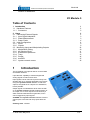
The I/O Module is an optional add-on to the iC5500
and iC6000 emulator.
It provides the capability to measure digital and
analog signals as well as drive them.
Input signals can be read out asynchronously from
winIDEA IDE or by external applications and scripts
using the isystem.connect interface. A real-time
capture, alongside the on-chip trace or standalone,
is also possible.
Output signals can likewise be driven from the IDE
or via isystem.connect. Beside simple assertion of
an output, one or more outputs can be driven by a
state machine based waveform generator, which
can be triggered by input signals.
testIDEA uses isystem.connect interface to assert
outputs prior to the test and verify inputs after the
test.
Ordering code: IC60011
iSYSTEM, May 2015
1/17
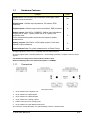
1.1
Hardware Features
Feature
IOM5
System Port: inter-emulator synchronization and trigger output,
100ohm series termination
Yes
Digital inputs: 10kOhm input impedance, 5V tolerant, ESD
protected
8
Digital outputs: 100ohm output series termination, ESD protected
8
Analog inputs: 8-bit ADCs, 6.25MSPS, 1MOhm input impedance,
range is ±5.0V with 1:1 probe, ±50V with a 10:1 probe, 3ns
acquisition time.
Power measurement probe uses these two inputs for power
measurement.
2
Analog outputs: 8-bit DACs, ±4.5V bipolar output, ±7mA drive,
100ohm output resistance
2
Current Sense Port: For power measurement via Power Probe
Yes
All digital signals are 3.3V LVTTL compatible and are ESD protected.
All analog signals have a Schottky diode over- / undervoltage protection, except the Current Sense
signals.
The maximum voltage on the Current Sense probe is 60V.
Nominal sampling rate of all inputs and outputs is 12.5MSps.
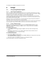
1.1.1
Connectors
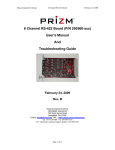
Connector Pinout
10-pin header for the System Port.
16-pin header for 8 digital inputs.
16-pin header for 8 digital outputs.
10-pin header for 2 analog outputs.
2 BNC connectors for 2 analog inputs.
10-pin header for Power Measurement Port
All connectors, except the BNCs, are standard Berg 2.54mm / 100mils raster.
iSYSTEM, May 2015
2/17
For analog inputs, standard scope probes can be used.
2
Usage
2.1
Connecting External Signals
2.1.1
Input Signal Adaptation
When connecting to external signals please make sure not to exceed the specified input and output
range of the IOM signal interface. If the digital input source voltage is higher than 5V, please condition
the signal source with a suitable resistor divider, or a resistor-Zener diode limiter.
In case, for example, a 24V source is connected directly to a module digital input, an excess input
current of about 18mA will flow through an input 1K resistor and a diode in the ESD protection device
to the module internal 5V power supply.
Although this may not sound catastrophic, it must be avoided. Any long-term exposure will lead to a
degradation of the module electronics due to electromigration.
On the other hand, if an analog input signal amplitude is smaller than the module input analog range, it
is recommended to add a suitable amplifier to make use of the full A/D converter resolution.
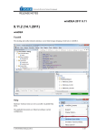
2.1.2
Power Measurement
When the IOM is switched to Power Measurement mode (Hardware/Options/ IO dialog, Use
AIN0/AIN1 for Power Measurement), the AIN0 is used for voltage measurement and AIN1 for
current measurement.
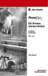
For voltage measurement
Connect AIN0 input to the target voltage at the RS-. That’s the low side of the target shunt
resistor.
If the voltage is higher than 5V, use a suitable resistor divider. Enter the divider ratio as a
Voltage/Multiply factor in the configuration dialog.
For current measurement
Disconnect the AIN1 from other sources
Use the Current Sense connector to connect the RS+ and RS- pins to a high side and a low side
of the target shunt resistor, respectively.
Specify the resistance of the RS shunt resistor in the configuration dialog.
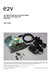
This schematic depicts correct power measurement setup.
iSYSTEM, May 2015
3/17
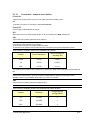
Note: The full-scale shunt voltage range is 250mV. So, for example, a 1Ω shunt resistor gives a
current range of 250mA.
Full-scale Shunt
Voltage
Shunt Resistance
Full-scale Current
Range
Shunt Power
Dissipation
250mV
1.00 Ω
0.25A
0.063W
250mV
0.25 Ω
1.00A
0.250W
250mV
0.10 Ω
2.50A
0.625W
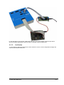
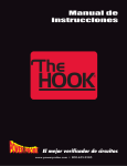
2.1.3
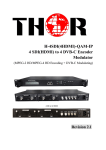
Power Probe
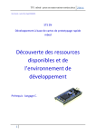
The PowerProbe is an optional power interface board. It is to be connected between a target power
supply and a target board itself. Additional connections are to be made for the IOM current and voltage
probes.
iSYSTEM, May 2015
4/17
2.1.3.1
Connectors, Jumpers and a Switch
P1 and P2
Target power supply inputs. Use one or the other. Maximum voltage is 20V.
P3
10-pin Berg connector to connect the IOM Current Probe.
P4 and P5
Power supply output towards the target.
ST1
BNC connector for the IOM Voltage Probe. To be connected to the AIN0 analog input.
JB1
Jumper block for selecting different shunt resistors.
Note:
1) Excessive current will burn the resistors.
2) Never set more than one jumper position at a time.
3) Selected shunt resistors must handle the heat generated by the power dissipated on them.
Three of the five available positions are populated with resistors:
Position
Shunt Resistance
Shunt Resistance
including JB1
0.25A
1.00 Ω
1.00 Ω
1A
0.25 Ω
0.26 Ω
2A5
0.10 Ω
0.11 Ω
The remaining two positions are available for a custom user setup with unpopulated resistors R5 and
R6.
Note that with lower shunt resistor values also the JB1 jumper resistance starts to play a role and may
influence the measurement. This can be easily compensated by slightly increasing the shunt
resistance value in the winIDEA setup dialog, by 0.01Ω, for example.
JB2
Jumper block for selecting different voltage ranges.
Note: 1) Never set more than one jumper position at a time.
Three of the five available positions are populated with resistor dividers:
Position
Resistors
Voltage Multiply
(configuration)
5V
0/10kΩ
1
10V
10/10kΩ
2
20V
30/10kΩ
4
iSYSTEM, May 2015
5/17
The remaining two positions are available for a custom user setup with unpopulated resistors R12 and
R13. The lower part of the voltage divider is set by the R9 of 10kΩ.
SW1
Switches target power on or off.
LD1
Power LED. Note that the LED needs a very small current to light and may glow because of a parasitic
current flowing, for example, when the emulator switched on and the target is off.
2.1.3.2
Connection Procedure
Switch off target and emulator
Power down the target supply
Select 2.5A or higher target current range to be on the safe side
Select 20V voltage range
Set SW1 to OFF position
Connect target supply to P1 or P2
Connect target to P4 or P5
Connect the ST1 voltage probe to the IOM AIN0 input
Connect P3 to the IOM Current Sense connector
Switch emulator on
Switch target supply on
Switch SW1 to ON position
Now, you are set to go.
iSYSTEM, May 2015
6/17
In case the target current and/or voltage are below the other given ranges, repeat the procedure
above and select appropriate ranges to improve resolution of the measurement.
2.1.3.3
Verification
To verify that the displayed voltage and current values are correct, use an independent voltage and
current measurement instrument.
iSYSTEM, May 2015
7/17
2.2
Initial Configuration
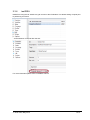
I/O module startup configuration is performed in Hardware/Options dialog.
All signals are accessible (HIL interface) by a configurable symbolic name. I/Os are mapped as
follows:
I/O
HIL Mapping
Example
Digital IN
DigitalIn.<name>
DigitalIn.DIN0
iSYSTEM, May 2015
8/17
Digital OUT
DigitalOut.<name>
DigitalOut.MyOutput
Analog IN
AnalogIn.<name>
AnalogIn.Temperature
Analog OUT
AnalogOut.<name>
AnalogOut.AOUT1
2.2.1
Inputs
Show
If set, the selected input will be shown in the HIL plugin.
2.2.1.1
Analog IN
Multiply
Multiplier specifies by how much the detected input is multiplied.
If a signal is externally divided by 10, set the multiplier to 10.
Advanced configuration
The
button next to signal name allows further configuration of an analog signal.
Range setting provides means to display an analog signal scaled to the range of interest.
Full
the signal is scaled between minimum and maximum
measurable range
Fixed the signal is scaled between the configured Min and
Max values
Auto
the signal is scaled between minimum and maximum
recorded values
2.2.2
Outputs
Driver
Driver
Effect
Disabled
The output cannot be driven
Manual
The output can be driven manually
Initial state
When the I/O module is initialized, the outputs will assume the specified initial state.
Control pin
Control output pin is a separate digital output pin which may be used for hardware control. It may be
used same as the digital output pins, but it cannot be traced.
iSYSTEM, May 2015
9/17
2.3
Monitoring Inputs and Manipulating Outputs
2.3.1
Manipulation Dialog
The Hardware/Tools/IO Module dialog provides the monitoring and manipulation capability of the I/O
Module.
2.3.1.1
Inputs
For all inputs the currently detected state is displayed and periodically refreshed.
iSYSTEM, May 2015
10/17
2.3.1.2
Outputs
Digital and Analog outputs which can be manually driven, can be asserted to the specified value.
Note: the value is asserted when the Set button is clicked.
Control pin
Control output pin is a separate digital output pin which may be used for hardware control.
2.3.2
HIL Monitor Plugin
Plugin/HIL Monitor provides the monitoring and manipulation capability of the I/O Module.
To modify an output, double click its value in the Value column.
To refresh the inputs manually, click the
icon.
To refresh the inputs manually, click the
icon.
iSYSTEM, May 2015
11/17
2.3.3
Evaluation Expressions
HIL variables can be used in standard expressions, by using the apostrophe ` prefix.
2.3.4
Trace
All Input signals are sampled simultaneously. The sampling
is configured in the Hardware/Options dialog.
Qualifier
Qualifier defines an additional filter for sampling.
Every clock – a sample is taken at every 20MHz internal
clock
Every 4 / 16 / 64 clocks – a sample is taken at a divided rate
On change – a sample is taken only when the states on the input lines change. This reduces the
amount of recorded data.
Note: only input lines which are not disabled in the Hardware/Options dialog are monitored for
change.
Show Outputs in Analyzer
If this option is checked, the outputs will be shown in the Analyzer Timeline.
2.3.4.1
Trigger configuration
The I/O module can generate a trigger for the iC5500 / iC6000 trace engine. Configuration is available
in the Manual trigger configuration dialog of the Analyzer window.
iSYSTEM, May 2015
12/17
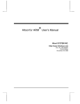
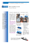
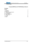
2.3.4.1.1 Trigger
Trigger determines the condition upon which the I/O module will signal the iC5000 to start recording.
Enabled
Enables the I/O module trigger output to the iC5000 trace engine.
Digital IN
Digital inputs 0 – 7 can be a trigger source. Two combinations of digital inputs (Condition 1 and
Condition 2) can be defined.
trigger if this input is in low state
trigger if this input is in high state
do not consider this input in the trigger condition
A condition is fulfilled if the enabled inputs match the configured value.
The trigger will be generated if either of enabled Conditions matches.
In the above example, trigger is generated if DIN4 is high and DIN6 is low, or AIN0 is below 2.9V.
Analog IN 0 and 1
Both analog inputs can be a trigger source. The trigger is generated if the measured voltage is Lower
or Higher than the specified threshold.
2.3.4.1.2 Qualifier
Qualifier determines the type of I/O module acquired information which is recorded in the trace buffer
and streamed to the host.
Record all
If this option is checked then all I/O module inputs are recorded. Otherwise no I/O samples are
recorded.
iSYSTEM, May 2015
13/17
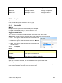
2.3.5
Profiler
Real-time profiling of I/O module’s signals is available in Analyzer’s Profiler mode.
To enable profiling, enable the AUX option in the Profiler configuration dialog.
Both inputs and outputs are traced and displayed in the timeline view.
Digital lines are treated as state variables, Analog lines as regular variables.
For more information refer to the Analyzer document.
iSYSTEM, May 2015
14/17
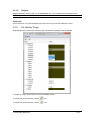
2.3.6
testIDEA
testIDEA is using the HIL interface to gain access to the I/O Module. This allows setting of inputs prior
to performing a unit test:
…and evaluation of outputs after the test:
For more information please refer to testIDEA manual.
iSYSTEM, May 2015
15/17
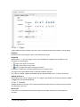
2.3.7
isystem.connect access
External applications can use isystem.connect to monitor and manipulate the I/O module via the HIL
interface class CHILController.
This Python example demonstrate s reading and writing analog and digital I/Os.
import isystem.connect as ic
#create connection and hil controller object
cMgr = ic.ConnectionMgr()
cMgr.connectMRU('')
hilCtrl = ic.CHILController(cMgr)
#set analog output to specified voltage level
def AnalogOutputWrite(channelName, voltageLevel):
hilCtrl.write('AnalogOut.' + channelName + ': ' + voltageLevel)
#get analog input voltage level
def AnalogInputRead(channelName):
return hilCtrl.read('AnalogIn.' + channelName)
#set digital output to specified level
def DigitalOutputWrite(channelName, state):
hilCtrl.write('DigitalOut.' + channelName + ': ' + state)
#get digital input state
def DigitalInputRead(channelName):
return hilCtrl.read('DigitalIn.' + channelName)
AnalogOutputWrite('AOUT0', '1.8')
print "Analog input AIN0 voltage level: ", AnalogInputRead('AIN0')
DigitalOutputWrite('DOUT0', 'HIGH')
print "Digital input DIN0 state: ", DigitalInputRead('DIN0')
iSYSTEM, May 2015
16/17
Disclaimer: iSYSTEM assumes no responsibility for any errors which may appear in this document, reserves the
right to change devices or specifications detailed herein at any time without notice, and does not make any
commitment to update the information herein.
iSYSTEM . All rights reserved.
iSYSTEM, May 2015
17/17