1
Report
First Version
- G Bernat - V Caselles - JL Lisani
Integrated module for analysis / synthesis
/ matching - First version
CHARM D12 deliverable
Report - Universitat de les Illes Balears
Contents
1. Introduction
2. Validation and registration in the context of CHARM
3.The integrated environment for 3D reconstruction and validation
3.1. Introduction
3.2. General description of the interface
3.3 File formats of the reconstruction module
3.4 File formats of the validation module
3.5 Data structure
3.6 Visualisation controllers
3.6.1 Video controllers
3.6.2 Zoom controllers
4. User manual
4.1 Reconstruction module
4.1.1 Loading files
4.1.2 Camera calibration
4.1.3 Reconstruction
4.2. Registration/validation module
4.2.1. Loading an arm
4.2.2. Trajectory loading
4.2.3. Centre of masses and principal directions loading
4.2.4. Saving reconstructions
4.2.5. Play synchronising
4.2.6. Video controllers
4.2.7. Quitting
4.3 Error messages
5. Spatial registration and validation results
December 1996
2
Report
First Version
- G Bernat - V Caselles - JL Lisani
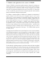
1. Introduction
Deliverable D12, Integrated module for analysis / synthesis / matching,
constitutes the module for the CHARM project validation, aiming at analysing the
correspondence of images coming from real sources (medical origin, video sequences) with
synthetically generated ones using CHARM methods and thus assessing somehow the
results of the project as a whole. Partial inspiration for this deliverable comes from the work
performed for the second year deliverable D8, An interface for matching, where some
of the validation problems were approached in a prototype way.
Due to the current limitations of the CHARM results, in particular the unfeasibility of
simulating the behaviour of a sufficient number of muscles and other tissues through finite
element methods, the final validation has been performed by comparing trajectories of 3D
bones corresponding to a real movement, and reconstructed from fluoroscopies taken from
different perspectives, with simulated trajectories of some bones using the 3D models
obtained from the Visual Human Dataset and with movements driven by the control methods
developed by CHARM.
In this report we describe:
- the environment for 3D reconstruction of objects from the real sources used for
CHARM validation namely image sequences obtained through video cameras
and fluoroscopies, using stereoscopy;
- the validation environment where these images are compared with the simulated
ones, specifically the tools for comparing the trajectories of the real and
simulated cases, and the registration problems analysed;
- and finally we discuss the validation results and perspectives.
In an appendix we discuss some more advanced methods for moving images analysis which
have not been yet integrated in the module, due to time constraints in the project, which
limited the extension to which more advanced methods could be tested and integrated.
We recall that this deliverable is complementary of the deliverable replacing D11, Test
sequences for validation, where the setting of the experiences for the obtention of the
sequences, the methods used for camera calibration and 3D reconstruction, both of video and
fluoroscopy sequences, and the results obtained are discussed
But first we discuss the validation questions as perceived in the context of the CHARM
project and, specifically, in this deliverable.
December 1996
3
Report
First Version
- G Bernat - V Caselles - JL Lisani
2. Validation and registration in the context of CHARM
The aim of CHARM is to obtain better synthetic animation of humans by developing new
methods; different modalities of moving 3D images are analyzed and/or synthesized and have
to be compared in order to validate these methods. The type of images for use in CHARM
range from 3D reconstructions obtained from real sources, such as MR, CAT, fluoroscopies
or video, to synthetically generated movements coming from physically based simulations,
namely, on biomechanics and high-level motion control.
The validation / registration problem of CHARM can be compared to the introduction of
graphics techniques in the medical context, where tomographic images are used in concert
with each other, so that the correlation of 3D tomographic diagnostic images obtained from
different modalities such as PET or MR, or from the same modality in different times has
become clinically significant in recent years. It was natural for the CHARM partnership to
take this graphics approach and enhance it, exploiting current hardware and software
developments for the use of multi-modal moving 3D images. In the clinical approach the
questions are image matching and the associated registration problems - registration means
determining the geometric relationship between multi-modal image data sets in order to
perform the best possible superposition of the images -. The CHARM validation questions
are slightly different.
Comparing images from different sources and checking for the accuracy and correspondence
of the different representations is one of the approaches for testing whether our models
represent an effective progress in synthesizing human animation. This problem is somehow
different from the medical image matching where in the clinical context the aim of matching
can be, for instance, registering scans of the same patient with each other and with CT scans
or relate them to a standard atlas in order to perform the best possible superposition of the
images. In our context we are interested in getting the appropriate reference frames (both
spatial and temporal) which allow the study of coincidences and discrepancies among multimodal images, because it is in the accuracy of the methods of synthetic generation of
deformation and movement what we are interested in assessing.
We take mainly this visualisation approach, which allows clinicians and other non-technical
users to assess the validity of the results of the project by visual comparison of different
modalities of moving 3D images, and we also aim at providing some more analytical tools to
test also the results. This approach gets its strength both from graphics and the current
medical approaches, while the objectives are different from the clinical approach, namely, the
best matching is not the optimum, but the most accurate comparison with a suitable
referencing.
December 1996
4
Report
3. The integrated
validation
First Version
environment
for
- G Bernat - V Caselles - JL Lisani
3D
reconstruction
and
3.1. Introduction
The environment developed by UIB for the CHARM project integrates the tasks of 3D
reconstruction of moving objects from "real" image sequences, and the validation of the
results by comparing (mainly perceptually at the current stage, but helped by some
automatised tools) multi-modal image sequences, after the temporal synchronisation and
spatial registration of the different sources. The resulting environment is composed of two
modules, the first one is the reconstruction module, for 3D reconstruction of objects from
frames of the same object from different perspectives, with the capability of generating
sequences of reconstructed bones in Inventor format, together with a file containing
essentially the trajectories of the movement. After performing calibration of the cameras, by
operator identification of corresponding points for the different camera images (helped by
epipolar lines), a sequence of reconstructed objects is generated in Inventor format. The
second module is the validation module, which shares the common aspects of the interface
with the former but which is separated from it for optimising memory and loading
management. The trajectory file from the reconstruction module is used to generate the
animation sequence of the shoulder-arm in a window, which will be compared with another
movement which is loaded in another window, this time synthetically generated with
CHARM methods, for the validation. The validation module can load independent bones
reconstructions, provided the reconstructions are in the CHARM developed format based on
Inventor. Some automatised help tools are also shown. As indicated earlier, the final
validation takes place only on some bones movement, both reconstructed from
fluoroscopies, and simulated on the VHD-based data.
3.2. General description of the interface
The interface for the environment, especially the calibration/reconstruction module, has been
chosen to appear very similar to the interface for matching developed as CHARM D8,
although the functionalities and underlying structures are widely different.
The reasons for keeping a seemingly looking environment are twofold. On one hand, the
tiled window system for D8 was seen as very convenient for novice users and we favored
keeping the similarities, which gives an advantage to the user, helping in its familiarisation
with the tasks although they are different.
On the other hand, as the main functionality of this module is getting a reconstructed 3D
object from different views, it seemed convenient to follow the quite standard interface used
for 3D modelling in coomercial packages for image synthesis and animation, where the users
December 1996
5
Report
First Version
- G Bernat - V Caselles - JL Lisani
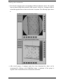
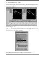
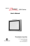
have 4 windows showing different planes and a view of the 3D object. In in our case, the
user has some windows showing different perspectives (albeit real) of the same object and
then the 3D reconstruction. This approach gets very positively striking results when using
fluoroscopies, where the images shown are images taken at orthogonal perspective planes,
which is the standard for modelling packages. Although the module has four subwindows,
three for the perspective images and one (the upper-right one) for the reconstructed object, it
is currently able to handle up to five different perspectives.
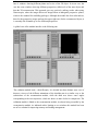
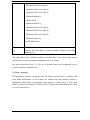
A global view of the module interface is the following one:
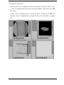
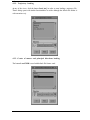
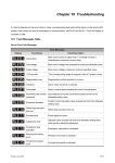
The validation module looks a bit differently. It is divided into three distinct areas, two of
them are viewers of the different animations of the shoulder-arm in a similar way as the
subwindows of the reconstruction module, while the third area shows some angles
corresponding to the two trajectories, which are shown as nine clocks for comparison. The
validation module is linked to the reconstruction module, its objects being accessible by the
reconstruction module. As indicated earlier, limiting to two windows this module has been
an ad hoc solution for improving memory and loading management.
December 1996
6
Report
First Version
- G Bernat - V Caselles - JL Lisani
The following picture gives an indication of the validation module interface:
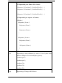
3.3 File formats of the reconstruction module
The input formats for the reconstrucion modules are, classified according to extensions, the
following ones:
*.iv
File in Inventor format. The format has to be appropriate for the internal
structures of the module, otherwise it will be rejected. There are three
types of suitable formats:
1) Representing vertices and faces of a bone:
SoSeparator {
SoCoordinate3{
point[...
}
SoIndexedFaceSet{
coorIndex[...
}
...
}
December 1996
7
Report
First Version
- G Bernat - V Caselles - JL Lisani
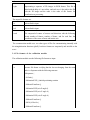
2) Representing one frame with n bones:
SoSeparator {SoCoordinate3{} SoIndexedFaceSet{} ... }
SoSeparator {SoCoordinate3{} SoIndexedFaceSet{} ... }
...
SoSeparator {SoCoordinate3{} SoIndexedFaceSet{} ... }
3) Representing a sequence of frames:
SoBlinker {
SoSeparator {#Frame 1
SoSeparator {#bone 1}
...
SoSeparator {#bone n}
}
...
SoSeparator {#Frame n
SoSeparator {#bone 1}
...
SoSeparator {#bone n}
}
}
*.cal
Representing a camera calibration, by means of a list of points whose
number is multiple of five and each tuple is given by:
coordinate pixel x
coordinate pixel y
coordinate 3D x
coordinate 3D y
coordinate 3D z
*.rgb
December 1996
Representing a 2D image in RGB format
8
Report
*.rgbs
First Version
- G Bernat - V Caselles - JL Lisani
Representing a sequence of 2D images in RGB format. This file is
edited with the help of a text editor, and each row is the path to the file
with the 2D image and the order is the order of the frames for
visualisation or processing.
The output file formats are:
*.iv
as described in input
*.cal
as described in input
*.cmd
File composed of centres of masses and directions with the following
format: number of frames, number of bones, and for each line, the
coordinates of the centre of mass and inertia axes.
The reconstruction module uses two other types of files for communicating internally with
the triangularisation functions (qhull), but these formats are temporarily and invisible to the
users.
3.4 File formats of the validation module
The validation module uses the following file formats as input:
*.iv
Inventor file format verifying that the last son hanging from the main
node is a Separator with the following structure:
SoSeparator {
SoUnits{}
SoRatationXYZ{} #initial positioning rotation
SoMatrixTransform{}
SoRatationXYZ{axis Z angle 0}
SoRatationXYZ{axis Y angle 0}
SoRatationXYZ{axis X angle 0}
SoMatrixTransform{}
SoFile{#Clavicle}
SoMatrixTransform{}
December 1996
9
Report
First Version
- G Bernat - V Caselles - JL Lisani
SoRatationXYZ{axis Z angle 0}
SoRatationXYZ{axis Y angle 0}
SoRatationXYZ{axis X angle 0}
SoMatrixTransform{}
SoFile{#Ulna}
SoMatrixTransform{}
SoRatationXYZ{axis Z angle 0}
SoRatationXYZ{axis Y angle 0}
SoRatationXYZ{axis X angle 0}
SoMatrixTransform{}
SoFile{#Humerus}
}
*.trj
Trajectory file with number of frames, number of degrees of freedom
and trajectories
The output files for the validation module are inventor files of any of the input formats
specified above for the reconstruction module for a bone or a frame.
One must remark that all the *.iv files are in Inventor format and consequently can be
visualised with the command ivview.
3.5 Data structure
The internal data structure corresponds to the file format described above, eventually with
some added sofistications. As an example, the internal bone data structure includes a
SoSeparator which allows to encapsulate deeper structure, in other terms, it is the node
father of a subtree; SoCoordinate3 which is a set of 3D points and SoIndexedFaceSet, which
is a set of indexed fases.
December 1996
10
Report
First Version
- G Bernat - V Caselles - JL Lisani
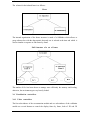
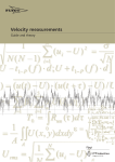
The scheme for the isolated bone is as follows:
Bone
The internal organisation of the bones structure is made of a SoBlinker which allows to
group subtrees but with the characteristic that only one is selected at the time and which is
used to simulate a sequence or film frame by frame.
Full Structure of a set of bones
The number of five has been chosen to manage more efficiently the memory and loading,
otherwise, the environment gets very heavily loaded.
3.6 Visualisation controllers
3.6.1 Video controllers
The four subwindows of the reconstruction module and two subwindows of the validation
module use several buttons to control the display frame by frame, both of 2D and 3D
December 1996
11
Report
First Version
- G Bernat - V Caselles - JL Lisani
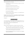
sequences. The functionalities are inspired by the standard commercial video players as were
designed in the deliverable D8. The meaning is:
• All Backwards or rewind: defines the first frame in the sequence as the current
(and visualized) one.
• All Forward: sets the last frame as the current frame.
• Step Backwards: sets the previous frame as the current frame.
• Step Forward: the folowing frame becomes the current one.
• Play: a non-stop cycling display of the full sequence.
• Stop: Interrupt the cycling display.
• Selection: sets directly wich frame as current one. It is only enabled when the
number of frames is bigger than one.
Currently, the speed for Play visualisation is set to one frame per second and it is not user
modifiable. The video controllers are not enabled when only one image or reconstructed
frame is loaded in the corresponding subwindow.
They appear as:
The video functionalities in the video controller for the validation module include the same as
in the reconstruction module, with the added option for synchronising the views in the
different subwindows. This option is activated through a button.
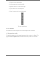
3.6.2 Zoom controllers
The three reconstruction subwindows have several buttons for image control, as follows
• Home: to take a point of view such that the whole object can be seen in the
window; this function is automatically performed any time a new file is loaded.
• Point=Pixel: In order to get that a pixel image has the dimension of a pixel screen.
This is the minimum zooming suggested for reconstruction tasks.
• Zoom: This is another facility essential for the reconstruction tasks. Magnifying
helps the precision of the task.
December 1996
12
Report
First Version
- G Bernat - V Caselles - JL Lisani
• Unzoom: reverses zoom operation.
• Left: the camera view is moved to the left.
• Right: the camera view is moved to the right.
• Up: the camera view is moved upwards.
• Down: the camera view is moved downwards.
The zoom control buttons
4. User manual
The modules have been developed to run on a Silicon Graphics Unix environment.
4.1 Reconstruction module
To launch the program use the command recons and the execution is validated. The
programs recons and qhull should be inside the same directory for the correct execution.
December 1996
13
Report
First Version
- G Bernat - V Caselles - JL Lisani
A four window environment appears:
December 1996
14
Report
First Version
- G Bernat - V Caselles - JL Lisani
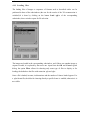
4.1.1 Loading files
The loading files of images or sequences of formats such as described earlier can be
performed in three of the subwindows (the one for the results of the 3D reconstruction is
excluded).It is done by clicking on the button Load rgb/s of the corresponding
subwindow; then a window opens for file selection.
The images are loaded in the corresponding subwindow, and if there was another image or
sequence loaded, it is replaced by the newer one. Apart from the OK and Cancel typical
dialog, the option Filter allows for choosing only some type of files to display as for
loading; the default are the files with extension .rgb and .rgbs.
Once a file is loaded, its name, its dimensions and the number of frames loaded appear. For
a .rgbs format file, the slider for choosing directly a specific frame is enabled; otherwise it is
not visible.
December 1996
15
Report
First Version
- G Bernat - V Caselles - JL Lisani
Again, the object appears initally set to the subwindow size as indicated in the following
picture:
The video controller with the direct to frame option enabled appears as:
4.1.2 Camera calibration
Camera calibration (obtaining the parameters corresponding to a viewpoint) can be done in
two ways: manually (to obtain the first calibration) or loading it from a file (after the
calibration has been performed and then it is loaded when required, or for simulations).
December 1996
16
Report
First Version
- G Bernat - V Caselles - JL Lisani
In order to load a calibration the user clicks on the button Load Cal in the corresponding
subwindow and a window for choosing the calibration and loading it appears as follows:
In order to perform a manual calibration the user has to perform the following steps:
• Click on the button Start Calib at the corresponding subwindow. The button changes to
End Calib.
• Then select a point in the image; a window appears with the screen coordinates
corresponding to this point requesting to introduce the 3D coordinates and to validate
them.
December 1996
17
Report
First Version
- G Bernat - V Caselles - JL Lisani
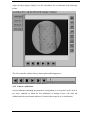
• Once the calibrated point is calibrated, it appears in red to avoid re-using it. Calibration
requires a minimum of 6 points and an upper limit of 20 points has been set. The
following picture shows that feature:
• Once chosen all the calibration points required, the user executes the calibration by
clicking on the button End Calib which now turns to Start Calib.
• Finally it is recommended to save the calibration by clicking on the button Save Cal
which opens the appropriate selection window.
4.1.3 Reconstruction
In order to start the reconstruction, the points of view corresponding to the images of the
object to be reconstructed should have been calibrated previously, and a a minimum of two
points of view is necessary.
In order to start the reconstruction the user clicks the button Start Rec.
Two ways of reconstruction have been implemented, point by point and by sections. Both of
them can be used simultaneously for the same object reconstruction.
December 1996
18
Report
First Version
- G Bernat - V Caselles - JL Lisani
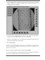
Point by point reconstruction:
• We select the conjugate points corresponding to different calibrated cameras. The epipolar
lines are drawn to help in this selection. When a point is clicked at a viewpoint it turns to
red and the epipolar lines are drawn at the other viewpoints. The following figure shows
it:
• After several groups of conjugate points have been determined the object can be
reconstructed by clicking on the Valid Rec button. A minimum of four groups is
required for the visualisation in the reconstruction subwindow
December 1996
19
Report
First Version
- G Bernat - V Caselles - JL Lisani
Section based reconstruction:
• Only two points of view (orthogonal) in the left subwindows can be used. Then we select
a couple of conjugate points and click on the button Section, which turns to an End
Sec button.
• Another couple of conjugate points is selected and then by clicking on the End S e c
button the section is computed and is represented in the up left subwindow, as appears
next:
December 1996
20
Report
First Version
- G Bernat - V Caselles - JL Lisani
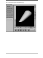
The reconstructed object appears in the following way:
December 1996
21
Report
First Version
- G Bernat - V Caselles - JL Lisani
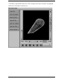
A wireframe representation allows for easier viewing of the centre of masses and principal
inertia axes of the object as shown next:
December 1996
22
Report
First Version
- G Bernat - V Caselles - JL Lisani
4.2. Registration/validation module
Type the command regist and then execution is started. The following image gives a view
of the module's interface:
4.2.1. Loading an arm
At any of the views, click the button Load Arm in order to start loading a model arm in the
file format described earlier. Then a dialog opens:
Similar functionalities as previously are available. The default extension is .iv.
December 1996
23
Report
First Version
- G Bernat - V Caselles - JL Lisani
4.2.2. Trajectory loading
At any of the views, click the button Load traj in order to start loading a trajectory file.
Then a dialog opens with similar functionalities as earlier although the default file format is
with extension .traj.
4.2.3. Centre of masses and principal directions loading
The button Load CMD is used with default file format .cmd.
December 1996
24
Report
First Version
- G Bernat - V Caselles - JL Lisani
4.2.4. Saving reconstructions
This functionality saves the current frame, which can be loaded into the reconstruction
module for computation of centres of masses and principal directions. It is activated by
clicking the button Save recs.
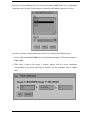
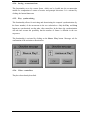
4.2.5. Play synchronising
This functionality allows for activating and desactivating the temporal synchronisation (by
the frame number) of the movements in the two subwindows. Only the Play and Stop
buttons are synchronised, not the other video controllers. In the future the synchronisation
will take into account the possibility that the number of frames is different in the two
sequences.
This functionality is activated by clicking on the Sincro Play button. Messages ask for
confirmation of the activation or deactivation:
4.2.6. Video controllers
They have been already described.
December 1996
25
Report
First Version
- G Bernat - V Caselles - JL Lisani
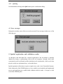
4.2.7. Quitting
For both modules clicking on the Quit button opens a confirmation dialog:
4.3 Error messages
During the execution, errors of the user can be corrected. Error message windows are of the
following type:
5. Spatial registration and validation results
As indicated in the deliverable D11, temporal registration of the movements is manually
obtained by having a synchronising event in the real sequences, through which static
reconstruction can be performed, and the simulation can be synchronised, which can be then
played visually in a synchronised way, as described above.
Spatial registration of the objects is quite a complex issue, with a lot of biomedical literature.
In the framework of the CHARM project we have studied several methods and implemented
an easy and significant one to enable initial validation with the modes of images we deal
with in this CHARM phase.
December 1996
26
Report
First Version
- G Bernat - V Caselles - JL Lisani
We have chosen to register the images based on two simple physical characteristics of the
bones: the centre of masses - giving the position - and the principal inertia axes - giving the
orientation -. They are computed from the reconstructed surface coming both from the bones
reconstructed from fluoroscopies and from the VHD based models.
As we want to compare trajectories, the inertia axes are the really significant characteristics
which allow us to compute the evolution of some angles which show the evolution of some
joints.
So far, we have not achieved a good automatic registration based on these parameters which
could be used for better visual registration and matching including skin surface. The
movements used for the validation are so different that the validation shows them as different
with very little problems.
December 1996
27
Report
First Version
- G Bernat - V Caselles - JL Lisani
APPENDIX 1: Validation through EMG
Another resource for validation which was preliminary explored by UIB, through the
Physiology Professor Ruben Rial, was to check the results obtained in the CHARM project
through optimisation techniques about the activation levels of the actuators against actual
measurements. Two techniques are available in practice to estimate the activation level of a
muscle actuator: the electromyographic measurements (EMG) and the intramuscular pressure
measurements (IMP). Both methods provide complementary informations on the muscle
activation state. However, as they provide more accurate data than IMP measurements, EMG
measurements have been more commonly used.
Preliminary work was developed: bibliographical survey was conducted, experiences were
designed to get EMG recordings, and first trials performed. Surface EMGs were recorded in
these first trials using conventional adhesive surface electrodes (paper and magnetic FM tape
were used), while the subject performed movements of abduction and adduction of about
30°, with and without loading (in this case, against a 10 kg load applied to the elbow); six
simultaneous channels were used for the main muscles.
December 1996
28
Report
First Version
- G Bernat - V Caselles - JL Lisani
APPENDIX 2: Some moving images tools
Although the more advanced image analysis tools are not fully integrated in the validation
environment, due to the late integration of this part, the methods for allowing the tracking of
the objects and computing the kinematics parameters have been developed. We enclose two
reports: Segmentation of 3D images and video sequences (V Caselles and J L Lisani) and
Snakes in movement (V Caselles and B Coll).
December 1996
29