1
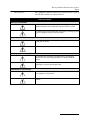
Density Gradient Fractionation Systems Installation and Operation Guide #69-3873-246 Copyright © 2009, Teledyne Isco, Inc. Revision A, February 18, 2010. Foreword This instruction manual is designed to help you gain a thorough understanding of the operation of the equipment. Teledyne Isco recommends that you read this manual completely before placing the equipment in service. Although Teledyne Isco designs reliability into all equipment, there is always the possibility of a malfunction. This manual may help in diagnosing and repairing the malfunction. If the problem persists, call or e-mail the Teledyne Isco Technical Service Department for assistance. Simple difficulties can often be diagnosed over the phone. If it is necessary to return the equipment to the factory for service, please follow the shipping instructions provided by the Customer Service Department, including the use of the Return Authorization Number specified. Be sure to include a note describing the malfunction. This will aid in the prompt repair and return of the equipment. Teledyne Isco welcomes suggestions that would improve the information presented in this manual or enhance the operation of the equipment itself. Teledyne Isco is continually improving its products and reserves the right to change product specifications, replacement parts, schematics, and instructions without notice. Contact Information Customer Service Phone: (800) 228-4373 (USA, Canada, Mexico) (402) 464-0231 (Outside North America) Fax: (402) 465-3022 Email: [email protected] Technical Support Phone: Email: (800) 775-2965 (Analytical) (866) 298-6174 (Samplers and Flow Meters) [email protected] Return equipment to: 4700 Superior Street, Lincoln, NE 68504-1398 Other Correspondence Mail to: P.O. Box 82531, Lincoln, NE 68501-2531 Email: [email protected] Web site: www.isco.com Revised March 17, 2009 Density Gradient Fractionation Systems Safety Density Gradient Fractionation Systems Safety General Warnings Before installing, operating, or maintaining this equipment, it is imperative that all hazards and preventive measures are fully understood. While specific hazards may vary according to location and application, take heed of the following general warnings: WARNING Liquids associated with this instrument may be classified as carcinogenic, biohazard, flammable, or radioactive. Should these liquids be used, it is highly recommended that this application be accomplished in an isolated environment designed for these types of materials in accordance with federal, state, and local regulatory laws, and in compliance with your company’s chemical/hygiene plan in the event of a spill. AVERTISSEMENT Eviter de répandre des liquides dangereux. Les liquides qui sont analysés dans cet instrument peuvent être cancérigènes, hasards biologiques, inflammables, ou radioactifs. Si vous devez utiliser tels liquides, il est très recommandé que vous le faites à l'intérieur d'un environnement isolé conçu pour tels liquides. Cet environnement isolé devrait être construit selon les règlements fédéraux, provinciaux, et locaux, aussi que le plan de votre compagnie qui concerne l'évènement d'un accident avec les matières hasardeuses. WARNING Avoid hazardous practices! If you use this instrument in any way not specified in this manual, the protection provided by the instrument may be impaired. AVERTISSEMENT Éviter les usages périlleux! Si vous utilisez cet instrument d’une manière autre que celles qui sont specifiées dans ce manuel, la protection fournie de l’instrument peut être affaiblie; cela augmentera votre risque de blessure. iii Density Gradient Fractionation Systems Safety WARNING If this system uses flammable organic solvents, Teledyne Isco recommends that you place this system in a well-ventilated environment, designed for these types of materials. This environment should be constructed in accordance with federal, state, and local regulations. It should also comply with your organization’s plan concerning chemical and hygiene mishaps. In all cases use good laboratory practices and standard safety procedures. AVERTISSEMENT Ce système peut utiliser des dissolvants organiques inflammables. Pour réduire le péril qui peut être causé par l'accumulation des vapeurs explosives, Teledyne Isco recommande que vous installez ce système dans un environnement bien-aéré qui est conçu pour les matières hasardeuses. Cet environnement devrait être construit selon les règlements fédéraux, provinciaux, et locaux. Aussi, il devrait se conformer au plan de votre organisation qui concerne les mésaventures de l'hygiène ou de chimique. En tout cas, utilisez toujours de pratiques bonnes de la laboratoire et des procédures standardes de la sûreté. Hazard Severity Levels This manual applies Hazard Severity Levels to the safety alerts, These three levels are described in the sample alerts below. CAUTION Cautions identify a potential hazard, which if not avoided, may result in minor or moderate injury. This category can also warn you of unsafe practices, or conditions that may cause property damage. WARNING Warnings identify a potentially hazardous condition, which if not avoided, could result in death or serious injury. DANGER DANGER – limited to the most extreme situations to identify an imminent hazard, which if not avoided, will result in death or serious injury. iv Density Gradient Fractionation Systems Safety Hazard Symbols The equipment and this manual use symbols used to warn of hazards. The symbols are explained below. Hazard Symbols Warnings and Cautions The exclamation point within the triangle is a warning sign alerting you of important instructions in the instrument’s technical reference manual. The lightning flash and arrowhead within the triangle is a warning sign alerting you of “dangerous voltage” inside the product. Symboles de sécurité Ce symbole signale l’existence d’instructions importantes relatives au produit dans ce manuel. Ce symbole signale la présence d’un danger d’électocution. Warnungen und Vorsichtshinweise Das Ausrufezeichen in Dreieck ist ein Warnzeichen, das Sie darauf aufmerksam macht, daß wichtige Anleitungen zu diesem Handbuch gehören. Der gepfeilte Blitz im Dreieck ist ein Warnzeichen, das Sei vor “gefährlichen Spannungen” im Inneren des Produkts warnt. Advertencias y Precauciones Esta señal le advierte sobre la importancia de las instrucciones del manual que acompañan a este producto. Esta señal alerta sobre la presencia de alto voltaje en el interior del producto. v Density Gradient Fractionation Systems Safety vi Density Gradient Fractionation Systems Table of Contents Section 1 Introduction 1.1 1.2 1.3 1.4 System Features . . . . . . . . . . . . . . . . . . . . . . . . . . . . . . . . . . . . . . . . . . . . . . . . . . . . Specifications. . . . . . . . . . . . . . . . . . . . . . . . . . . . . . . . . . . . . . . . . . . . . . . . . . . . . . . About this Manual. . . . . . . . . . . . . . . . . . . . . . . . . . . . . . . . . . . . . . . . . . . . . . . . . . . For Additional Information. . . . . . . . . . . . . . . . . . . . . . . . . . . . . . . . . . . . . . . . . . . . 1-1 1-4 1-4 1-4 Section 2 Installation 2.1 Unpacking . . . . . . . . . . . . . . . . . . . . . . . . . . . . . . . . . . . . . . . . . . . . . . . . . . . . . . . . . 2-1 2.2 System Assembly. . . . . . . . . . . . . . . . . . . . . . . . . . . . . . . . . . . . . . . . . . . . . . . . . . . . 2-1 2.2.1 UA-6 Detector and Optical Unit Preparation . . . . . . . . . . . . . . . . . . . . . . . 2-2 2.2.2 Foxy R1 Fraction Collector . . . . . . . . . . . . . . . . . . . . . . . . . . . . . . . . . . . . . . 2-2 2.2.3 Retriever 500 Fraction Collector . . . . . . . . . . . . . . . . . . . . . . . . . . . . . . . . . . 2-2 2.2.4 Tube Piercer Preparation . . . . . . . . . . . . . . . . . . . . . . . . . . . . . . . . . . . . . . . 2-2 2.3 Installation of System with Foxy R1 Fraction Collector . . . . . . . . . . . . . . . . . . . . . 2-4 2.4 Installation of System with Retriever 500 Fraction Collector . . . . . . . . . . . . . . . . 2-8 2.5 Changing the Flow Cell Aperture . . . . . . . . . . . . . . . . . . . . . . . . . . . . . . . . . . . . . 2-12 Section 3 Operation 3.1 System Preparation. . . . . . . . . . . . . . . . . . . . . . . . . . . . . . . . . . . . . . . . . . . . . . . . . . 3-1 3.1.1 Tris Pump . . . . . . . . . . . . . . . . . . . . . . . . . . . . . . . . . . . . . . . . . . . . . . . . . . . . 3-1 3.1.2 UA-6 Detector and Optical Unit . . . . . . . . . . . . . . . . . . . . . . . . . . . . . . . . . . 3-3 3.1.3 Foxy R1 Fraction Collector . . . . . . . . . . . . . . . . . . . . . . . . . . . . . . . . . . . . . . 3-3 3.1.4 Retriever 500 Fraction Collector . . . . . . . . . . . . . . . . . . . . . . . . . . . . . . . . . . 3-6 3.1.5 Tube Piercer . . . . . . . . . . . . . . . . . . . . . . . . . . . . . . . . . . . . . . . . . . . . . . . . . . 3-6 3.1.6 Chase Liquid . . . . . . . . . . . . . . . . . . . . . . . . . . . . . . . . . . . . . . . . . . . . . . . . . 3-9 3.2 Fractionation . . . . . . . . . . . . . . . . . . . . . . . . . . . . . . . . . . . . . . . . . . . . . . . . . . . . . . 3-10 3.3 Post Fractionation . . . . . . . . . . . . . . . . . . . . . . . . . . . . . . . . . . . . . . . . . . . . . . . . . . 3-13 3.4 Post Run Cleaning. . . . . . . . . . . . . . . . . . . . . . . . . . . . . . . . . . . . . . . . . . . . . . . . . . 3-13 Appendix A Tables A.1 Density Gradient Tables . . . . . . . . . . . . . . . . . . . . . . . . . . . . . . . . . . . . . . . . . . . . . A-1 vii Density Gradient Fractionation Systems Table of Contents List of Figures 1-1 Density Gradient Fractionation System (shown with Foxy R1 fraction collector) . . . . . . . . . . . . . . . . . . . . . . . . . . . . . . . . . 1-2 2-1 Attaching flow cell to tube piercer . . . . . . . . . . . . . . . . . . . . . . . . . . . . . . . . . . . . . . 2-3 2-2 System connections with a Foxy R1 fraction collector (rotated view) . . . . . . . . . . 2-5 2-3 System tubing connections with Foxy R1 fraction collector . . . . . . . . . . . . . . . . . 2-6 2-4 System connections with a Retriever 500 fraction collector (rotated view) . . . . . 2-9 2-5 System tubing connections with Retriever 500 fraction collector . . . . . . . . . . . . 2-10 2-6 Flow cell aperture installation . . . . . . . . . . . . . . . . . . . . . . . . . . . . . . . . . . . . . . . 2-12 3-1 Collect fractions by volume counts . . . . . . . . . . . . . . . . . . . . . . . . . . . . . . . . . . . . . 3-4 3-2 Cut peaks by peak widths and collect all fluids . . . . . . . . . . . . . . . . . . . . . . . . . . . 3-5 3-3 Basic method settings . . . . . . . . . . . . . . . . . . . . . . . . . . . . . . . . . . . . . . . . . . . . . . . 3-5 3-4 Piercing mechanism . . . . . . . . . . . . . . . . . . . . . . . . . . . . . . . . . . . . . . . . . . . . . . . . . 3-7 3-5 Styrene-butadiene rubber septum and collar set . . . . . . . . . . . . . . . . . . . . . . . . . . . . . . . . . . . . . . . . . . . . . . . . 3-7 3-6 Install the collar and ring . . . . . . . . . . . . . . . . . . . . . . . . . . . . . . . . . . . . . . . . . . . . 3-8 3-7 Inserting the centrifuge tube . . . . . . . . . . . . . . . . . . . . . . . . . . . . . . . . . . . . . . . . . 3-10 3-8 Piercing the centrifuge tube . . . . . . . . . . . . . . . . . . . . . . . . . . . . . . . . . . . . . . . . . 3-11 List of Tables 1-1 1-2 2-1 2-2 2-3 2-4 2-5 3-1 3-2 A-1 A-2 A-3 A-4 System Features . . . . . . . . . . . . . . . . . . . . . . . . . . . . . . . . . . . . . . . . . . . . . . . . . . . . 1-3 System Specifications . . . . . . . . . . . . . . . . . . . . . . . . . . . . . . . . . . . . . . . . . . . . . . . . 1-4 Tubing and Lengths . . . . . . . . . . . . . . . . . . . . . . . . . . . . . . . . . . . . . . . . . . . . . . . . . 2-7 Connection Hardware . . . . . . . . . . . . . . . . . . . . . . . . . . . . . . . . . . . . . . . . . . . . . . . 2-7 Tubing and Lengths . . . . . . . . . . . . . . . . . . . . . . . . . . . . . . . . . . . . . . . . . . . . . . . . 2-11 Connection Hardware . . . . . . . . . . . . . . . . . . . . . . . . . . . . . . . . . . . . . . . . . . . . . . 2-11 Flow Cell Illuminated Volumes . . . . . . . . . . . . . . . . . . . . . . . . . . . . . . . . . . . . . . . 2-12 Recommended Flow Rates . . . . . . . . . . . . . . . . . . . . . . . . . . . . . . . . . . . . . . . . . . . . 3-2 Collar and Ring Selection . . . . . . . . . . . . . . . . . . . . . . . . . . . . . . . . . . . . . . . . . . . . 3-8 Viscosity of various salt solutions used for density gradients . . . . . . . . . . . . . . . A-2 Density at 25 °C of various solutions used for density gradients . . . . . . . . . . . . A-3 Density of aqueous sucrose solutions, g/mL . . . . . . . . . . . . . . . . . . . . . . . . . . . . . A-4 Centrifugal force chart for rotors commonly used in density gradient centrifugation . . . . . . . . . . . . . . . . . . . . . . . . . . . . . . . . . . . . . . . A-5 A-5 Sedimentation rates and ultraviolet absorbances of some representative viruses . . . . . . . . . . . . . . . . . . . . . . . . . . . . . . . . . . . . . . . . . . . . . . A-6 viii Density Gradient Fractionation Systems Section 1 Introduction After spinning the centrifuge tubes, the Density Gradient Fractionation systems allow you to fractionate and quantitate centrifuged zones with unmatched precision. The Density Gradient Fractionation systems produce a continuous UV absorbance profile as the gradient is collected in precisely measured fractions. Fractionation is performed by introducing a dense chase liquid into the bottom of the centrifuged tube, raising the gradient intact by bulk flow. Chase solution is injected by piercing the bottom of the tube. CAUTION Tubes made of materials such as polycarbonate and glass cannot be pierced. WARNING Avoid hazardous practices! If you use this instrument in any way not specified in this manual, the protection provided by the instrument may be impaired; this will increase your risk of injury. 1.1 System Features Density Gradient Fractionation systems are available with Teledyne Isco’s Foxy R1 or Retriever 500 fraction collectors. Refer to Figure 1-1 and Table 1-1 for an overview of the features of both systems. The system with the Retriever 500 fraction collector collects all fluids from the fractionation run, and can cut peaks using the slope-based peak separation feature of the UA-6 detector. The system with the Foxy R1 fraction collector provides advanced peak detection and collection options. The fraction collector can analyze the analog peak signal from the UA-6 detector and cut fractions using threshold, slope, time windows, or a combination of these options. A programmable diverter valve can collect all fluids or divert non-peak fluids to a waste container. 1-1 Density Gradient Fractionation Systems Section 1 Introduction 4 3 5 2 6 7 1 Figure 1-1 Density Gradient Fractionation System (shown with Foxy R1 fraction collector) 1-2 Density Gradient Fractionation Systems Section 1 Introduction Table 1-1 System Features Item No. (Fig 1-1) Catalog Number 1 68-1610-010 The Tris Peristaltic Pump pumps the chase liquid. 2 60-3877-060 Tube Piercer Stand accommodates most common centrifuge tubes. The stand allows you to upwardly displace the gradient and material. This is done by directing a chase solution through a hole pierced in the tube bottom. 3 60-0084-054 A Density Gradient Flow Cell is mounted at the top of the tube piercer. The system ships with a 5 mm flow cell. A 2mm flow cell option is available. 4 68-1140-006 The Optical Unit is also mounted above the tube piercer. The optical unit can be configured for either 254 or 280 nm wavelengths using the supplied filters. 5 Name and Description The Fraction Collector (Foxy R1 shown) provides hands-off fraction collection. Peaks are cut as new fractions to isolate UV-absorbing material. 68-3870-011 or The Foxy R1 fraction collector includes a 1.5 mL microcentrifuge tube collection rack. 68-3880-001 The Retriever 500 fraction collector includes tube racks for 10 to 16 mm tubes. 6 68-0940-016 UA-6 Detector to detect UV-absorbing material passing through the flow cell. The UA-6 includes a chart recorder. 7 69-2183-001 The Organizer Shelf conserves bench space. Items Not shown Interface Cables 69-2134-172, or 60-1020-204 Foxy R1 to Tris pump Retriever 500 to Tris pump 69-2134-173, or 60-1020-217 Foxy R1 to UA-6 detector Retriever 500 to UA-6 detector Tubing and Hardware Kits — As supplied with the Tris pump and fraction collector. Manuals — Supplied for the fraction collector, UA-6 detector, and Tris pump Note The systems do not form gradients in centrifuge tubes. 1-3 Density Gradient Fractionation Systems Section 1 Introduction 1.2 Specifications Specifications for the system are presented in Table 1-2. Table 1-2 System Specificationsa Overall Dimensions Height: Width: Depth: 61.7 cm 57.2 cm 44.5 cm (24.3) (22.5”) (17.5”) Weight With Foxy R1: 28.7 kg (63.25 lbs) With Retriever 500: 24.6 kg (54.25 lbs) Does not include tube piercer, racks, tubes, and fluids 100 ±10 VAC, 4.9 amperes Power Requirements 120 ±12 VAC, 4.9 amperes 230 ±23 VAC, 2.4 amperes Line Frequency 50 or 60 Hz Ambient Temperature 20 to 40 °C (maximum temperature must be at least 10 °C above the boiling point of the lowest boiling solvent) Humidity (when connected to power) 95% relative humidity maximum at 20 to 40 °C Flow Rate Range 0.1 to 25 mL/min Pump Speed Accuracy ±5% of full speed System Pressure 0 to 2.7 bar b CE Conformity Specifications Pollution degree: 2 Installation category: II Maximum altitude: 2000 meters a. Refer to the individual component manuals for additional specifications. b. Refer to the CE Declaration of Conformity at the back of the individual component manuals for applicable standards and test results. The maximum altitude rating is per European Norm 61010-1, which establishes safety requirements for electrical equipment. The rating pertains to electrical creepage and clearances. The altitude rating is not applicable to system performance. 1.3 About this Manual This manual covers the installation and operation of Density Gradient Fractionation systems with both available fraction collectors. While completing the installation and operation steps that relate to a fraction collector, complete only the sections for the fraction collector you received with your system. For example, if you received the Foxy R1 fraction collector with your system, skip all instructions that relate to the Retriever 500 fraction collector. 1.4 For Additional Information Complete descriptions and operating instructions are beyond the scope of this installation guide. Refer to the instruction manuals supplied in the system manual for the individual components. Contact your local sales representative for further assistance with the Density Gradient Fractionation system. 1-4 Density Gradient Fractionation Systems Section 2 Installation This section will cover setup of Isco Density Gradient Fractionation systems with the Foxy R1 and Retriever 500 fraction collectors, including the connection of electrical and interface cables and system plumbing. 2.1 Unpacking The system is shipped in multiple cartons. Carefully unpack the shipment and inspect the contents. CAUTION Do not lift the Foxy R1 fraction collector by the arm. If there is any damage to the shipping carton or any components, contact the shipping agent and Teledyne Isco (or its authorized representative) immediately. WARNING If there is any evidence that the system has been damaged in shipping, do not plug it into AC power. Contact Teledyne Isco or its authorized representative for advice. Compare the contents of the boxes with the enclosed packing slips. If there are any shortages, contact Teledyne Isco immediately. 2.2 System Assembly The Density Gradient Fractionation system is composed of several instruments. Before these instruments may be used as a system, you must first assemble the instruments and perform preliminary checkout procedures. The instructions for these steps are found in the individual instrument user manuals. The following sections specify the minimum assembly and checkout steps that should be accomplished before proceeding with your system installation as described in the sections titled Installation of System with Foxy R1 Fraction Collector, on page 4, or Installation of System with Retriever 500 Fraction Collector, on page 8. Unless otherwise necessary to complete the instructions in the individual manuals, electrical cables and plumbing connections should only be completed when specified in this manual. 2-1 Density Gradient Fractionation Systems Section 2 Installation 2.2.1 UA-6 Detector and Optical Unit Preparation The UA-6 detector and the Type 11 optical unit must be prepared as described in section 2 of the UA-6 manual. 1. Install the pen and paper. 2. The optical unit was shipped with a filter in place for UV detection at 254 nm. If you desire a different wavelength, refer to the section on Changing Wavelengths with the Type 11 Optical Unit. The final preparation of the flow cell and optical unit is accomplished later in Section 2.2.4 of this manual. 2.2.2 Foxy R1 Fraction Collector The Foxy R1 fraction collector should be prepared according to section 2 of the Foxy R1 And R2 Fraction Collectors user manual. 1. Perform the preliminary checkout procedure. 2. Install the rack and tubes. 3. Adjust the diverter valve height. 2.2.3 Retriever 500 Fraction Collector The Retriever 500 fraction collector should be prepared according to section 2 of the Retriever 500 Fraction Collector user manual. 1. Perform the set up steps including automatic stop, support rod installation, and drop counter adjustment. tubes should be during these steps. 2. Perform the preliminary checkout procedure. 2.2.4 Tube Piercer Preparation Optional Aperture The tube piercer preparation requires a few steps. Attach the flow cell to the top plate of the Tube Piercer. Lastly, attach the optical unit to the flow cell. Typically, the shipped flow cell has a 2 or 5 mm optical pathlength and a 1 mm height aperture. This combination is suitable for many density gradient applications and no changes should be necessary. (The flow cell’s pathlength was selected when the system was ordered.) Note If during your initial runs you find that the materials of interest absorb very little UV light, you can choose to illuminate a larger volume, refer to Section 2.5 to install a 2.8 mm aperture. Attaching the Flow Cell 1. Attach the flow cell to the tube piercer (Figure 2-1): a. Remove the collar retaining nut from the flow cell. b. Remove the locking nut from the flow cell. c. Insert the flow cell into the top plate of the tube piercer. d. Reinstall the locking nut and hand-tighten. e. Reinstall the collar retaining nut and hand-tighten. 2-2 Density Gradient Fractionation Systems Section 2 Installation Flow Cell Optical Unit Notch Top Plate of Tube Piercer Flow Cell Locking Nut Collar Retaining Nut Figure 2-1 Attaching flow cell to tube piercer 2. Attach the optical unit around the flow cell. a. The front face of the optical unit has two white catches. Release the catch on the left side (measuring cell side). This will allow the optical unit to swing open. b. Note the notch near the base of the flow cell. Hold the optical unit so that the case bottom will fit in this notch and then close the optical unit. c. Secure the optical unit with the catch. 2-3 Density Gradient Fractionation Systems Section 2 Installation 2.3 Installation of System with Foxy R1 Fraction Collector Interface cable connections (Figure 2-2) 1. Position system components on the organizer shelf as shown in Figure 2-2. 2. Ensure that the UA-6 detector power switch is in the OFF position. 3. Set the Tris pump CCW/STOP/CW switch to the STOP position. 4. Locate cable 69-2134-173 that was shipped with the system components. a. At the back panel of the fraction collector, connect the 8-pin mini-DIN connector to the connector labeled DETECTOR. b. At the back panel of the UA-6 detector, connect the 9-pin connector labeled FRACTION COLLECTOR. Connect the banana plug connectors between the GROUND (center) and the 1V Recorder connections. 5. Locate cable 69-2134-172 that was shipped with the system components. a. At the back panel of the fraction collector, connect the 6-pin mini-DIN connector to the connector labeled PUMP. b. At the front panel of the Tris pump, connect the cable to the connector labeled SIGNAL. Power source connections (Figure 2-2) 6. At the UA-6 detector back panel, connect the optical unit cable to the connector labeled OPTICAL UNIT. 7. Locate and connect the AC power adapter shipped with the Tris Pump: a. At the Tris pump front panel, connect the 14 VAC connector. CAUTION The AC power source must meet the requirements listed on the AC power adapter. The factory ships Tris pump power adapters for North American or European power outlets. For other locales, it might be necessary to purchase a connector adapter from a local vendor. b. Connect the power adapter to an AC power source. 8. The fraction collector and UA-6 detector were shipped with IEC power cords. Use these to connect each instrument to an AC power source. CAUTION Always refer to the instrument’s serial number label for mains power requirements. 2-4 ti c al Op Ca ble 69 -2 1 34 -1 7 Un it C 3 ab le TOP Density Gradient Fractionation Systems Section 2 Installation 14 C VA pte da A r we Po r Cable 69-2134-172 Figure 2-2 System connections with a Foxy R1 fraction collector (rotated view) 2-5 Density Gradient Fractionation Systems Section 2 Installation CAUTION The instruments are shipped with either a North American IEC320C13 to NEMA 5-15P power cord or a European IEC320C13 to CEE7/VII power cord. If the cord does not fit your AC mains power source, purchase a connector adapter or IEC320C13 power cord from a local vendor. 9. Move the Tris pump under the organizer shelf, positioning it towards the front as shown in Figure 1-1 on page 1-2. This will allow you to plumb the system from the front. 10. Refer to Figure 2-3, Table 2-1, and Table 2-2 and complete the plumbing connections. When using the figure and tables, note the following: System plumbing connections (Figure 2-3) · Each piece of tubing is identified by an uppercase letter in a circle, such as A . Table 2-1 lists the tubing part number and the length you must cut from the bulk tubing supplied in the installation kit. · Connection types are identified by numbers in a triangle, such as 1 . Table 2-2 lists the hardware pieces from the installation kit and provides instructions to complete the connection. · Pieces of the connection hardware are identified by a lowercase letter, such as “a.” Note Only finger-tighten the plumbing fittings. Never use a tool to tighten any system plumbing connection. To user-supplied waste container E 2 F B A 3 1 1 C D 1 Figure 2-3 System tubing connections with Foxy R1 fraction collector 2-6 Density Gradient Fractionation Systems Section 2 Installation Table 2-1 Tubing and Lengths Tubing Cut Length Part Number Description (Fig. 2-3) As needed 023-0504-02 PTFE 0.062 ID, 0.125 OD 8” (200 mm) 029-1304-02 029-1351-06 Silicone 0.125 ID, 0.25 OD, for flow rates greater than 2 mL/minute Silicone 0.065 ID, 0.194 OD, for flow rates less than 2 mL/minute (See Table 3-1 for recommended flow rate ranges.) C 18” (460 mm) 023-0504-02 PTFE 0.062 ID, 0.125 OD D 4” (100 mm) 029-1304-02 Silicone 0.125 ID, 0.25 OD E 21” (530 mm) 023-0504-02 PTFE 0.062 ID, 0.125 OD (tubing volume approximately 1 mL) F As needed 023-0504-02 PTFE 0.062 ID, 0.125 OD A B Table 2-2 Connection Hardware Union (Fig. 2-3) Connection Diagram Item Descriptions and Instructions a. Connector Nut, 60-0923-015 b. 1/8” Ferrule, 60-0923-017 c. Barbed Connector, 60-1613-112 Instructions: 1. Place Ferrule, narrow end first, in Barbed Connector. 2. Loosely thread Connector Nut onto Barbed Connector. 3. Insert PTFE tubing into Connector Nut and finger-tighten. 4. Push silicone tubing over barbed end. 1 a b c a. Connector Nut, 60-0923-015 b. 1/8” Ferrule, 60-0923-017 c. Black Lead Connector, 60-0923-013 d. Flow cell on Brandel tube piercer a b 2 Instructions: 1. Place Ferrule, narrow end first, in Lead Connector. 2. Loosely thread Connector Nut onto Lead Connector. 3. Insert PTFE tubing into Connector Nut and finger-tighten. c d a. Ferrule and Locking Ring, 209-0163-21. Note: Tapered edge of locking ring must face the ferrule. b. Headless Nut, 209-0163-24 3 a a b Instructions: a 1. Slide Nut onto PTFE tubing. 2. Slide Locking Ring and Ferrule onto PTFE tubing. Note: Tapered edge of locking ring must face the ferrule. 3. Push PTFE tubing fully into port on back of diverter valve. 4. Finger-tighten Nut to swage Locking Ring and Ferrule.b a. Refer to the Foxy R1 instruction manual for correct routing and identification of inlet and waste ports. b. An inspection of the swaged fitting is recommended. Un-thread the headless nut and verify that: 1) the yellow ferrule is flush and perpendicular with the end of the tubing; 2) the metal lock ring is compressed over the ferrule without any gaps; and 3) all pieces are correctly aligned and free from any deformation. If not fully swaged, reinsert the headless nut into the port and tighten further. Un-thread the headless nut and inspect again using this criteria. 2-7 Density Gradient Fractionation Systems Section 2 Installation 2.4 Installation of System with Retriever 500 Fraction Collector Interface cable connections (Figure 2-4) 1. Position system components on the organizer shelf as shown in Figure 2-4. 2. Ensure that the UA-6 detector power switch is in the OFF position. 3. Set the Tris pump CCW/STOP/CW switch to the STOP position. 4. Locate cable 60-1020-217 that was shipped with the system components. a. At the back panel of the fraction collector, connect the 8-pin DIN connector to the connector labeled DETECTOR. b. At the back panel of the UA-6 detector, connect the 9-pin connector labeled Fraction Collector. 5. Locate cable 60-1020-204 that was shipped with the system components. a. At the back panel of the fraction collector, connect the 6-pin DIN connector to the connector labeled PUMP. b. At the front panel of the Tris pump, connect the cable to the connector labeled SIGNAL. Power source connections (Figure 2-4) 6. At the UA-6 detector back panel, connect the optical unit cable to the connector labeled OPTICAL UNIT. 7. Locate and connect the AC power adapter shipped with the Tris Pump: a. At the Tris pump front panel, connect the 14 VAC connector. CAUTION The AC power source must meet the requirements listed on the AC power adapter. The factory ships Tris pump power adapters for North American or European power outlets. For other locales, it might be necessary to purchase a connector adapter from a local vendor. b. Connect the power adapter to an AC power source. 8. The fraction collector and UA-6 detector were shipped with IEC power cords. Use these to connect each instrument to an AC power source. CAUTION Always refer to the instrument’s serial number label for mains power requirements. CAUTION The instruments are shipped with either a North American IEC320C13 to NEMA 5-15P power cord or a European IEC320C13 to CEE7/VII power cord. If the cord does not fit your AC mains power source, purchase a connector adapter or IEC320C13 power cord from a local vendor. 2-8 ti c al Op Ca ble 60 -10 20 -21 Un it C 7 ab le 14 TOP C VA pte da A r we Po r Density Gradient Fractionation Systems Section 2 Installation 14 C VA we Po r pte da A r Cable 60-1020-204 Figure 2-4 System connections with a Retriever 500 fraction collector (rotated view) 2-9 Density Gradient Fractionation Systems Section 2 Installation 9. Move the Tris pump under the organizer shelf, positioning it towards the front as shown in Figure 1-1 on page 1-2. This will allow you to plumb the system from the front. 10. Refer to Figure 2-5, Table 2-3, and Table 2-4 and complete the plumbing connections. When using the figure and tables, note the following: System plumbing connections (Figure 2-5) · Each piece of tubing is identified by an uppercase letter in a circle, such as A . Table 2-1 lists the tubing part number and the length you must cut from the bulk tubing supplied in the installation kit. · Connection types are identified by numbers in a triangle, such as 1 . Table 2-4 lists the hardware pieces from the installation kits and provides instructions to complete the connection. · Pieces of the connection hardware are identified by a lowercase letter, such as “a.” Note Only finger-tighten the plumbing fittings. Never use a tool to tighten any system plumbing connection. E 2 3 B A 1 1 C D 1 Figure 2-5 System tubing connections with Retriever 500 fraction collector 2-10 Density Gradient Fractionation Systems Section 2 Installation Table 2-3 Tubing and Lengths Tubing Cut Length Part Number Description (Fig. 2-3) As needed 029-1304-02 Silicone 0.125 ID, 0.25 OD 8” (200 mm) 029-1304-02 029-1351-06 Silicone 0.125 ID, 0.25 OD, for flow rates greater than 2 mL/minute Silicone 0.065 ID, 0.194 OD, for flow rates less than 2 mL/minute (See Table 3-1 for recommended flow rate ranges.) C 32” (813 mm) 023-0502-04 FEP 0.030 ID, 0.0625 OD D 3” (76 mm) 029-1304-02 Silicone 0.125 ID, 0.25 OD E 16” (406 mm) 023-0502-04 FEP 0.030 ID, 0.0625 OD (tubing volume approximately 0.8 mL) A B Table 2-4 Connection Hardware Union (Fig. 2-3) Connection Diagram Item Descriptions and Instructions a. Connector Nut, 60-0923-015 b. 1/8” Ferrule, 60-0923-017 c. Barbed Connector, 60-1613-112 Instructions: 1. Place Ferrule, narrow end first, in Barbed Connector. 2. Loosely thread Connector Nut onto Barbed Connector. 3. Insert PTFE tubing into Connector Nut and finger-tighten. 4. Push silicone tubing over barbed end. 1 a b c a. Connector Nut, 60-0923-015 b. 1/8” Ferrule, 60-0923-017 c. Black Lead Connector, 60-0923-013 d. Flow cell on Brandel tube piercer a b 2 Instructions: 1. Thread Lead Connector into Flow Cell. 2. Place Ferrule, narrow end first, in Lead Connector. 3. Loosely thread Connector Nut onto Lead Connector. 4. Insert PTFE tubing into Connector Nut and finger-tighten. c d a. Connector Nut, 60-0923-015 b. 1/8” Ferrule, 60-0923-017 c. Red Lead Connector, 60-0643-254 d. Drop former on Retriever 500 a b 3 c d Instructions: 1. Thread Lead Connector into Drop Former. 2. Place Ferrule, narrow end first, in Lead Connector. 3. Loosely thread Connector Nut onto Lead Connector. 4. Insert PTFE tubing into Connector Nut and finger-tighten. 2-11 Density Gradient Fractionation Systems Section 2 Installation 2.5 Changing the Flow Cell Aperture The flow cell was shipped from the factory with 1.0 mm apertures installed. A larger 2.8 mm aperture set is in the accessory kit should you need to illuminate a larger volume. To change the flow cell apertures: 1. On one side of the flow cell, remove the window nut using the wrench included with the flow cell (Figure 2-6). 2. Remove the 1.0 mm aperture. 3. Verify that the O-ring is in place. 4. Insert the 2.8 mm aperture. Position the aperture so that the opening is horizontal. 5. Install the window nut and tighten. 6. Repeat steps 1 through 5 for the other side. 7. Verify that both light aperture slits are in the horizontal plane as shown in Figure 2-6. If not, loosen the window nuts, align the openings, and tighten the window nuts. Main Body Window O-ring Light Aperture Window Nut Slit in horizontal plane Wrench Figure 2-6 Flow cell aperture installation Note The illuminated volumes are specified in Table 2-5, as well as the light aperture insert heights and path lengths. Table 2-5 Flow Cell Illuminated Volumes 2-12 Light Aperture Height (mm) Path Length (mm) Illuminated Volume (µl) 1.0 2 5 6 14 2.8 2 5 15 39 Density Gradient Fractionation Systems Section 3 Operation This section describes the general operation of the Density Gradient Fractionation system. The steps and system settings are intended to serve as the basis for a fractionation method which should be empirically modified for your application. Please refer to the individual component manuals for additional operating instructions. Note Both models of fraction collectors are discussed in this section. When following instructions relate to fraction collectors perform only those instructions for the installed model. 3.1 System Preparation 3.1.1 Tris Pump This section covers the preliminary system settings for basic fractionation operation and priming the inlet tubing with a chase liquid. The maximum flow rate of the chase liquid is limited by a number of factors: • If a constant speed recorder is used, it may give a compressed scanning curve for high flow rates, resulting in poorer apparent resolution of peaks. • If a fast flow rate is used with very viscous solutions, pressure may build up in the system and leaks may occur. • Turbulence or laminar flow may occur at higher flow rates, causing a decrease in resolution observed at the absorbance monitor. • The recorder pen moves slowly and since the rate of change in optical density will increase with faster speeds, recording inaccuracies and poorer apparent resolution may result. Teledyne Isco recommends starting at the minimum flow rate range listed in Table 3-1 for the selected centrifuge tube. 0.375 mL/min To set the flow rate at 0.375 mL/min: 1. Ensure that 0.065 (1/16”) ID, 0.194 OD silicone tubing (029-1351-06) is installed in the pump. 2. Place the X1/X10/MAX switch in the X10 position. 1.50 mL/min 3. Set the % CONTROL dial to 15. To set the flow rate at 1.50 mL/min: 1. Ensure that 0.065 (1/16”) ID, 0.194 OD silicone tubing (029-1351-06) is installed in the pump. 3-1 Density Gradient Fractionation Systems Section 3 Operation 2. Place the X1/X10/MAX switch in the X10 position. 3. Set the % CONTROL dial to 60. To set the flow rate at 3.0 mL/min: 3.0 mL/min 1. Ensure that 0.125 (1/8”) ID, 0.25 OD silicone tubing (029-1304-02) is installed in the pump. 2. Place the X1/X10/MAX switch in the X10 position. 3. Set the % CONTROL dial to 36. Note Refer to Section 3 of the Tris pump manual for complete information on setting Tris pump flow rates. Table 3-1 Recommended Flow Ratesa Centrifuge Tube Size Mfg. Rotor Designation 7/16 x 1-15/16 Beckman 7/16 x 2-3/8 Beckman SW 56 10.9 x 54.7 mm International SB 405 1/2 x 2 Beckman SW 39, 50, 65, 50.1 1/2x 2 Beckman Quick-Seal® 342412 1/2 x 2-1/2 Beckman Type 40.2 and 40.3 12.7 x 50.8 mm International 2865 12.7 x 98.4 mm International 9/16 x 3-1/2 Beckman SW 41 9/16 x 3-3/4 Beckman SW 40 14.5 x 96 mm International SB 283 and 206 14.5 x 102 mm International 5/8 x 2-1/2 Beckman 50 5/8 x 3 Beckman Type 40 TI-50 Nominal Flow Rate (mL/min) 0.375 to 0.750 1.50 to 3.0 ® 5/8 x 3 Beckman Quick-Seal 342413 5/8 x 4 Beckman SW 25.3 16.1 x 76.2 mm International 495 23 x 70 mm MSE 23 ml 1x3 Beckman SW 25.1 1 x 3-1/2 Beckman SW 27 and Type 30 1 x 3-1/2 Beckman Quick-Seal® 342414 25.4 x 88.9 mm International SB-110 1-1/4 x 3-1/2 Beckman SW 25.2 3.0 to 6.0 a. 3-2 If your centrifuge tube is not listed, refer to a listed tube with the closest dimensions. Density Gradient Fractionation Systems Section 3 Operation 3.1.2 UA-6 Detector and Optical Unit 1. Turn the PEAK SEPARATOR knob to the OFF position. 2. Turn the CHART SPEED knob to OFF. 3. Place the STANDBY/OPERATE switch in the OPERATE position. 4. Allow a minimum of 15 minutes warm up time to stabilize the lamp current. 5. Set SENSITIVITY knob to SET LAMP & OPTICS. 6. On the Optical Unit, set the BASELINE ADJUST control to MAX. OPEN. 7. Adjust the BASELINE ADJUST control of the optical unit until the chart pen moves to near zero. Note If the chart pen does not move to zero, turn the BASELINE ADJUST control of the optical unit to MAXIMUM OPEN. Move SENSITIVITY switch from SET LAMP & OPTICS to desired absorbance range. 8. Align the RECORDER OFFSET control to its top-center mark. 9. Push AUTO BASELINE. The pen should deflect near mid scale. Note The baseline setting can remain near mid scale or moved to any arbitrary baseline by using the recorder offset control of the UA-6 detector. Positioning the baseline will not alter the accuracy of the reading. 10. Place the NOISE FILTER switch in the 1.5 position. 11. Turn the PEAK SEPARATOR knob to 3. Note Refer to Section 3 of the UA-6 detector manual for detailed operating information. 3.1.3 Foxy R1 Fraction Collector At this time you should install a rack filled with tubes on the Foxy R1 fraction collector. Refer to Section 2 of the Foxy R1 and Foxy R2 user manual. After installing the rack, adjust the height of the diverter valve if necessary. The Foxy R1 fraction collector can now be configured and programmed for operation. Foxy R1 Configuration Refer to Configuration Settings in Section 3 of the fraction collector user manual and configure the following settings: 1. Touch the display to turn on the fraction collector. 2. Ensure that the RACK 1 setting matches the installed rack and tubes. 3-3 Density Gradient Fractionation Systems Section 3 Operation 3. Set the TUBE ADVANCE SPEED to 2. 4. Set the PUMP CONTROL to 0. This will briefly stop the Tris pump during tube changes. Foxy R1 Programming 5. Verify that the ANALOG PEAK setting is at 1000 mV. The fraction collector uses a programmed method to control the fractionation and peak cutting. The method also delays the arm movement so that tube advances occur when material observed by the detector is present at the drop former. Refer to Method Settings in Section 3 of the fraction collector user manual and program the following nominal method which assumes: • ~1 mL fractions will be collected in 1.5 mL microcentrifuge tubes • a 21 inch length of PTFE 0.062 inch ID tubing installed between the optical unit and diverter valve (tubing E) • a 1/16-inch ID tube is in the Tris Pump. To program the fraction collector: 1. Program a method to collect fractions by volume counts from the Tris pump. a. From the main display, touch the FOLDER icon and then the VOLUME icon to fractionate by fixed volumes (Figure 3-1). _78 Figure 3-1 Collect fractions by volume counts b. Ensure that the TUBE icon is active (highlighted by a surrounding box). If not, touch the icon to toggle the selection. c. Enter the volume count as determined by the ID of tubing in the Tris pump. With 1/8-inch ID tubing, the pump sends about 22 counts for each milliliter; with 1/16-inch tubing, the pumps sends about 78 counts for each milliliter. For this example, enter 78. d. Touch the DELAY (hourglass) icon and enter a delay volume of 78 counts. The approximate volume of the tubing from the optical unit to the diverter valve is 1 mL (Table 2-1). 3-4 Density Gradient Fractionation Systems Section 3 Operation e. Touch the ENTER icon to save the settings and return to the method settings display. 2. Program the method to cut peaks based on the peak width of the analog signal of the UA-6 detector. a. Touch the FOLDER icon and then the PEAK WIDTH icon. 0h 2m 0s Figure 3-2 Cut peaks by peak widths and collect all fluids b. Enter a peak width of 2 minutes. c. The peak width icon should be shaded below the peak. This indicates that the fraction collector will collect all fluids instead of diverting non-peak fluids to waste. Touch the icon to toggle the state until the icon is shaded. d. Touch the ENTER icon to save the settings and return to the method settings display. 3. From the method settings display, verify that the only the VOLUME and PEAK WIDTH options are active as shown in Figure 3-3. If not, disable the other active features. Figure 3-3 Basic method settings 4. Touch the ENTER icon to return to the main display. 3-5 Density Gradient Fractionation Systems Section 3 Operation The fraction collector is now programmed with a basic collection method. The Foxy R1 fraction collector has many advanced features that may be included in the method such as: • Combining the PEAK WIDTH with THRESHOLD detection • Using time windows to divert the initial tubing volume to waste • Renaming the method Refer to the user manual for more information. 3.1.4 Retriever 500 Fraction Collector At this time you should install racks and tubes on the Retriever 500 fraction collector. Refer to Section 2 of the Retriever 500 Fraction Collector R2 user manual. After installing the racks and tubes, adjust the height of the drop counter if necessary. Refer to Operating Procedures in Section 3 of the fraction collector user manual and program the following nominal method which assumes: • Tubes will be advanced every 78 pump counts (roughly 1 mL) • a 16 inch length of FEP 0.0625 inch ID tubing installed between the optical unit and diverter valve (tubing E) • a 1/16-inch ID tube is in the Tris Pump. To program the fraction collector: 1. Place the POWER switch in the ON (1) position. 2. Push the MODE button to select EXTERNAL. 3. Push the DISPLAY button to select FRACTION SIZE. 4. Push the UP ARROW button to enter volume counts as determined by the ID of tubing in the Tris Pump. With 1/8-inch ID tubing, the pump sends about 22 counts for each milliliter; with 1/16-inch tubing, the pumps sends about 78 counts for each milliliter. For this example, enter 78. The fraction collector is ready for operation. 3.1.5 Tube Piercer Septum Installation The tube piercer uses a septum on the piercing mechanism to secure the bottom of the centrifuge tube. The top assembly uses a ring and collar to secure the top of the tube. To install a septum: 1. Turn the bottom cap of the piercing mechanism (Figure 3-4) to lower the piercing needle. 2. Cut a septum from the septum and collar set (Figure 3-5). Use a sharp knife and cleanly trim any excess material from the cut edge. 3. Insert the septum over the spring in the piercing mechanism. 3-6 Density Gradient Fractionation Systems Section 3 Operation Septum Bottom Holder Center Column Rear Thumbscrew Bottom Cap Inlet Front Thumbscrew Figure 3-4 Piercing mechanism Figure 3-5 Styrene-butadiene rubber septum and collar set Ring and Collar Installation A ring and collar secures and seals tubes (1 inch diameter) in the top assembly. To install a ring and collar: 1. Determine the size of centrifuge tube and select the collar and ring according to Table 3-2. Note If you have selected a 1-1/4 inch diameter tube, skip the ring and collar installation steps. These larger diameter tubes do not use a ring and have an O-ring type collar which is installed at the time the tube is loaded (step 1 note, section 3.2). 3-7 Density Gradient Fractionation Systems Section 3 Operation Table 3-2 Collar and Ring Selectiona Collar & Ring Designation Centrifuge Tube Size Mfg. Rotor Designation 7/16 x 1-15/16 Beckman A 7/16 x 2-3/8 Beckman SW 56 A 10.9 x 54.7 mm International SB 405 A 1/2 x 2 Beckman SW 39, 50, 65, 50.1 B 1/2 x 2-1/2 Beckman Type 40.2 and 40.3 B 12.7 x 50.8 mm International 2865 B 12.7 x 98.4 mm International B 9/16 x 3-1/2 Beckman SW 41 C 9/16 x 3-3/4 Beckman SW 40 C 14.5 x 96 mm International SB 283 and 206 C 14.5 x 102 mm International C 5/8 x 2-1/2 Beckman 50 D 5/8 x 3 Beckman Type 40 TI-50 D 5/8 x 4 Beckman SW 25.3 D 16.1 x 76.2 mm International 495 D 23 x 70 mm MSE 23 ml 1x3 Beckman SW 25.1 E 1 x 3-1/2 Beckman SW 27 and Type 30 E 25.4 x 88.9 mm International SB-110 E 1-1/4 x 3-1/2 Beckman SW 25.2 1/2x 2 F Collar / E Ring — ® Beckman Quick-Seal 342412 Quick-Seal® G Collar / F Ring 5/8 x 3 Beckman 342413 G 1 x 3-1/2 Beckman Quick-Seal® 342414 H a. If your centrifuge tube is not listed, simply select the best fitting collar. Flow Cell Collar Ring Collar Retaining Nut Figure 3-6 Install the collar and ring 3-8 Density Gradient Fractionation Systems Section 3 Operation 2. Cut the collar from the septum and collar set (Figure 3-5). Use a sharp knife and trim excess material from the cut edge. 3. Remove the collar retaining nut from the piercing mechanism Figure 3-6. 4. Insert the collar into the flow cell. 5. Insert the stainless steel ring into the groove inside the collar retaining nut. 6. Loosely screw the collar retaining nut onto the flow cell to hold the collar and ring in place. 3.1.6 Chase Liquid Fractionation is performed by pumping a chase liquid through the system. The chase liquid gently pushes the contents of the centrifuge tube through the UV detector, then into the fraction collection tubes. Typically, chase liquids are prepared just as the gradient solution, except that the chase liquid must be a higher concentration (i.e. more dense). See Appendix A for tables of chase liquids. Adding dye to the chase liquid is a convenient method to ensure that the entire contents of the centrifuge tube have been delivered to the fraction collector. The chase liquid must be more dense than the solution at the bottom of the gradient in the centrifuge tube. Fluorinert FC-40 electronic liquid (P/N 68-0647-021) is a very satisfactory chase liquid for all common gradient materials. Sucrose solutions are widely used as a chase liquid; however, sucrose solutions more concentrated than 1.8M (620 g/L) are too viscous to be forced through the small orifices of the system and should not be used. Sucrose solutions may be used to chase sucrose, glycerine, Ficoll, or dextran gradients, but cannot be successfully used alone to chase dense solutions of salts such as NaBr or CsCl, nor can the salts be used to chase sucrose. Convection and disruption of the bottom of the gradient column occur if sugar solutions are chased with salt solutions or vice versa. This convection is apparently a result of the widely different diffusion rates of salt and sucrose and the resulting loss of salt from the salt solution next to the sucrose solution. The use of Fluorinert FC-40 is highly recommended in all cases. After selecting a chase liquid: 1. Prepare more than enough chase liquid to fill the centrifuge tube volume as well as the volume of system tubing. This will ensure that the pump will deliver the full gradient to the fraction collector and leave the system primed for the next run. 2. Place the Tris pump’s inlet tubing into the chase liquid container. 3. Place an absorbent wipe over the Tube Piercer needle opening. 3-9 Density Gradient Fractionation Systems Section 3 Operation 4. Pump chase liquid until the liquid just reaches the Tube Piercer needle opening. To do so: a. Place the CCW/OFF/CW switch in the CW position. The pump begins to operate. Observe the flow of chase liquid through the pump and up to the Tube Piercer. b. When the chase liquid reaches the needle opening, place the CCW/OFF/CW switch in the OFF position. Note If there is air in the tubing, allow the pump to continue to run to clear the air bubbles. Air bubbles may disturb the material suspended in the gradient and contribute noise to peak detection. 3.2 Fractionation To fractionate a density gradient centrifuge tube: 1. Insert a tube (1 inch diameter) into the Tube Piercer: a. Loosen the rear thumbscrew and lower the tube piercing mechanism. b. Fully insert the tube into the top assembly through the collar retaining nut (Figure 3-7). c. Hand-tighten the collar retaining nut to seal the tube. CAUTION Do not over-tighten the nut. Over-tightening the nut may deform the tube wall or tear the collar resulting in leaks. The nut should be only snug. d. Ensure that the tube is vertically aligned. If not, push the tube to align it. e. Raise the bottom tube piercing mechanism until the septum is depressed by about 5 mm (3/16-inch) against the spring. f. Tighten the thumbscrew to secure the tube. 1. Insert tube and tighten collar retaining nut. Figure 3-7 Inserting the centrifuge tube 3-10 2. Loosen rear thumbscrew. 3. Raise the tube piercing mechanism and tighten thumbscrew. Density Gradient Fractionation Systems Section 3 Operation Note If you are fractionating a 1-1/4 inch diameter tube, place the O-ring seal around the top edge of the tube. Next, remove the collar retaining nut and insert the tube so it is centered in the assembly. Replace the collar retaining nut and hand-tighten to seal the tube. Then, raise the tube piercing mechanism and tighten the thumbscrew. 2. Pierce the tube. CAUTION Tubes made of materials such as polycarbonate and glass cannot be pierced. a. Turn the bottom cap to raise the needle (Figure 3-8). b. Continue to turn the bottom cap while watching the bottom of the tube. The tip of the needle will pierce the tube. c. Stop turning the bottom cap when the holes in the needle tip are just inside the tube. Figure 3-8 Piercing the centrifuge tube 3. Start the UA-6 detector: a. Uncap the pen. b. Select the SENSITIVITY. This setting should be the expected absorbance. If unknown, use 0.2 as an initial value. c. Adjust the RECORDER OFFSET for the desired pen position. d. Select the desired CHART SPEED. A setting of 15 cm/hr is a suggested nominal value. Refer to the UA-6 and Tris pump manuals for more information about chart speed. 4. At the Tris pump, place the CCW/OFF/CW switch in the CW position. The chase liquid will begin filling the centrifuge tube. 3-11 Density Gradient Fractionation Systems Section 3 Operation 5. Start the fraction collector. · Foxy R1: touch the PLAY icon. · Retriever 500: push the RUN/STOP button. The system will begin to fractionate the centrifuge tube contents. During operation you can observe the following: Chase liquid – If a dye was added to the liquid, you can observe the dense chase liquid displacing the gradient. Fractionation – The fraction collector will perform a tube advance at the set fractionation interval. Using these nominal program settings, the fraction collector will change tubes every 1 mL (approximate). Peak detection – The UA-6 detector charts the absorbance. If peaks exceed the chart scale, adjust the sensitivity as needed. An LED indicator on the front panel also indicates the current peak state: • The LED is off as the chart continues along the baseline (zero slope). • During a positive slope, the LED is green. • At the maximum of the peak (zero slope) the LED is off. • As the slope returns toward the baseline with downward slope, the LED is red. • The LED turns off when the slope returns to zero. (This might not be at the original baseline.) Peak cutting – The fraction collector will perform a tube advance at the beginning and end of a peak to isolate peak materials from non-peak. The Retriever 500 will perform these tube advances when the LED on the UA-6 changes from off to green and when it changes from red to off. The Foxy R1 was programmed for internal peak detection with a delay volume. Because the peaks are being cut much closer to when the material is present at the drop former, these tube advances will not coincide with the LED on the UA-6 detector. Stopping the Fractionation Run Stop the run when the all of the contents of the density gradient tube have been pushed to the fraction collector: 1. At the Tris pump, place the CCW/OFF/CW switch in the OFF position. 2. Stop the fraction collector. · Foxy R1: touch the STOP icon. · Retriever 500: push the RUN/STOP button. 3. At the UA-6 detector, set the CHART SPEED to OFF. 3-12 Density Gradient Fractionation Systems Section 3 Operation 3.3 Post Fractionation After stopping the fractionation run, the fractions may be removed from the fraction collector. The following steps should be performed to remove the centrifuge tube and prepare the system for the next fractionation run. 1. At the Tris pump, place the CCW/OFF/CW switch in the CCW position. This removes the chase liquid from the tubing. Note The Tris pump % CONTROL knob may be turned to 100% to expedite this step. 2. When the chase liquid has withdrawn to a point just above the piercing needle place the CCW/OFF/CW switch in the OFF position. This small volume above the needle ensures that air will not be in the needle for the next run. Note If the Tris pump % CONTROL knob was turned to 100%, return it to the original setting now. 3. Loosen the rear thumbscrew and lower the tube piercing mechanism. 4. Loosen the collar retaining nut. 5. Remove the centrifuge tube from the tube piercer. Clean up excess chase liquid. 6. Load the fraction collector with empty tubes. 7. Very small amounts of chase liquid will be lost at the end of the run and when the centrifuge tube is removed. Replenish the chase liquid container if necessary (Section 3.1.6). 8. Review the operation settings of the pump, detector and fraction collector. Revise the settings as necessary to optimize the system for your application. The system is ready for the next fractionation run. Refer to Section 3.2. 3.4 Post Run Cleaning The system should be cleaned when you are finished with all fractionation runs for the day. This will prevent material from collecting or crystallizing in the liquid path. 1. Remove the chase liquid container. Cap and store if desired. 2. Remove all tubing. 3. Remove the optical unit from the top of the tube piercer. CAUTION Do not immerse any electronic instrument component. 3-13 Density Gradient Fractionation Systems Section 3 Operation 4. Remove the flow cell and upper assembly from the tube piercer stand. Separate the flow cell from the upper assembly. 5. Remove the bottom tube piercing mechanism from the tube piercer stand. This is held in place by the front thumbscrew. 6. Wash the tubing, tubing connectors, flow cell, upper assembly, tube piercing mechanism with needle. Generally hot water and a mild detergent is sufficient. Note The flow cell windows do not normally need to be removed for cleaning. Note If the piercing needle becomes clogged, it may be cleaned with the piece of 22 gauge (0.029 inch diameter) wire supplied with the tube piercer. 7. Clean any spillage of solution on the instruments and shelf. 8. Reassemble the system when the parts are clean and dry. 3-14 Density Gradient Fractionation System Appendix A Tables A.1 Density Gradient Tables The following tables are applicable to typical Density Gradient Fractionation applications: • Table A-1, Viscosity of various salt solutions used for density gradients • Table A-2, Density at 25 °C of various solutions used for density gradients • Table A-3, Density of aqueous sucrose solutions, g/mL • Table A-4, Centrifugal force chart for rotors commonly used in density gradient centrifugation • Table A-5, Sedimentation rates and ultraviolet absorbances of some representative viruses A-1 Density Gradient Fractionation System Appendix A Tables Table A-1 Viscosity of various salt solutions used for density gradients a Solute LiCl KBr Relative viscosity for a molal concentration of Temp (°C) 0.5 1 0 1.069 1.129 25 1.069 1.142 1.302 1.479 0.913 0.845 0.817 1.007 0 2 0.984 0.969 0.967 NaBr 25 1.029 1.062 1.154 RbBr 25 0.979 CsCl 25 0.985 0.975 Cs2SO4 25 1.067 1.145 18 1.125 1.248 18 1.183 K tartrate b 4 5 10 15 1.673 1.895 3.73 8.23 1.454 25 K acetate 3 1.515 1.817 2.172 a. Values selected from International Critical Tables, and Landolt-Bornstein, Zahlen und Funktionen aus Physik, Chemie, Geophysik und Technik, 7th Ed. b. 1.74 at 1.5 molal. A-2 Density Gradient Fractionation System Appendix A Tables Table A-2 Density at 25 °C of various solutions used for density gradients a Concentration, wt. % Solute 10 20 30 40 LiCl 1.054 1.113 1.178 1.250 LiBr 1.073 1.160 1.261 1.381 KBr 1.072 1.158 1.257 1.371 NaBr 1.078 1.172 1.281 1.410 1.079 1.174 1.285 1.419 1.582 1.079 1.174 1.286 1.420 1.582 1.297 1.440 1.616 1.213 1.272 RbBr CsCl b CsBr 50 60 1.53 1.716 1.785 1.081 1.180 b 1.086 1.190 K acetate 1.048 1.100 1.155 K citrate 1.066 1.140 1.221 K tartrate 1.066 1.139 1.218 1.305 1.400 glycerol 1.021 1.045 1.071 1.097 1.124 1.151 1.0381 1.081 1.127 1.176 1.230 1.289 Cs2SO4 sucrose c Metrizamide d Fluorinert FC48 a. b. 1.108 e 1.218 1.333 1.328 — 1.93 g/mL at 25 °C — Values are from International Critical Tables. Highest values given are not necessarily for saturated solutions. The density of CsCl solutions may be calculated from the formula wt. % = 137.48 – 138.11 (1425) for 30–60% solutions. Data from J. Vinograd and J.E. Hearst, Progress in the Chemistry of Organic Natural Products XXI, L. Zechmeister ed., Springer (1962). The density of Cs2SO4 solutions may be calculated from the following formula: 25 = 1.0047 + 0.28369m – 0.017428m2 (0.5 m 3.5) where m is the molality (Ludlum and Warner, J. Biol. Chem. 240, 2961 [1965]). c. Specific gravity 20°/ 4°C. d. Density at 15 °C. Metrizamide is a trademark of Nyegaard & Co. e. Reg T.M. 3M Co. A-3 Density Gradient Fractionation System Appendix A Tables g/mL Solution Fraction Sucrose by Weight Table A-3 Density of aqueous sucrose solutions, g/mL a Temperature (°C) 0.0 2.0 4.0 6.0 10.02 20.12 30.30 40.56 50.89 61.31 71.81 82.40 93.60 1.0004 1.0043 1.0082 1.0122 1.0162 1.0203 1.0244 1.0285 1.0326 1.0368 1.0004 1.0043 1.0082 1.0122 1.0162 1.0202 1.0243 1.0284 1.0325 1.0367 1.0004 1.0043 1.0082 1.0122 1.0161 1.0202 1.0242 1.0283 1.0324 1.0366 1.0004 1.0043 1.0081 1.0121 1.0160 1.0200 1.0241 1.0281 1.0322 1.0361 1.0003 1.0041 1.0080 1.0119 1.0159 1.0199 1.0239 1.0277 1.0320 1.0358 1.0002 1.0040 1.0079 1.0118 1.0157 1.0196 1.0236 1.0274 1.0317 1.0355 1.0000 1.0038 1.0076 1.0115 1.0154 1.0194 1.0234 1.0271 1.0314 1.0352 0.9998 1.0036 1.0074 1.0113 1.0152 1.0191 1.0231 1.0263 1.0311 1.0348 0.9995 1.0033 1.0071 1.0109 1.0148 1.0187 1.0227 1.0258 1.0307 1.0343 0.9992 1.0030 1.0068 1.0106 1.0145 1.0184 1.0223 1.0254 1.0303 1.0339 0.9988 1.0026 1.0064 1.0102 1.0140 1.0179 1.0219 1.0267 1.0298 1.0339 0.9984 1.0022 1.0059 1.0097 1.0136 1.0175 1.0214 1.0254 1.0293 1.0334 0.9980 1.0017 1.0055 1.0093 1.0131 1.0170 1.0209 1.0248 1.0288 1.0328 0.9974 1.0012 1.0049 1.0087 1.0126 1.0164 1.0203 1.0243 1.0282 1.0322 0.9969 1.0006 1.0044 1.0081 1.0120 1.0158 1.0197 1.0237 1.0276 1.0316 0.9963 1.0000 1.0037 1.0075 1.0113 1.0152 1.0191 1.0230 1.0270 1.0310 0.10 0.11 0.12 0.13 0.14 0.15 0.16 0.17 0.18 0.19 103.80 114.70 125.60 136.60 147.70 158.90 170.20 181.50 193.00 204.50 1.0411 1.0453 1.0496 1.0539 1.0583 1.0627 1.0671 1.0716 1.0761 1.0806 1.0409 1.0452 1.0494 1.0537 1.0581 1.0625 1.0669 1.0713 1.0758 1.0803 1.0407 1.0450 1.0492 1.0535 1.0578 1.0622 1.0666 1.0710 1.0755 1.0800 1.0405 1.0447 1.0490 1.0532 1.0575 1.0619 1.0663 1.0707 1.0751 1.0796 1.0403 1.0445 1.0487 1.0529 1.0572 1.0616 1.0659 1.0703 1.0747 1.0792 1.0400 1.0441 1.0484 1.0526 1.0569 1.0612 1.0655 1.0699 1.0743 1.0788 1.0396 1.0438 1.0480 1.0522 1.0565 1.0608 1.0651 1.0695 1.0739 1.0783 1.0393 1.0434 1.0476 1.0518 1.0561 1.0603 1.0647 1.0690 1.0734 1.0778 1.0389 1.0430 1.0472 1.0514 1.0556 1.0599 1.0642 1.0685 1.0729 1.0773 1.0384 1.0426 1.0467 1.0509 1.0551 1.0594 1.0637 1.0680 1.0714 1.0768 1.0380 1.0421 1.0462 1.0504 1.0546 1.0588 1.0631 1.0675 1.0718 1.0762 1.0374 1.0415 1.0457 1.0498 1.0540 1.0583 1.0626 1.0669 1.0712 1.0756 1.0369 1.0410 1.0451 1.0492 1.0534 1.0577 1.0619 1.0662 1.0706 1.0749 1.0363 1.0404 1.0445 1.0486 1.0528 1.0570 1.0613 1.0656 1.0699 1.0743 1.0357 1.0397 1.0438 1.0480 1.0522 1.0564 1.0606 1.0649 1.0692 1.0736 1.0350 1.0391 1.0432 1.0473 1.0515 1.0557 1.0599 1.0642 1.0685 1.0728 0.20 0.21 0.22 0.23 0.24 0.25 0.26 0.27 0.28 0.29 216.20 227.90 239.80 251.70 263.80 275.90 288.10 300.50 312.90 325.40 1.0852 1.0898 1.0944 1.0991 1.1038 1.1085 1.1133 1.1181 1.1129 1.1278 1.0849 1.0894 1.0940 1.0987 1.1034 1.1081 1.1129 1.1176 1.1225 1.1273 1.0845 1.0891 1.0937 1.0983 1.1030 1.1077 1.1124 1.1172 1.1220 1.1268 1.0841 1.0887 1.0933 1.0979 1.1025 1.1072 1.1119 1.1167 1.1215 1.1263 1.0837 1.0882 1.0928 1.0974 1.1021 1.1067 1.1114 1.1162 1.1210 1.1258 1.0833 1.0878 1.0923 1.0969 1.1016 1.1062 1.1109 1.1157 1.1204 1.1252 1.0828 1.0873 1.0919 1.0964 1.1010 1.1057 1.1104 1.1151 1.1198 1.1246 1.0823 1.0868 1.0913 1.0959 1.1005 1.1051 1.1098 1.1145 1.1192 1.1240 1.0818 1.0863 1.0908 1.0953 1.0999 1.1045 1.1092 1.1139 1.1186 1.1234 1.0812 1.0857 1.0902 1.0947 1.0993 1.1039 1.1086 1.1133 1.1180 1.1227 1.0806 1.0851 1.0896 1.0941 1.0987 1.1033 1.1079 1.1126 1.1173 1.1221 1.0800 1.0845 1.0889 1.0935 1.0980 1.1026 1.1072 1.1119 1.1166 1.1213 1.0794 1.0838 1.0883 1.0928 1.0973 1.1019 1.1065 1.1112 1.1159 1.1206 1.0787 1.0831 1.0876 1.0921 1.0966 1.1012 1.1058 1.1105 1.1151 1.1199 1.0780 1.0824 1.0869 1.0914 1.0959 1.1005 1.1051 1.1097 1.1144 1.1191 1.0772 1.0816 1.0861 1.0906 1.0951 1.0997 1.1043 1.1089 1.1136 1.1183 0.30 0.31 0.32 0.33 0.34 0.35 0.36 0.37 0.38 0.39 338.10 350.80 363.70 376.60 389.80 402.90 416.20 429.70 443.20 456.80 1.1327 1.1376 1.1426 1.1476 1.1527 1.1578 1.1629 1.1680 1.1732 1.1784 1.1322 1.1371 1.1421 1.1471 1.1521 1.1572 1.1623 1.1674 1.1726 1.1778 1.1317 1.1366 1.1416 1.1466 1.1516 1.1566 1.1617 1.1668 1.1720 1.1772 1.1312 1.1361 1.1410 1.1460 1.1510 1.1560 1.1611 1.1662 1.1713 1.1765 1.1306 1.1355 1.1404 1.1454 1.1504 1.1554 1.1605 1.1656 1.1707 1.1758 1.1301 1.1349 1.1398 1.1448 1.1498 1.1548 1.1598 1.0649 1.1700 1.1752 1.1295 1.1343 1.1392 1.1441 1.1491 1.1541 1.1591 1.1642 1.1693 1.1748 1.1288 1.1337 1.1386 1.1435 1.1484 1.1534 1.1585 1.1635 1.1686 1.1737 1.1282 1.330 1.1379 1.1428 1.1477 1.1527 1.1577 1.1628 1.1679 1.1730 1.1275 1.1323 1.1372 1.1421 1.1470 1.1520 1.1570 1.1620 1.1671 1.1722 1.1268 1.1316 1.1365 1.1414 1.1463 1.1513 1.1563 1.1613 1.1663 1.1714 1.1261 1.1309 1.1358 1.1406 1.1455 1.1505 1.1555 1.1605 1.1656 1.1706 1.1254 1.1302 1.1350 1.1399 1.1448 1.1497 1.1547 1.1597 1.1647 1.1698 1.1246 1.1294 1.1342 1.1391 1.1440 1.1439 1.1539 1.1589 1.1639 1.1690 1.1238 1.1286 1.1334 1.1383 1.1432 1.1481 1.1530 1.1580 1.1631 1.1681 1.1230 1.1278 1.1326 1.1374 1.1423 1.1472 1.1522 1.1572 1.1622 1.1672 0.40 0.41 0.42 0.43 0.44 0.45 0.46 0.47 0.48 0.49 0.50 470.60 484.50 498.40 512.60 526.80 541.10 555.60 570.20 584.90 599.80 614.80 1.1837 1.1889 1.1943 1.1996 1.2050 1.2104 1.2159 1.2214 1.2269 1.2325 1.2381 1.1830 1.1883 1.1936 1.1989 1.2043 1.2097 1.2152 1.2206 1.2262 1.2318 1.2374 1.1824 1.1876 1.1929 1.1983 1.2036 1.2090 1.2144 1.2199 1.2254 1.2310 1.2365 1.1817 1.1870 1.1922 1.1976 1.2029 1.2083 1.2137 1.2192 1.2247 1.2302 1.2358 1.1810 1.1863 1.1915 1.1968 1.2022 1.2076 1.2130 1.2184 1.2239 1.2294 1.2349 1.1803 1.1856 1.1908 1.1961 1.2014 1.2068 1.2122 1.2176 1.2231 1.2286 1.2341 1.1796 1.1848 1.0901 1.1954 1.2007 1.2060 1.2114 1.2168 1.2223 1.2278 1.2333 1.1789 1.1841 1.1893 1.1946 1.1999 1.2052 1.2106 1.2160 1.2215 1.2270 1.2325 1.1781 1.1833 1.1886 1.1938 1.1991 1.2044 1.2098 1.2152 1.2206 1.2261 1.2316 1.1774 1.1825 1.1878 1.1930 1.1983 1.2036 1.2090 1.2144 1.2198 1.2253 1.2308 1.1766 1.1817 1.1870 1.1922 1.1975 1.2028 1.2081 1.2135 1.2189 1.2243 1.2298 1.1758 1.1809 1.1861 1.1914 1.1966 1.2019 1.2073 1.2126 1.2180 1.2234 1.2288 1.1749 1.1801 1.1853 1.1905 1.1958 1.2010 1.2064 1.2117 1.2171 1.2225 1.2279 1.1741 1.1792 1.1844 1.1896 1.1949 1.2002 1.2055 1.2108 1.2162 1.2216 1.2270 1.1732 1.1784 1.1835 1.1887 1.1940 1.1993 1.2046 1.2099 1.2153 1.2207 1.2261 1.1723 1.1775 1.1826 1.1878 1.1931 1.1983 1.2036 1.2090 1.2144 1.2198 1.2252 0.00 0.01 0.02 0.03 0.04 0.05 0.06 0.07 0.08 0.09 a. A-4 8.0 10.0 12.0 14.0 16.0 18.0 20.0 22.0 24.0 26.0 28.0 30.0 Calculated from equations developed by E.J. Barber in National Cancer Institute Monograph, 21, June (1966). Density Gradient Fractionation System Appendix A Tables Table A-4 Centrifugal force chart for rotors commonly used in density gradient centrifugation a Rotor Mfg and # Tube Size diameter: length: Beckman Beckman SW 25.1 SW 25.2 IEC SB-110 Beckman Beckman Beckman SW 25.3 SW 27 SW 27 IEC SB-206 SB-283 Beckman Beckman Beckman SW 40 SW 41 SW-39L SW-50L 1/2" 2" IEC SB-405 10.9 54.7 mm Beckman SW 65L 1/2" 2" Sorvall A-841 T-865 1" 3" 1-1/4" 25.4 3-1/2" 88.9 mm 5/8" 4" 5/8" 4" 1" 3-1/2" 14.5 96 mm 9/16" 3-3/4" 9/16" 3-1/2" 1" 3-1/2" 2,500 901 1,069 1,098 1,131 1,160 1,125 1,051 1,111 1,062 685 704 621 635 5,000 3,606 4,276 4,394 4,525 4,640 4,500 4,203 4,444 4,249 2,739 2,817 2,488 2,540 RPM 7,500 8,112 9,622 9,886 10,181 10,440 10,125 9,457 9,999 9,559 6,163 6,339 5,597 5,716 10,000 14,422 17,105 17,575 18,100 18,560 18,000 16,812 17,778 16,994 10,956 11,269 9,950 10,160 12,500 22,541 26,735 27,470 28,290 29,000 28,134 26,277 27,784 26,562 17,124 17,613 15,552 15,878 15,000 32,449 38,486 39,544 40,725 41,760 40,500 37,827 39,996 38,237 24,651 25,355 22,388 22,865 17,500 44,174 52,393 53,832 55,440 56,840 55,134 51,495 54,449 52,053 33,558 34,517 30,477 31,121 20,000 57,688 68,420 70,300 72,400 74,240 72,000 67,248 71,105 67,976 43,824 45,076 39,801 40,648 22,500 73,018 86,603 88,982 91,640 93,960 91,134 85,119 90,001 86,041 55,470 57,055 50,378 51,445 25,000 90,131b 106,906b 109,844b 113,125b 116,000 112,500 105,075 111,101 106,213 68,475 70,431 62,189 63,512 140,360b 136,134b 127,149 134,441 128,526 82,860 85,227 75,253 76,850 151,308 159,986 152,946 98,604 101,421 89,552 91,443 32,500 177,535 187,717 179,456 115,695 119,001 105,074 107,336 35,000 205,947c 217,758 208,177 134,211 138,045 121,890 124,485 37,500 236,377 249,933 238,936 154,041 158,442 139,900 142,903 40,000 268,992d 284,419b 271,904b 175,396d 180,304 159,203 162,592e 42,500 197,893 203,518 179,725 183,551 45,000 221,867 228,197 201,492 205,781 47,500 247,195 254,229 224,506 229,280 50,000 f 27,500 30,000 273,910 281,725 248,755 254,009 52,500 310,574 274,257 280,090 55,000 340,887 300,994 307,400 57,500 372,553 328,536 335,981 60,000 405,684b 258,207 365,832 62,500 388,685 396,953 65,000 b 429,275g a. 420,396 Values given are for Maximum Radius of Rotor. b. Maximum recommended speed for this rotor. c. Maximum recommended speed for SB-283 and SW-39 rotors. d. Maximum recommended speed for SW-50L rotor. e. Maximum for A-841 rotor is 41,000 RPM. f. Maximum recommended speed for SW-50L rotor. g. Maximum for T-865 rotor. A-5 Density Gradient Fractionation System Appendix A Tables Table A-5 Sedimentation rates and ultraviolet absorbances of some representative viruses a Absorbance Virus W S20 [1mg/mL] – 1 cm at 260 nm Alfalfa mosaic Tz 53, To 60,Ta 68, Tb 76, M 89, B 99 Apple chlorotic leaf spot 96 Lister, R.M., C.M.I./A.A.B. 30, Oct. (1970) Apple mosaic 88, 117 Fulton, R.W., C.M.I./A.A.B. 83, June (1972) Arabis Mosaic 129 Harrison & Nixon, Virology 12, 104 (1960) Barley stripe mosaic 185 Barley yellow dwarf 117 Bean pod mottle 54, 91, 112 Belladonna 53, 113 Paul, H.L., C.M.I./A.A.B. 52, June (1971) Black raspberry latent 81, 89, 98 Lister & Converse, C.M.I./A.A.B. 106, Oct. (1972) Broad bean mottle 84.8 Gibbs, A.J., C.M.I./A.A.B. 101, Oct. (1972) Broad bean stain 60, 100, 127 Gibbs & Smith, C.M.I./A.A.B. 29, Oct. (1970) Broad bean true mosaic 98, 119 Paul, H.L., C.M.I./A.A.B. 20, June (1970) Broad bean wilt 63, 100, 126 Taylor & Stubbs, C.M.I./A.A.B. 81, June (1972) Broccoli necrotic yellows 874 ± 41 Campbell & Lin, C.M.I./A.A.B. 85, June (1972) Brome mosaic 86 Cacao swollen shoot 218 Brunt, A.A., C.M.I./A.A.B. 10, June (1970) Cacao yellow mosaic 49, 108 Brunt, A.A., C.M.I./A.A.B. 11, June (1970) Carnation latent 167 Paul & Welton, Phytopath. Z. 49, 401 (1964) Carnation mottle 122 Hollings & Stone, C.M.I./A.A.B. 7, June (1970) Carnation ringspot 135 Hollings & Stone, C.M.I./A.A.B. 21, Oct. (1970) Carnation vein mottle 144 Hollings & Stone, O.W., C.M.I./A.A.B. 78, Oct. (1971) Cauliflower mosaic 220 Shepherd, R.M., C.M.I./A.A.B. 24, Oct. (1970) Cherry leaf roll 114, 132 Cropley & Tomlinson, C.M.I./A.A.B. 80, Oct. (1971) Chrysanthemum virus B 168 Hollings & Stone, C.M.I./A.A.B. 110, Oct. (1972) Citrus leaf rugose virus 79, 89, 98, 105 Garnsey, C.M., Gonsalves, D., C.M.I./A.A.B. 164, Sept. (1976) Citrus tristeza 140 ± 10 Bar-Joseph, et al, Phytopatholgy 60, 75 (1970) Clover yellow mosaic 125 Cocksfoot mild mosaic 105 ± 1 Huth & Paul, C.M.I./A.A.B. 107, Oct. (1972) Cocksfoot mottle 118 Catherall, C.M.I./A.A.B. 23, Oct. (1970) Cowpea chlorotic 88.3 A-6 5.2 Reference 2.6 Bos, L. & Jaspers, E.M.J., C.M.I./A.A.B. 46, June (1971) Atebekov, J.G., & Novikov, V.K., C.M.I./A.A.B. 68, Oct. (1971) Rochow & Brakke, Virology 24, 310 (1964) 8.7 4.8 3.1 5.87 Semancek, J.S., C.M.I./A.A.B. 108, Oct. (1972) Bockstahler & Kaesburg, J. Biophys 2, 1 (1962) Brakke, M.K., unpublished data Bos, L., C.M.I./A.A.B. 111, July (1973) Bancroft, J.B., C.M.I./A.A.B. 49, June (1971) Density Gradient Fractionation System Appendix A Tables Table A-5 Sedimentation rates and ultraviolet absorbances of some representative viruses a (Continued) Absorbance [1mg/mL] – 1 cm at 260 nm Virus W S20 Cowpea mosaic 58, 95, 115 Cucumber mosaic 98 Cucumber necrosis 113 Dias & Doanne, Can. J. Bot. 46, 47 (1968) Dahlia mosaic 254 Brunt, A.A., C.M.I./A.A.B. 51, June (1971) Reference 6.2, 10.0, 8.1 Van Kammen, C.M.I./A.A.B. 47, June (1971) 5.0 Gibbs, A.J. & Harrison, B.D., C.M.I./A.A.B. 1, June (1970) Echtes Ackerbohnenmosaik 98, 119 7.7 Gibbs, A.J. & Paul, H.L., C.M.I./A.A.B. 20, June (1970) Foot and mouth disease 140 7.6 Bachrach, H.L., Virology 25, 532 (1965) Grapevine chrome mosaic 92, 117 Marletti, C.P., C.M.I./A.A.B. 103, Oct. (1972) Henbane mosaic 160 Govier, D.D., C.M.I./A.A.B. 95, June (1971) Influenza 700 Friedewald & Pickels, J. Exptl. Med. 79, 301 (1944) Lettuce necrotic yellow 950 Harrison & Crowley, Virology 26, 290 (1965) Lily symptomless 172 Allen, T.C., C.M.I./A.A.B. 96, Oct. (1972) Maize dwarf mosaic 155 Bancroft, et al, Phytopathology, 56, 474 (1966) Maize dwarf mosaic B 171 ± 3 Maize rough dwarf 400 Lovisolo, O., C.M.I./A.A.B. 73, Oct. (1971) Narcissus mosaic 114 Mowat, W.P., C.M.I./A.A.B. 45, June (1971) Okra mosaic T 42, B 106 Papaya mosaic 118.7 Parsnip mosaic 149 Peanut mottle 2.7 (T&B) 9 2.85 Brakke & Langenberg, unpublished data Givord, L. & Koenig, R., C.M.I./A.A.B. 128, July (1974) Hiebert, Phytopathology 60, 1295 (1970) Murant, A.F., C.M.I./A.A.B. 91, June (1972) 2.6 Bock, K.R. & Kuhn, C.W., C.M.I./A.A.B. 141, Oct. (1975) Peanut stunt 98 4.8 Mink, G.I., C.M.I./A.A.B. 92, June (1972) Pea enation mosaic 100, 120 7.5 Shepherd, R.M, C.M.I./A.A.B. 25, Oct. (1970) Pea seed borne mosaic 154 2.5 Hampton, R.O. & Mink, G.I., C.M.I./A.A.B. 146, Oct. (1975) Pepper veinal mottle 155 Brunt & Kenter, C.M.I./A.A.B. 104, June (1972) Phalia-cauliflower mosaic 216 Brunt, Virology 28, 778 (1966) Polio 160 Schaffer & Schwerdt, Adv. In Virus Res. 6, 159 (1959) Popular mosaic 165 Biddle, C.M.I./A.A.B. 75, Oct. (1971) Potato aucuba mosaic 130 2.6 Kassanis, B. & Govier, D.A., C.M.I./A.A.B. 98, Oct. (1972) Potato virus X 118 2.97 Various Potato virus Y 154 Delgado & Grogan, Phytopathology 56, 1397 (1966) A-7 Density Gradient Fractionation System Appendix A Tables Table A-5 Sedimentation rates and ultraviolet absorbances of some representative viruses a (Continued) Absorbance Virus W S20 Potato Yellow Dwarf 900 Proteins [1mg/mL] – 1 cm at 260 nm Reference Brakke, M.K., Virology 6, 96, (1958) 0.6-1.5 Various Prunus necrotic ringspot 79-97, 107-119 Fulton, R.W., C.M.I./A.A.B. 121, July (1973) Radish mosaic T 57, M 97, B 116 Campbell, R.N., C.M.I./A.A.B. 121, July (1973) Red clover mottle 60, 101,127 Red clover vein mosaic 160 Ribonucleic acid 13.0 Gibbs, et al, Ann. Appl. Biol. 61, 99 (1968) Varma, Anupam, C.M.I./A.A.B. 22, Oct. (1970) 22-25 Various Rice dwarf 510 Lider, et al, C.M.I./A.A.B. 102, Oct. (1972) Rice tungro 175 Galvez, G.E., C.M.I./A.A.B. 67, Oct. (1971) Rice yellow mottle 109 Rod-shaped viruses 6.5 2.5-3.0 Bakker, U., C.M.I./A.A.B. 149, Oct. (1975) Various Saguaro cactus virus 118 6.0 Nelson, M.R. & Tremaine, J.R., C.M.I./A.A.B. 148, Oct. (1975) Satellite virus 50, 169, 231, 332 6.5 Kassanis, C.M.I./A.A.B. 15, June (1970) Scrophularie T 54, B 116 Shope papilloma 280 Schachmann, H.K., J. Am. Chem. Soc. 73, 4453 Simian virus 40 240 Black, et al, Virology 24, 381 (1964) Soil-borne wheat mosaic 172, 211 3.1 Brakke, M., C.M.I./A.A.B. 77, Oct. (1971) Southern bean mosaic 115 5.8 Various Sowbane mosaic 104 ± 2 4.9 Kodo, C.I., C.M.I./A.A.B. 64, Oct. (1971) Spherical virus (T & B) 8 4.8-13 Bercks, R., C.M.I./A.A.B. 113, July (1973) Various Squash mosaic T 57, M 95, B 118 Campbell, R.N., C.M.I./A.A.B. 43, June (1971) Sugarcane mosaic 175 ± 55, 168 ± 65, 155 ± 3, 148 ± 25 Various Sunn hemp mosaic 20–50, 70–80 187 T2, T4, T6 Phages 700–900, 1000 Cummings, D.J., Virology 23, 408 (1964); Hook, A.I., et al, J. Biol. Chem. 165, 241 (1966) T3-B Phage 470 Cummings, D.J., Virology 23, 408 (1964) T3-C Phage 366 Cummings, D.J., Virology 23, 408 (1964) T-5 Phage 469–606 Cummings, D.J., Virology 23, 408 (1964) T-7 Phage 470 Cummings, D.J., Virology 23, 408 (1964) Tobacco etch 154 A-8 3.2 2.41 Kassanis, B. & Varma, A., C.M.I./A.A.B. 153, Oct. (1975) Purcifull, Virology 29, 8 (1964) Density Gradient Fractionation System Appendix A Tables Table A-5 Sedimentation rates and ultraviolet absorbances of some representative viruses a (Continued) Absorbance Virus W S20 [1mg/mL] – 1 cm at 260 nm Tobacco mosaic 194 3.0 Tobacco necrosis 118 5.0–5.5 Tobacco necrosis satellite 50 6.5 Kassanis, B., C.M.I./A.A.B. 15, June (1970) Tobacco rattle Short 155–243 Long 300 3.0 Harrison, B., C.M.I./A.A.B. 12, June (1970) Tobacco ringspot T 53, M 91, B 126, B 10.0 Tobacco streak 90–113 Tomato aspermy 98–100 Tomato bushy stunt 131–140 Tomato ringspot T 53, B 126–128 Tomato spotted wilt 530, 583 Best, Adv. Virus Res. 13, 68 (1968) Black, Brakke & Vatten, Virology 20, 120 (1963) Tomato blackring 97 Harrison & Nixon, Virology 12, 104-117 (1960) Turnip crinkle 129 Hollings & Stone, C.M.I./A.A.B. 109, Oct. (1972) Turnip yellow mosaic T 53–54, B 116–117 Wheat streak mosaic 165 Brakke, M.K., Virology 6, 96 (1958) Wheat streak mosaic (American) 900 Yamazaki & Kaesberg, Biochem. Biophys. Acta 51, 9 (1961) Wheat striate mosaic 900 3.1 Sinha, R.C. & Behki, R.M., C.M.I./A.A.B. 99, Oct. (1972) White clover mosaic 119 3.6 Berks, R., C.M.I./A.A.B. 41, June (1971) Wild cucumber mosaic 53, 119 3.6 Fry, et al, Phytopathology 50, 175 (1960) Wound tumor 510 1.0 Black, L.M., C.M.I./A.A.B. 34, Oct. (1970) a. Reference Zaitlin, M. & Israel, H., C.M.I./A.A.B. 151, Oct. (1975) Kassanis, C.M.I./A.A.B. 151, June (1970) Stace-Smith, R., C.M.I./A.A.B. 17, June (1970) 5.1 Fulton, R.W., C.M.I./A.A.B. 44, June (1971) Hollings & Stone, C.M.I./A.A.B. 78, Oct. (1971) 4.5 B 10.0 Martelli, C.M.I./A.A.B. 69, Oct. (1971) Stace-Smith, R., C.M.I./A.A.B. 18, June (1970) T 0.96, B 9.6 C.M.I./A.A.B. 2, June (1970) Many viruses are multicomponent, that is they have more than one virion-like particles. These particles may have different amounts of nucleic acid or no nucleic acid. The particles are commonly referred to the sedimentation rates are usually given for the individual particles. With rod-shaped viruses, multicomponent particles are referred to as "short" and "long." A-9 Density Gradient Fractionation System Appendix A Tables A-10