1
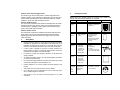
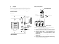
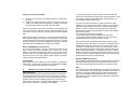
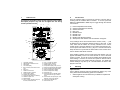
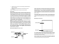
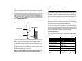
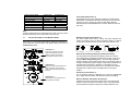
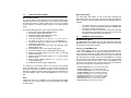
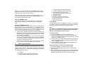
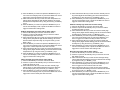
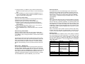
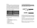
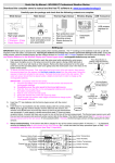
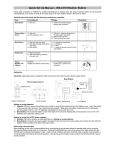
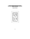
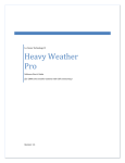
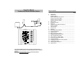
Operation Manual Professional Remote Weather Station Table of Contents 1. 2. 3. 4. 5. 6. WIRELESS WEATHER STATION This Operation Manual is part of this product and should be kept in a safe place for future reference. It contains important notes on setup and operation. Please see www.heavyweather.info for a complete IM, FAQ and downloads of the most current software. 7. 8. 9. 10. 11. 12. 13. 14. 15. 16. 17. 18. 19. 20. 21. 22. Page Introduction……………………………………………….......... Intended use…………………………………………………….. Weather Station…………… ................................................. System requirements for PC use…………........................... Features of the base station………… .................................. Features of the wind sensor………… .................................. Features of the rain sensor .................................................. Safety Notes ........................................................................ Packaged contents .............................................................. Setting up............................................................................. Operation using cable connection or wireless 433MHz ................................................................. LCD overview ...................................................................... Function test ........................................................................ Mounting .............................................................................. Resetting & factory settings ................................................. Function description............................................................. Operation keys..................................................................... Basic programming modes .................................................. MIN/MAX programming modes............................................ Alarm programming modes.................................................. Auto-memory for stored values............................................ Accessories: extensions cables ........................................... Changing batteries............................................................... Problems and interference with operation............................ Transmission range ............................................................. Cleaning and maintenance .................................................. Specifications....................................................................... 1. Introduction Thank you for purchasing this Professional Remote Weather Station. Designed for everyday use, the weather station will prove to be an asset of great value for your personal use in the home or office. Please read this instruction manual thoroughly to fully understand the correct operation of your weather station and benefit from its unique features. 2. Intended Use Weather Station The base station measures the indoor environment of its surrounding area and receives weather data from the following three outdoor sensors: 1) Thermo-Hygro Sensor 2) Wind Sensor 3) Rain Sensor The received data is continuously updated to bring you the latest weather information on the base station’s LCD. The outdoor thermohygro sensor is the main data communication unit since both the wind and rain sensors are connected to the thermo-hygro sensor for operating power and rely on it to communicate to the base station. Weather data sent from the thermo-hygro sensor can be done by wireless 433MHz transmission (up to 100ft in open space) or by cable connection. Using the enclosed 6.5ft computer cable and CD-ROM, you can install the Heavy Weather software to your PC and access the latest weather information from your PC and upload up to 175 sets of recorded weather data received by the base station. Recorded data can be used to generate statistics and charts onto your spreadsheets (175 sets of data is stored in the base even if the PC is switched OFF). The software itself does not set any limits as to how many data sets can be transferred to PC. This weather station is designed to work easily with your PC, simply connect and disconnect the PC cable at any time. System Requirements for PC use: The minimum system requirement for use of this “Heavy Weather” software is: Operating system: Windows 98 or above Processor: Pentium 166 MHz or above RAM: 32MB of RAM or above Hard disk: 20MB free space CD-ROM drive For full details on operation and installation of the “Heavy Weather” software refer to the PC manual in PDF format on the CD-ROM. Features of the base station: • • • • • • • • • • • • • • • • • Receives and displays the WWVB radio controlled time and date Display of extensive weather data, in all cases with programmable alarm functions for certain weather conditions as well as records of all minimum and maximum values along with time and date of their recordings Indoor and outdoor temperature displays in degrees Fahrenheit or Celsius (user selectable) Indoor and outdoor relative humidity displays Air pressure reading in inHg or hPa, absolute or relative (user selectable) Detailed display of rainfall data in 1 hour, 24 hours, total since last reset (user selectable in mm or inch) Wind speed in mph, km/h, m/s, knots or Beaufort (user selectable) Wind direction display with LCD compass as well as numerical (e.g. 225°) and abbreviated characters (e.g. SW) Wind chill temperature display Dew point temperature display Weather forecast display by weather icons (sunny, cloudy, rainy) Weather tendency indicator Storm warning alarm LED back light Simultaneous display of all weather data with individual settings by the user COM port for easy connection to your PC All the weather data from the base station and up to 175 sets of weather history data with user adjustable measuring intervals can be recorded and uploaded to your PC Features of the Thermo-Hygro Sensor The thermo-hygro sensor measures the outdoor temperature and relative humidity. It also collects the readings from the rain and wind sensors before transmitting the data to the base station by wireless 433MHz or by the 32ft cable included in this set. Features of Wind sensor The wind sensor measures wind speed and wind direction and sends the data to thermo-hygro sensor, which in turn transmits the data to the base station. Operating power is taken from the thermo-hygro sensor using a 32ft cable connection. Features of Rain sensor The rain sensor measures the rainfall and sends the data to thermohygro sensor, which in turn transmits the data to the base station. Operating power is taken from the thermo-hygro sensor by a 32ft cable connection. 3. • 4. Packaged Contents Before setting up, carefully unpack the contents onto a table or flat surface and check that the following are complete: Item: Consisting of: Fittings: Base Station • Main unit • AD/DC 120V power Adaptor - optional use (included) ThermoHygro Sensor • Main unit • Rain protection cover • 32ft cable - optional connection to the base station (included) • Wall mounting screws • Plastic anchors for screws Wind Sensor • Main unit with wind vane • 32ft cable (already attached to the main unit) • Mast holder • 2 x U-bolts for mast holder • 4 x Washers • 4 x Nuts • 1 x screw (to fix main unit to the mast holder Rain Sensor • Main unit (base and funnel) • 32ft cable (already attached to the main unit) Heavy weather PC software CD-Rom format (English and German language) Safety Notes Damage caused by failure to comply with this instruction manual will invalidate any guarantee! The manufacturer and supplier will not be held liable for damages due to failure to comply with this instruction manual or from data inaccuracies that may occur with this product! • In case of harm or damage to a person or property caused by improper handling or failure to comply with this instruction manual, the manufacturer and supplier cannot be held liable. • For reasons of safety and operation, alterations to this device are strictly prohibited. • To operate the weather station, use only supplied adaptor and batteries of the recommended type. • Do not leave discharged batteries in the device as these may corrode and release chemicals that may damage the unit. • Inserting batteries in an incorrect polarity will cause damage to this product. • This product is not a toy kept out of the reach of children. • Do not dispose of new or used batteries in a fire as they may explosion or release dangerous chemicals. • This product is not to be used for medical purposes or for public information. • 6.5ft PC cable for PC connection - optional use (included) Illustration: 5. Setting up Setting up using batteries: First, choose to use the adaptor (included in this set) or batteries for operation. Both these methods allow for operation using wireless 433MHz transmission or cable connection between the base station and the sensors and setting up for both methods is as follows: Thermo-Hygro Sensor Sensor sockets Base Station: Battery Compartment Battery Cover Socket for Adaptor Socket for Thermo-Hygro Sensor PC COM Port Sensor sockets Important: 1) 2) Battery compartment 3) 4) To avoid operating problems, please take note of battery polarity if inserting any batteries Pull away the rain cover of the thermo-hygro sensor to reveal the three sockets (for the wind sensor, rain sensor and the base station) Connect the attached cables of wind and rain sensors to the corresponding sockets of the thermo-hygro sensor by clicking them into place Open the battery cover of the thermo-hygro sensor located below the three sockets and insert 2 x AA, IEC LR6, 1.5V batteries and close the cover Open the base station’s battery cover located at the back of the unit and insert 3 x AA, IEC LR6, 1.5V batteries into the battery compartment and close the battery cover Setting up using the AC adaptor: 1) 2) Power up all the sensors as described in setting up using batteries above Using the AC adaptor (included), plug it into the mains outlet and power up the base station by inserting the adaptor jack into the DC 6.0V socket located on the side of the base station Every time the thermo-hygro sensor is powered up (for example after a change of batteries), a random security code is transmitted and this code must be synchronized with the base station to receive weather data. When the base station is powered up, a short beep will sound and all LCD segments will light up for about 5 seconds before it enters into a 15 minute learning mode to learn the sensors security code. After the learning mode (or by pressing the MIN/MAX key at anytime), the base station will start the WWVB radio controlled time reception. Note for WWVB Radio Controlled Time: The time and date display is based on the signal provided by the highly accurate government operated atomic clock in Ft. Collins, Colorado. This radio-controlled clock does not only provide for the weather station’s time and date display but also functions as the time and date source for all of this weather station’s memory and history values using time and date information. LCD backlight: When using the power adaptor, the LCD backlight is switched on continuously. Under battery operation, the LCD backlight is switched on for 15 seconds intervals when any key is pressed. 6. Operation using cable connection or wireless 433MHz Cable Connection: Using this method of operation will provide interference free transfer of the weather data from the sensors to the base station. The data sending interval from the sensors to the base station will also be more frequent compared to using 433MHz transmission and will result in higher power consumption. Therefore batteries will have a shorter life span for cable connection compared to using 433MHz. To operate using cable connection, simply use the enclosed 32ft cable and connect the thermo-hygro sensor to the base station. Once the connection is detected, the base station will automatically continue reading the data from the sensor. The user may at any time switch from cable connection to using 433MHz (or vice versa) by simply disconnecting (or connecting) the cable from the base station to the sensor. When the base station detects no cable connection to the sensors the base station will automatically change to using 433 MHz for reception of the weather data from the sensors. The data receiving intervals are as follows: -Using cable connection data is updated every 8 seconds. -Using wireless 433 MHz data is updated from 16 to 128 second intervals depending on wind speed and rain activity. Using the AC adaptor to operate the base station will also supply power to the sensor if the cable is connected to it. Batteries used for 433MHz transmission may be left in the sensor when using cable connection for power back up in case of AC power failure. A loss of power would desynchronize the base station and the sensor and no weather data will be received. To Synchronize the units so that the weather data can be received, press and hold the PLUS (+) key for 2 seconds. However in general, batteries that will not be used for long periods should be removed to avoid leakage. Wireless 433MHz transmission: Using 433MHz wireless transmission of weather data from the sensor to the base station will provide users greater freedom as to where units can be positioned without the need to be restricted by cable. Note: If no outdoor weather data is displayed or the signal to the sensors is lost during setting up, mounting, changing of batteries to the sensor or plugging or unplugging cables, simply press and hold the PLUS (+) key for 2 seconds and a short beep will sound to synchronize the base station to sensors. Without being synchronized, weather data will not be received. 7. LCD Overview The following illustration shows the full segments of the LCD for description purposes only and will not appear like this during normal operation and use. 1 2 3 4 1) 2) 3) 4) 5) 6) 7) 8) 9) 5 6 7 8 9 10 11 12 19 21 13 14 20 15 22 16 24 17 23 18 25 27 26 1. 2. 3. 4. 5. 6. 7. 8. 9. 10. 11. 12. 13. 14. Low battery indicator WWVB radio controlled time icon Date display Time zone display Date, seconds, alarm time and time zone Alarm icon Weather forecast icons Weather tendency indicator Pressure alarm display hPa/inHg air pressure unit Pressure units (relative or absolute) 433MHz reception icon Rainfall display Indoor, outdoor, humidity, dew point, wind chill, rainfall alarm icon 15. 16. 17. 18. 19. 20. 21. 22. 23. 24. 8. Function test: Once the weather station is powered up, perform a function test by checking that the weather data is received. To do this, press the DISPLAY, PRESSURE or WIND keys to toggle through the relevant LCD sections: 24h, 1h or total hour display Humidity display as RH% Rainfall units (inch or mm) Temperature display units (ºC or ºF) Outdoor temperature/humidity display Indoor temperature/humidity display Dew point temperature display Wind chill temperature display Wind alarm icon Wind information for Min/Max speed and wind speed low, high, direction alarm 25. Wind direction and speed (m/s, knots, Beaufort, km/h or mph) display 26. Alarm buzzer ON/OFF icon 27. General alarm icon Indoor temperature and humidity Outdoor temperature and humidity Outdoor wind chill Dew point Rainfall 24 hour Rainfall 1hour Rainfall Total Relative and absolute pressure Wind speed, wind direction and wind direction in degrees If any readings cannot be received from the sensors, lines (- - -) will be displayed in the respective weather sections of the LCD. In this case, check that all cables are correctly inserted into the correct sockets and/or check the batteries in the outdoor thermo/hygro sensor and press and hold the PLUS (+) key for 2 seconds and a short beep will sound to synchronize the base station to the sensors otherwise no weather data will be received. Some weather readings such as wind speed and direction may not appear immediately on the LCD if the wind-fan or vane of the wind sensor is moved. This is due to the set reading time intervals for the wind readings. However the current wind speed or direction will be displayed once the time reading interval is reached. For rainfall, the interval readings may take up to 2 minutes before the data is displayed on the LCD. 9. Mounting Important Note Prior to drilling mounting holes and permanently affixing any of the units, please ensure the following points are considered: • Cable lengths of the units meet with your distance requirements at the point of fixing • Signals from the sensors can be received by the base station at points of mounting • Radio controlled time signal can be received at the point of mounting NOTE: The WWVB receiver is located in the base station. Base Station With two foldable legs at the back of the unit, the base station can be placed onto any flat surface or wall mounted at the desired location by the hanging holes also at the back of the unit. It is important to check that the 433MHz (if using wireless connection) and the WWVB radio controlled time signal can be received before permanently mounting any of the units. Should the base station not display the 433MHz weather data from the sensors or the radio controlled time from the desired location, then relocate the units. Once the signals are received, the system can be affixed. Also if you have selected to use cable connection, ensure that distances can reach all desired locations before affixing any unit permanently NOTE: For reception of WWVB time/date signal, do not mount the base station closer than 5 feet from a computer, florescent lights or other electrical appliances. Do not mount the base station on a wall that has metal heat/AC ductwork in the wall behind the base station. For best WWVB reception place the base station near a window facing Colorado. WWVB reception will be obtained easiest in the nighttime hours when the WWVB signal is strongest. Firstly, check that the wind-fan and the wind-vane can rotate freely before fixing the unit. For correct and accurate readings it is important to mount the sensor so that the front (marked E) is pointing in East-West direction. The wind sensor should now be mounted using the screw provided onto a mast to allow the wind to travel around the sensor unhindered from all directions (ideal mast size should be from Ø.63” – Ø1.3”). Once the wind sensor is fixed onto the mast, connect the cable to the corresponding thermo-hygro sensor socket so that operating power supply can be received and data can be transmitted to the base station. Mounting the Rain Sensor Funnel portion Mounting the Wind Sensor onto a mast Base portion Wind-vane Mast Wind-fan For accurate results, the rain sensor should be securely mounted onto a horizontal surface about 2-3ft above the ground and in an open area away from trees or other coverings where rainfall may be reduced causing inaccurate readings. When securing into place, check that rain excess will not collect and store at the base of the unit but can flow out between the base and the mounting surface (test by pouring clean water). After mounting the rain sensor, connect the cable to the thermo-hygro sensor at the corresponding socket so power supply can be received and data be transmitted to the base station The rain sensor is now operable. For testing purposes, very slowly pour a small amount of clean water into the rain sensor funnel. The water will act as rainfall and will be received and displayed at the base station after about 2 minutes delay i.e. when the reading interval is reached (to clear this testing data on the base station, refer to the section “MIN/MAX Mode” below). Mounting the thermo-hygro Sensor Wall Bracket Rain Cover 10. Resetting & factory settings: As previously mentioned, in the event of a power reset to the sensor (for example a change of batteries), the base station has to synchronize to the sensor again otherwise no weather data will be received. To do this, simply press and hold the PLUS (+) key for 2 seconds and a short beep will sound to synchronize the base station to the sensor. When the units are synchronized, the data will be received again and the base station will return to normal operation mode. Do not remove batteries or unplug the AC adaptor of the base station otherwise all 175 sets of recorded weather history data for transferring to the PC will be lost (for full details of PC use, please see PC user manual in the enclosed Heavy Weather CD-ROM). However if you wish to make a full reset of the base station and return to the original factory settings, simultaneously press and hold the PRESSURE and WIND keys for about 5 seconds. The base station will beep once and the entire LCD will light up for 5 seconds and go back to the original factory settings. This process with clear all previous user defined values and all weather history recordings. Factory default settings: Main Unit An ideal mounting place for the thermo-hygro sensor would be the outer wall beneath the extension of a roof, as this will protect the sensor from direct sunlight and other extreme weather conditions. To wall mount, use the 2 screws to affix the wall bracket to the desired wall, plug in the thermo-hygro sensor to the bracket and secure both parts by the use of the supplied screw and ensure that the cables from the wind and rain sensors are correctly plugged in otherwise data transmission errors could occur. NOTE: For best 433 MHz reception mount the thermo-hygro sensor on an outside wall near the location of the base station. The following table shows the factory default values of the weather station: Matter: Time Date Time zone Alarm time Relative air pressure Weather-picture threshold LCD contrast level Rainfall per impulse Storm alarm Relative air pressure alarm Indoor temperature alarm Outdoor temperature alarm Default Setting: 0:00 01.01.2001 -5 ET 12:00 am 29.91 inHg 0.09 inHg 5 (1-8 levels) 0.0204 inches 0.09 inHg 28.34 inHg (low) 50ºF (low) 32ºF (low) 30.71 inHg (high) 86ºF (high) 104ºF (high) Indoor humidity alarm Outdoor humidity alarm Wind chill alarm Dew point alarm Rainfall 24h alarm Rainfall 1h alarm Wind Speed Wind direction alarm 35%RH (low) 45%RH (low) 50ºF (low) 32ºF (low) 1.96 inches 0.03 inches 1.0 mph (low) None set 65%RH (high) 70%RH (high) 86ºF (high) 68ºC (high) 62 mph (high) Time & Date (LCD Section 1) If the WWVB icon (icon 2) is ON and not flashing, it means that the WWVB radio-controlled time and date are has been received. Press the PLUS (+) key to change the format of date display between date/month/year, weekday/date/month, seconds, alarm set time and time zone. Note: All alarm default values are deactivated at the start up and any alarm must be activated by the user otherwise it will not sound. 11. Function Description of the Weather Station After setting up, the following data will be displayed in different sections on the LCD. If this is not the case please observe the notes on “Interferences” below. LCD Section 1: Time, date, seconds, time zone, weather forecasting icons with tendency arrows, air pressure, and respective alarms sections LCD Section 2: Indoor and outdoor temperature and relative humidity, wind chill, dew point, rainfall, and respective alarms sections LCD Section 3: Wind direction, wind speed, and respective alarms sections Weather forecasting (LCD Section 1) The three weather icons Sunny, Cloudy and Rainy represent the weather forecasting. There are also two weather tendency indicators to show the air pressure tendency either side of the weather icons. Sunny Cloudy Rainy Notes to hPa sensitivity setting for weather forecasting: The hPa (Hekto-Pascal) pressure sensitivity can be set to suit the user’s requirement for weather forecasting from 6 inHg, 9 inHg to 12 inHg (see Basic Programming below). For areas that experience frequent changes in air pressure (which does not necessarily reflect a change in the weather) requires a higher inHg setting compared to an area where the air pressure is stagnant. For example if 6 inHg is selected, then there must be a fall or rise in air pressure of at least 6 inHg before the weather station will register this as a change in weather. Air Pressure (LCD Section 1) The air pressure reading is displayed here. Press the PRESSURE key to toggle between relative and absolute air pressure displays. Notes to Absolute and Relative Air Pressure: Absolute air pressure provides the display of the true measured air pressure of the current time and location. This is not programmable and the absolute air pressure range of the weather station is from 8.85 inHg to 32.45 inHg (standard air pressure at an altitude of 30,000ft is around 8.85 inHg). Relative air pressure is the one value that is calculated back to sea level from the local absolute air pressure and can thus be taken as a reference for weather condition and weather development for the entire country. It can be programmed to represent your local surroundings. Since the relative air pressure is also the one value given by various newspapers, TV and radio broadcasting stations in their daily weather forecasts for their respective locations, users can set the relative air pressure of the weather station to this value to represent readings your their area (see Basic Programming Modes below). Weather Data (LCD Section 2) Indoor temperature and humidity are displayed simultaneously in this section. Use the DISPLAY key to toggle through the displays for other weather information: - Outdoor temperature/humidity - Outdoor wind chill - Outdoor dew point - Rainfall 24h - Rainfall 1h - Rainfall total. Notes to Dewpoint and Windchill: Air can at a certain temperature only carry a certain amount of water (water vapor), which also increases and decreases with temperature. If the air temperature decreases below the dewpoint (saturation point), the excessive water vapor will condense and fall out in form of dew, fog or rain. At a temperature of e.g. 59°F and a relative humidity of 50% the dewpoint will be about 41°F, at 80% humidity about 53.6°F. At a relative humidity of 100% saturation is reached, i.e. the dewpoint is 59°F. At a dewpoint below freezing the fallout will become frost or snow. Windchill has been introduced for battle planning during World War II. It represents not the real measured but the temperature a person feels in open area under the influence of wind and cold. Windchill is laid out in tables for various temperatures and wind speeds. At an outdoor temperature of e.g. 46.4°F and calm winds a person moving at a speed of 13 mph will already feel a windchill temperature of 32°F. Wind Data (LCD Section 3) The current wind direction will be displayed on the LCD compass on the wind section. Press the WIND key to toggle between wind direction as numerical (e.g. 225°) and abbreviated characters (e.g. SW) as well as numerical wind speed display inside the compass circle. 12. Operation keys ALARM - key The base station has 8 keys for easy operation. Please refer to the following table for use and function of each key: Further descriptions of the key functions with regard to their immediate range of application can be found in the Programming modes: SET - key PRESSURE - key DISPLAY - key WIND - key - In normal mode to enter the manual basic programming mode - In basic programming mode to select the following setting modes: - LCD contrast setting - Manual time setting (hours/minutes) - 12/24 time format display - Calendar setting (year/month/date) - Time zone setting - °C/°F temperature setting - Wind speed unit setting - Rainfall unit setting - Pressure unit setting - Relative air pressure setting - Weather picture threshold setting - Storm warning setting - Audible storm alarm setting - In setting modes confirmation of the selected values - In alarm modes alarm ON/OFF - In alarm mode to enter programming of alarm values (long pressing) - To exit MIN/MAX modes - Toggle between Absolute and Relative air pressure displays - Toggle between the following current/ maximum/ minimum display modes: - Indoor temperature and humidity - Outdoor temperature and humidity - Outdoor wind chill - Outdoor dew point - Rainfall (24h, 1h, total) To toggle between the following settings: - Wind speed - Wind direction - Wind direction display in degrees MIN/MAX - key PLUS (+) – key MINUS (-) – key - In normal mode to enter the alarm programming mode - In alarm programming mode to select the following setting modes: - Time alarm setting - Indoor temperature alarm (high & low) - Outdoor temperature alarm (high & low) - Indoor humidity alarm (high & low) - Outdoor humidity alarm (high & low) - Outdoor wind chill alarm (high & low) - Outdoor dew point alarm (high & low) - Rainfall alarm (24h, 1h) - Pressure alarm (high & low) - Wind speed alarm (high & low) - Wind direction alarm - In setting modes confirmation of the selected values - To exit MIN/MAX modes - To reset general alarm symbol - In normal display mode to toggle between display of MIN/MAX values - To toggle between MIN/MAX values in MIN/MAX mode - To exit any programming mode - In normal display mode to toggle between format of date display, seconds, time alarm and time zone - To increase the values in the setting modes - To exit MIN/MAX modes - In normal display mode to re-enter data learning mode (long pressing for 2 seconds) - In normal display mode to enable/disable the buzzer alarm (long pressing) - To decrease the values in the setting modes - In basic programming mode audible storm alarm ON/OFF - To snooze the alarms off 24 hours when the alarm is sounding - In MIN/MAX modes to reset recorded values and recorded dates and times 13. Basic Programming Modes Manual Setting modes The manual setting mode allows the user to change several basic settings, which is done by accessing one mode after the other simply by pressing the SET key. After the final mode, or if no key is pressed for 30 seconds, the manual setting returns to the normal display mode. The manual setting takes the user through the following modes: 1. 8 level LCD contrast setting (default level 5) 2. Manual time setting (hours/minutes) 3. 12/24h time display select (default 12 hours) 4. Calendar setting (year/month/date) 5. Time zone setting from 0 to +12 hrs, -1, -2, -3, AT -4, ET -5, CT -6, MT -7, PT -8, AL -9, HA -10, -11, -12 (default ET -5) 6. Temperature display unit degree Celsius or Fahrenheit (default degree Fahrenheit) 7. Wind speed display units in m/s, km/h, mph, Beaufort, knots (default setting mph) 8. Rainfall display in mm or inch (default setting inch) 9. Air pressure display in hPa or inHg (default setting inHg) 10. Relative air pressure setting from 27.10 inHg – 31.90 inHg (default 29.98 inHg) 11. Weather forecast sensitivity setting 6, 9, 12 inHg (default setting 9 inHg) 12. Storm warning sensitivity setting 9, 12, 15, 18, 21, 24, 29 inHg (default 9 inHg) 13. Audible storm alarm On/OFF (default ON) To change any of the above values, once your are in the setting mode, use the PLUS (+) or MINUS (-) keys to select the values followed by the SET key to enter the next setting. Continue to press the SET key to toggle through the setting mode until the LCD returns to the normal display mode or press the MIN/MAX key at any time to exit. Note! Keeping the PLUS (+) or MINUS (-) key depressed when setting certain units in the manual setting mode will increase/decrease digits in greater steps. Manual time setting The base station will continue to scan for the radio controlled time signal from 12am-6 am (1am-6pm summer time) each day despite it being manually set. During reception attempts the WWVB tower icon will flash. • • 14. If reception has been unsuccessful, then the WWVB tower icon will not appear but reception will still be attempted the following hour within the time frame If reception has been successful, the received time and date will overwrite the manually set time and date and no further reception is attempted until the following day MIN/MAX Programming Modes MIN/MAX display Mode The MIN/MAX Mode provides the user with information about the MIN/MAX values of all weather data together with the time and date at which these values were recorded. Entering each MIN/MAX mode In the normal display mode for e.g. the indoor temperature and humidity, press MIN/MAX key to toggle the display between the maximum, minimum and current records. While the maximum or minimum values are shown press the DISPLAY key once to show the time and date that value was received. Now press the MIN/MAX key to toggle from the minimum and maximum readings and the time and dates the records were received are also shown. Still in the MIN/MAX mode (where the time and date for a value are shown), press the DISPLAY key to move through each respective unit as follows: • • • • • • • • Indoor temperature (max or min with time and date) Indoor humidity (max or min with time and date) Outdoor temperature (max or min with time and date) Outdoor humidity (max or min with time and date) Outdoor wind chill (max or min with time and date) Outdoor dew point (max or min with time and date) Rainfall 24 hours (max or min with time and date) Rainfall 1 hour (max or min with time and date) • Rainfall total (max only with time and date) When in any of the above modes, press the MIN/MAX key to toggle between the maximum or minimum values of those records and their respective time and dates will also be shown. For the wind and pressure minimum and maximum readings, the same would apply except that the WIND or PRESSURE keys would be used instead of the DISPLAY KEY. Exiting the MIN/MAX modes If the maximum and minimum modes with times and dates are displayed, press the PLUS (+) key twice to return the normal display mode. Resetting the MIN/MAX records While in the minimum or maximum mode, the time and dates are also displayed along with the recorded values. If the MINUS (-) key is pressed while any of these values are displayed, that particular minimum or maximum record will be reset to current reading together with the current time and date with the exception of the following: The first case is Rainfall Total, which has neither maximum nor minimum records since it will show only the total rainfall. Pressing the MINUS (-) key will reset the rainfall total value to zero and the time recording to current time. The second case is Rainfall 24h or 1h, which records maximum rain count only for these respective times. Pressing the MINUS () key in either of these two modes will reset the rain count to the current rain count and time and date. The third case is wind speed, which will only reset the recorded time to current time when the MINUS (-) key is pressed. 15. Alarm Programming Modes Alarm Modes As well as the normal time alarm, this feature will allow users to set a range of specific alarms to meet specific weather and temperature conditions set by the user. The weather station allows for the following 13 alarms modes to be set: 1. 2. 3. Time alarm Indoor temperature high alarm and low alarm Outdoor temperature high alarm and low alarm 4. 5. 6. 7. 8. 9. 10. 11. 12. 13. Indoor humidity high alarm and low alarm Outdoor humidity high alarm and low alarm Wind chill high alarm and low alarm Dew point alarm high alarm and low alarm Rainfall 24h alarm Rainfall 1h alarm Pressure high alarm and low alarm Wind speed high alarm and low alarm Wind direction alarm Storm warning alarm Setting Alarms: For alarm setting, press the ALARM key once while in normal operation mode to enter the normal alarm time and by further pressing the ALARM key will toggle through each of the alarm modes: Note: The alarm icon will automatically appear upon pressing the SET key to tell the user the alarm is activated. Further pressing the SET key will deactivate/reactivate the alarm. Time alarm setting 1) Press the ALARM key to enter the normal time alarm 2) Press and hold the SET key to enter the alarm hour time set mode (the hour digits will flash) and set the desired hour by using the PLUS (+) or MINUS (-) keys 3) Press the SET key to enter the alarm minute time set mode (the minutes digits will flash) and set the desired minutes using the PLUS (+) or MINUS (-) keys 4) Press ALARM key to confirm followed by the MIN/MAX key to return to the normal display mode. Indoor temperature high alarm and low alarm setting 1) Press the ALARM key to enter the normal time alarm 2) Press the ALARM key again to enter indoor temperature high alarm set mode 3) Press and hold the SET key to enter the indoor temperature high setting values (digits will start flashing) and set the desired indoor temperature high by using the PLUS (+) or MINUS (-) keys 4) Press ALARM key to confirm and press the MIN/MAX key to return to the normal display mode or press the ALARM once more to toggle to the indoor temperature low alarm set mode. 5) Press and hold the SET key to enter the indoor temperature low setting values (temperature digits will start flashing) and set the desired indoor temperature low by using the PLUS (+) or MINUS () keys 6) Press ALARM key to confirm and press the MIN/MAX key to return the normal display mode or press the ALARM once more to toggle to another alarm setting mode. Outdoor temperature high alarm and low alarm setting 1) Press the ALARM key to enter the normal time alarm 2) Continue to press the ALARM key until you reach the outdoor temperature high alarm set mode 3) Press and hold the SET key to enter the outdoor temperature high setting values (temperature digits will start flashing) and set the desired outdoor temperature high by using the PLUS (+) or MINUS (-) keys 4) Press ALARM key to confirm and press the MIN/MAX key to return to the normal display mode or press the ALARM once more to toggle to the outdoor temperature low alarm set mode. 5) Press and hold the SET key to enter the outdoor temperature low setting values (digits will start flashing) and set the desired outdoor temperature low by using the PLUS (+) or MINUS (-) keys 6) Press ALARM key to confirm and press the MIN/MAX key to return the normal display mode or press the ALARM once more to toggle to another alarm setting mode. Indoor humidity high alarm and low alarm setting 1) Press the ALARM key to enter the normal time alarm 2) Continue to press the ALARM key until you reach the indoor humidity high alarm set mode 3) Press and hold the SET key to enter the indoor humidity high setting values (% digits will start flashing) and set the desired indoor humidity high by using the PLUS (+) or MINUS (-) keys 4) Press ALARM key to confirm and press the MIN/MAX key to return to the normal display mode or press the ALARM once more to toggle to the indoor humidity low alarm set mode. 5) Press and hold the SET key to enter the indoor humidity low setting values (digits will start flashing) and set the desired indoor humidity low by using the PLUS (+) or MINUS (-) keys 6) Press ALARM key to confirm and press the MIN/MAX key to return the normal display mode or press the ALARM once more to toggle to another alarm setting mode. Outdoor humidity high alarm and low alarm setting 1) Press the ALARM key to enter the normal time alarm 2) Continue to press the ALARM key until you reach the outdoor humidity high alarm set mode 3) Press and hold the SET key to enter the outdoor humidity high setting values (digits will start flashing) and set the desired outdoor humidity high by using the PLUS (+) or MINUS (-) keys 4) Press ALARM key to confirm and press the MIN/MAX key to return to the normal display mode or press the ALARM key once more to toggle to the outdoor humidity low alarm set mode. 5) Press and hold the SET key to enter the outdoor humidity low setting values (digits will start flashing) and set the desired outdoor humidity low by using the PLUS (+) or MINUS (-) keys 6) Press ALARM key to confirm and press the MIN/MAX key to return the normal display mode or press the ALARM once more to toggle to the to enter another alarm setting mode. Wind chill high alarm and low alarm setting 1) Press the ALARM key to enter the normal time alarm 2) Continue to press the ALARM key until you reach the wind chill high alarm set mode 3) Press and hold the SET key to enter the wind chill high setting values (digits will start flashing) and set the desired wind chill high by using the PLUS (+) or MINUS (-) keys 4) Press ALARM key to confirm and press the MIN/MAX key to return to the normal display mode or press the ALARM key once more to toggle to the wind chill low alarm set mode. 5) Press and hold the SET key to enter the wind chill low setting values (digits will start flashing) and set the desired wind chill low by using the PLUS (+) or MINUS (-) keys 6) Press ALARM key to confirm and press the MIN/MAX key to return the normal display mode or press the ALARM once more to toggle to another alarm setting mode. Dew point alarm high alarm and low alarm setting 1) Press the ALARM key to enter the normal time alarm 2) Continue to press the ALARM key until you reach the dew point high alarm set mode 3) Press and hold the SET key to enter the dew point setting values (digits will start flashing) and set the desired dew point high by using the PLUS (+) or MINUS (-) keys 4) Press ALARM key to confirm and press the MIN/MAX key to return to the normal display mode or press the ALARM key once more to toggle to the dew point low alarm set mode. 5) Press and hold the SET key to enter the dew point low setting values (digits will start flashing) and set the desired dew point low by using the PLUS (+) or MINUS (-) keys 6) Press ALARM key to confirm and press the MIN/MAX key to return the normal display mode or press the ALARM once more to toggle to another alarm setting mode. Pressure high alarm and low alarm setting 1) Press the ALARM key to enter the normal time alarm 2) Continue to press the ALARM key until you reach the pressure high alarm set mode 3) Press and hold the SET key to enter the pressure setting values (digits will start flashing) and set the desired pressure high by using the PLUS (+) or MINUS (-) keys 4) Press ALARM key to confirm and press the MIN/MAX key to return to the normal display mode or press the ALARM key once more to toggle to the pressure low alarm set mode. 5) Press and hold the SET key to enter the pressure low setting values (digits will start flashing) and set the desired pressure low by using the PLUS (+) or MINUS (-) keys 6) Press ALARM key to confirm and press the MIN/MAX key to return to the normal display mode or press the ALARM once more to toggle to another alarm setting mode. Rainfall 24h alarm setting 1) Press the ALARM key to enter the normal time alarm 2) Continue to press the ALARM key until you reach the rain 24 hour alarm set mode 3) Press and hold the SET key to enter the rain setting values (digits will start flashing) and set the desired rain values by using the PLUS (+) or MINUS (-) keys 4) Press ALARM key to confirm and press the MIN/MAX key to return to the normal display mode or press the ALARM key once more to toggle to another alarm setting mode. Wind speed high alarm and low alarm setting 1) Press the ALARM key to enter the normal time alarm 2) Continue to press the ALARM key until you reach the wind speed high alarm set mode 3) Press and hold the SET key to enter the wind speed setting values (digits will start flashing) and set the desired wind speed high by using the PLUS (+) or MINUS (-) keys 4) Press ALARM key to confirm and press the MIN/MAX key to return to the normal display mode or press the ALARM key once more to toggle to the wind speed low alarm set mode. 5) Press and hold the SET key to enter the wind speed low setting values (digits will start flashing) and set the desired pressure low by using the PLUS (+) or MINUS (-) keys 6) Press ALARM key to confirm and press the MIN/MAX key to return the normal display mode or press the ALARM once more to toggle to another alarm setting mode. Rainfall 1h alarm setting 1) Press the ALARM key to enter the normal time alarm 2) Continue to press the ALARM key until you reach the rain 1 hour alarm set mode 3) Press and hold the SET key to enter the rain setting values (digits will start flashing) and set the desired rain values by using the PLUS (+) or MINUS (-) keys 4) Press ALARM key to confirm and press the MIN/MAX key to return to the normal display mode or press the ALARM key once more to another alarm setting mode. Wind direction alarm setting 1) Press the ALARM key to enter the normal time alarm 2) Continue to press the ALARM key until you reach the wind direction alarm set mode 3) Press and hold the SET key to enter the wind direction setting values. 4) Using the PLUS (+) or MINUS (-) keys select the desired wind direction and use the SET key to confirm or cancel each direction input 5) Press ALARM key to confirm and press the MIN/MAX key to return the normal display mode or press the ALARM once more to toggle to another alarm setting mode. Storm warning alarm setting Unlike the other weather alarms, the storm warning alarm is set by entering the main manual setting mode as follows: 10) Press the SET key to enter the manual setting mode 11) Continue to press the SET key until the Storm warning icon flashes (tendency arrow flashing downwards with the pressure values flashing) 12) Set the desired inHg pressure value (9, 12, 15, 18, 21, 24, 27 inHg) using the PLUS (+) or MINUS (-) keys 13) Press the MIN/MAX key to confirm and return to the normal display. Storm warning alarm ON/OFF After storm warning alarm setting, the next mode to appear after pressing the SET key is the storm warning ON/OFF. Use the PLUS (+) or MINUS (-) key to change the status to AON or AOFF. Default setting is ON: Should the air pressure drop equal or below the pre-set inHg value within the last 6 hour period, then the downward tendency arrow will flash as an indication of possible storm. The base station will take hourly measurements as a point of reference. The storm-warning indicator will stop flashing once the air pressure becomes more stable. Master Alarm – BUZZER OFF The time and all the weather alarms may have buzzer sound set to OFF by holding the MINUS (-) key down for about 3 seconds in normal display mode and the BUZZER OFF icon appears on the bottom left of the LCD. When the BUZZER OFF is displayed, the time and all other weather alarms when activated will only flash but not sound regardless if that particular alarm has been set to the ON. To deactivate the BUZZER OFF, press the MINUS (-) key once more. General Alarm Icon The general alarm icon on the bottom right corner of the LCD will appear when any weather alarm is activated to show the user that a set weather condition has been reached. The activated alarm can be determined by checking the set alarm values against the MIN/MAX values reached. To deactivate the general weather alarm icon, press the ALARM key. Important When entering the alarm set mode for a specific weather or temperature condition, the corresponding alarm is automatically enabled (ON) when the SET key is pressed, regardless of its previous setting and the alarm value will flash to indicate that it has been activated. Press the ALARM key to confirm the setting and continue pressing the ALARM key to toggle through each alarm mode until it returns to the normal display mode or press the MIN/MAX key at any time to exit the alarm setting modes. When a set weather alarm condition has been activated, that particular alarm will sound and flash for approximately 2 minutes but will continue to flash until weather conditions have become more steady. Weather Alarms The weather alarms are settable for when certain weather conditions are met according to the users requirements. For example, the user can set the thresholds for the outdoor temperature to +86°F (high) and 14°F (low), while only enabling the high alarm and disabling the low alarm (i.e. temperatures <-14°F won’t trigger alarm, but temperatures >+86°F will). Alarm setting Storm threshold Relative Air Pressure Outdoor Temperature Minimum 0.09 inHg 27.10 inHg -21.8°F Maximum 0.27 inHg 31.89 inHg +157.8°F Indoor Temperature 14.1°F. No alarm will sound if the minimum indoor temperature alarm is set below this value. 20% RH 0.0 inch 0.0 inch 0.0 mph +139.8°F Humidity (all) Rainfall 24h Rainfall 1h Wind 95% RH 39.37 inch 39.37 inch 111.8 mph Hysteresis To compensate for fluctuation of the measured data, which may cause the weather alarm to sound constantly if the measured reading is close to user set level, a hysteresis function has been implemented for each weather alarm. For example, if the high temperature alarm is set to +77°F and the current value moves to +78°F, the alarm will be activated (if it has been enabled). Now when the temperature drops to +76°F or below and thereafter again increases to beyond +77°F, the data will be blinking, but no alarm will be activated. It has to drop to below +75.2°F (with a pre-set hysteresis of 1.8°F) so that the alarm can be produced again. Hysteresis values for the various weather data types are given in the following table: Weather data Temperature Humidity Air pressure Rainfall 24h Rainfall 1h Wind 16. Hysteresis 1.8°F 3% RH 0.0295 inHg 0.1968 inch 0.01968 inch 3.1 mph Auto memory for stored values The base station has a memory back up system, which is used to memorize user-defined settings for when the batteries are changed or if a power failure occurs. User defined units are automatically updated each time these are changed. The base station will memorize the following user defined units: • • • • • • • • • • • Time zone 12/24h time display mode Unit settings (temperature, pressure, rainfall, wind) Air pressure offset for calculation of relative air pressure Weather picture threshold Storm warning threshold LCD contrast Alarm time Weather Alarm thresholds State of alarms (enabled/disabled) Rainfall total value and reset time/date 17. Accessories: adding cable extensions For your convenience, additional telephone cables to increase the connection distance between each of the units may be purchased from any reputable hardware store. Simply add these to the current cables to extend your cable connection distance. Telephone Extension Cables When securing the cables during mounting, ensure that base station can receive the weather data since increasing the cables lengths may also increase levels of interference and result with reception difficulties. Interference levels will greatly depend on the surrounding area for example setting up on or near metal piping may considerably reduce reception. For best results, do not to add more than 32ft of extension cable from item to item onto the existing cable lengths as this may reduce reception levels. Again, reception and interference levels will greatly depend on the surrounding environment at your point of mounting. Note: It is important to keep all the connected extension heads away from rain, moisture and other extreme weather conditions as exposure can cause short circuits and damage to this item. 18. Changing batteries: Battery change only in the thermo-hygro-sensor: 1. Open the battery cover 2. Remove the old batteries and insert with new ones of the recommended type and replace the cover Once the sensor is powered up, press and hold the PLUS (+) key for approx. 2 seconds in the normal display mode, the base station will sound a short beep and synchronize to the sensor otherwise no weather data will be received. Battery change only in the base station: 1. Connect power adaptor to base station and power outlet. 2. Open the battery cover located at the back of the base station. 3. Remove the old batteries, insert with new ones of the recommended type and replace the cover This method of battery replacement will result in no loss of MIN/MAX and history data. However in case of possible power failure, the base station will lose the MIX/MAX and all weather data recordings and will need to be synchronized to the sensors again by pressing the PLUS (+) key for 2 seconds. Note: When batteries require replacement for the base station, the low battery indicator will light up on the LCD. Please participate in the preservation of the environment by properly disposing of all used-up batteries and accumulators at designated disposal points. Never dispose of batteries in a fire as this may cause explosion, risk of fire or leakage of dangerous chemicals and fumes 19. Interferences and problems with operation Problem & cause Distance between transmitters and receiver too long. Remedy Reduce distance between transmitters and receiver to receive signal High shielding materials between the units (thick walls, steel, concrete, isolating aluminum foil and etc.) Find a different location for sensors and/or receiver. See also Item ‘Transmission Range’ below. Interference from other sources (e.g. wireless radio, headset, speaker, etc. operating on the same frequency) No Reception after adding extension cables Find a different location for the sensors and/or base station. Neighbors using electrical devices operating on the 433MHz signal frequency can also cause interference with reception Find a new location for the sensors and/or base station. Recommend not adding more than 32ft extension cables between units to the existing cable lengths, as this will increase the chance of data reception problems. Press and hold the PLUS (+) key for 2 seconds to synchronize the base station to the sensors for weather data reception. If still no signal, then change the sensor batteries and synchronize the units again. Check the LCD contrast setting or change batteries (check low battery indicator on the LCD) Reception then no reception - loss of transmission signal from the sensor to the base station Poor contrast LCD or no reception or low batteries in sensors or receiver. Quite frequently interferences are only of a temporary nature and may be easily overcome. If there are wireless headsets, remote babysitters or other devices working on 433MHz in your house or in the vicinity, their switch-on time is mostly limited. Furthermore most of these devices allow the change to an interference-free frequency. Such measures will effectively overcome interferences. 20. Transmission Range The transmission distance from the thermo-hygro sensor to the base station in open space under optimum conditions is 100ft. Although the signal transmission may travel though solid surfaces or objects, the following points should be avoided if possible: - - 21. - - - High frequency interferences of any kind. High densities of trees. Broadband interferences in municipal areas can reach levels reducing the signal/noise ratio over the entire frequency band, thus also reducing the transmission distance. Devices working close by (example a neighbor’s house) may also influence reception. Poorly shielded PCs can cause interferences that will reduce or in some cases stop reception The transmitter and receiver should not be mounted on metal surfaces as this will reduce transmission range. 22. Specifications Outdoor data Transmission Distance in Open Field: Temperature Range : Resolution Measuring Range Rel. Humidity : : Rain Volume Display : Resolution Wind Speed Resolution Wind Direction : : : : Cleaning and Maintenance Clean the housing and screen of the base station only with a soft damp cloth. Do not use abrasives or solvents. Ensure that the rain sensor does not collect leaves or other dirt by checking the funnel for blockages every now and then. Also clean the seesaw of the sensor with a damp cloth and check by lightly tapping with your finger that it can move freely from side to side. Do not clean the funnel with the bottom half of the rain sensor attached nor the bottom part itself under running water. This may bear the danger of water entering the unit’s inner parts and cause damages. Do not immerse the base station in water. Should there be damage to this product, please do not attempt to make any repairs. Please take this unit to a qualified technician. Opening or improper handling of the units will invalidate any guarantee. 100ft max. -21.8°F to +157.8°F (show OFL” if outside range) 0.2°F 20% to 95% (if the relative humidity is less than 20% or greater than 95%, it will display 19% or 96%) 0 to 39.37 inches (1h and 24h rainfall) 0 to 98.38 inches (Total rainfall) 0.1mm 0 to 111.8 mph 0.1 mph Graphic Resolution 22.5 Degrees, Numerical Resolution, Letter format Using 433MHz wireless data transmission: Measuring interval thermo-hygro sensor : 32 sec (if wind factor>22.36 mph) or 128sec (if wind factor< 22.36mph) 10 minutes (if the base station fails to receive any data after 5 attempts in a row, all outdoor data readings will display “---“, except for the rain value) With cable connection for data transmission: Measuring interval thermo-hygro sensor : 8 seconds Indoor data Pressure/ temperature Indoor Temperature Range : : Resolution : 4 times per minute 14.1°F to + 139.8°F (shows “OFL” if outside range) 0.2°F Measuring Range Rel. Humidity : Resolution Measuring Range Air Pressure : : Resolution Relative humidity checking interval . : 20% to 95% (if the relative humidity is less than 20% or greater than 95%, it will display 19% or 96%) 1% 8.85 inHg to 32.45 inHg (Standard air pressure at an altitude of 30,000 ft is around 8.85 inHg) 0.01 inHg every 30 seconds Alarm duration : 2 minutes (approx.) Power consumption Base Station Batteries : or AC power : Thermo-hygro sensor : Battery life using 433MHz: : approximately 12 months (alkaline batteries recommended) Battery life using cable connection : approximately 6 months (alkaline batteries recommended) Dimensions (L x W x H): Base Station Thermo-hygro sensor Rain sensor Wind sensor : : : : 3 x AA, IEC LR6, 1.5V (Alkaline recommended) INPUT 120V AC 60HZ (use the provided AC/DC adapter only) 2 x AA, IEC LR6, 1.5V (or can draw power from the adapter if used) 170 x 35 x 138 inches 71.5 x 73 x 136 inches 140 x 70 x 137 inches 60 x 197 x 291 inches WARRANTY INFORMATION La Crosse Technology, Ltd provides a 1-year limited warranty on this product against manufacturing defects in materials and workmanship. This limited warranty begins on the original date of purchase, is valid only on products purchased and used in North America and only to the original purchaser of this product. To receive warranty service, the purchaser must contact La Crosse Technology, Ltd for problem determination and service procedures. Warranty service can only be performed by a La Crosse Technology, Ltd authorized service center. The original dated bill of sale must be presented upon request as proof of purchase to La Crosse Technology, Ltd or La Crosse Technology, Ltd’s authorized service center. La Crosse Technology, Ltd will repair or replace this product, at our option and at no charge as stipulated herein, with new or reconditioned parts or products if found to be defective during the limited warranty period specified above. All replaced parts and products become the property of La Crosse Technology, Ltd and must be returned to La Crosse Technology, Ltd. Replacement parts and products assume the remaining original warranty, or ninety (90) days, whichever is longer. La Crosse Technology, Ltd will pay all expenses for labor and materials for all repairs covered by this warranty. If necessary repairs are not covered by this warranty, or if a product is examined which is not in need or repair, you will be charged for the repairs or examination. The owner must pay any shipping charges incurred in getting your La Crosse Technology, Ltd product to a La Crosse Technology, Ltd authorized service center. La Crosse Technology, Ltd will pay ground return shipping charges to the owner of the product to a USA address only. Your La Crosse Technology, Ltd warranty covers all defects in material and workmanship with the following specified exceptions: (1) damage caused by accident, unreasonable use or neglect (including the lack of reasonable and necessary maintenance); (2) damage occurring during shipment (claims must be presented to the carrier); (3) damage to, or deterioration of, any accessory or decorative surface; (4) damage resulting from failure to follow instructions contained in your owner’s manual; (5) damage resulting from the performance of repairs or alterations by someone other than an authorized La Crosse Technology, Ltd authorized service center; (6) units used for other than home use (7) applications and uses that this product was not intended or (8) the products inability to receive a signal due to any source of interference.. This warranty covers only actual defects within the product itself, and does not cover the cost of installation or removal from a fixed installation, normal set-up or adjustments, claims based on misrepresentation by the seller or performance variations resulting from installation-related circumstances. LA CROSSE TECHNOLOGY, LTD WILL NOT ASSUME LIABILITY FOR INCIDENTAL, CONSEQUENTIAL, PUNITIVE, OR OTHER SIMILAR DAMAGES ASSOCIATED WITH THE OPERATION OR MALFUNCTION OF THIS PRODUCT. THIS PRODUCT IS NOT TO BE USED FOR MEDICAL PURPOSES OR FOR PUBLIC INFORMATION. THIS PRODUCT IS NOT A TOY. KEEP OUT OF CHILDREN’S REACH. This warranty gives you specific legal rights. You may also have other rights specific to your State. Some States do no allow the exclusion of consequential or incidental damages therefore the above exclusion of limitation may not apply to you. For warranty work, technical support, or information contact: La Crosse Technology, Ltd 2809 Losey Blvd. S. La Crosse, WI 54601 Phone: 608.782.1982 Fax: 608.796.1020 e-mail: [email protected] (warranty work) [email protected] (information on other products) web:www.lacrossetechnology.com