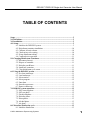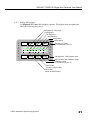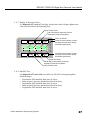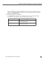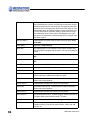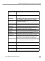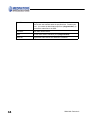
1
User Manual
Single-shot
Generator Kit for
DSD-201™
DSD-91E™
Endoscope Reprocessors
50090-946 Revision A
©2003, Medivators Reprocessing Systems
a Minntech Corporation Business Group
50090-946 Revision A
All rights reserved. This publication is protected by copyright.
Copying, disclosure to others, or the use of this publication is
prohibited without the express written consent of Medivators
Reprocessing Systems.
Medivators Reprocessing Systems reserves the right to make changes
in the specifications shown herein without notice or obligation.
Contact your representative or Medivators customer service for more
information.
DSD-201™/DSD-91E Single-shot Generator User Manual
TABLE OF CONTENTS
Scope ...................................................................................................................................3
2.0 Definitions....................................................................................................................3
3.0 Installation ...................................................................................................................3
4.0 Setup.............................................................................................................................3
4.1 Initialize the DSD/SSG system.........................................................................3
4.2 Disinfectant container installation. .................................................................10
4.3 Calibrate A-basin volume. ..............................................................................10
4.4 Check mixer valve setting...............................................................................10
4.5 Prime disinfectant tubing. ...............................................................................10
4.6 Confirm device operation. ..............................................................................11
5.0 Changing Disinfectant Containers ..........................................................................11
5.1 Disconnect lance(s).........................................................................................11
5.2 Dispose of container. ......................................................................................11
5.3 Disinfect part B lance. ....................................................................................11
5.4 Install new container. ......................................................................................11
5.5 Clear disinfectant cycle count.........................................................................11
6.0 Using the DSD/SSG system. .....................................................................................11
6.1 Pre-clean endoscope. ......................................................................................11
6.2 Load endoscope. .............................................................................................12
6.3 Select station. ..................................................................................................12
6.4 Select program. ...............................................................................................12
6.5 Enter data. .......................................................................................................12
6.6 Start the reprocessor........................................................................................12
6.7 Remove endoscope. ........................................................................................12
7.0 DSD/SSG system operation......................................................................................12
7.1 SSG warm-up phase........................................................................................12
7.2 SSG test phase ................................................................................................12
7.3 Flush/wash phase. ...........................................................................................13
7.4 Disinfect phase................................................................................................13
7.5 Rinse phases....................................................................................................13
7.6 Alcohol phase. ................................................................................................13
7.7 Air phase. ........................................................................................................13
8.0 Waterline disinfection cycle. ....................................................................................13
8.1 Initialize disinfection. .....................................................................................13
© 2003 Medivators Reprocessing Systems
1
8.2 Connect restrictor............................................................................................13
8.3 Water line disinfection....................................................................................13
9.0 New and modified setups/diagnostics......................................................................14
9.1 Software version. ............................................................................................14
9.2 Display temperature. .......................................................................................14
9.3 Clear print queue.............................................................................................15
9.4 Set automatic printing enable. ........................................................................16
9.5 Set SSG water mixer valve temperature. ........................................................16
9.6 Prime disinfectant tubing. ...............................................................................16
9.7 Calibrate basin A volume. ..............................................................................16
9.8 Display all SSG/DSD inputs...........................................................................17
9.9 Disinfectant Setup...........................................................................................17
9.10 Set SSG PWM rates for chemical pumps .....................................................18
9.11 Special SSG/IIC commands..........................................................................18
9.12 SSG turbine calibration.................................................................................28
9.13 SSG temperature circuit calibration..............................................................28
9.14 Reservoir low/high level sense inhibit..........................................................29
9.15 SSG Sensor Inhibit........................................................................................30
9.16 DSD/SSD swap.............................................................................................30
Warranty ........................................................................................................................35
2
50090-946 Revision A
DSD-201™/DSD-91E Single-shot Generator User Manual
1.0 Scope
This document is used with the SSG option for the DSD-91E and DSD-201 high-level
disinfectors, and is intended as an addendum to the existing manuals.
2.0 Definitions
DSD
Dual-sided Disinfector (e.g., DSD-91E or DSD-201)
SSG
Single-shot Generator (purchased with this kit)
3.0 Installation
Installation of kit components:
DSD-201 per 50090-944
DSD-91E per 50090-945
4.0 Setup
These steps are required in sequence to set up the DSD/SSG system after installation.
Note: To enter the diagnostics mode, enter Setup #88 with input code 135.
4.1 Initialize the DSD/SSG system.
4.1.1 Initialize NVRAM.
Perform diagnostic #86 to initialize all program settings.
Note: If this is done later, it will erase all user logs, settings, and programs.
4.1.2 Set serial number.
Perform diagnostic #82 to enter the last four digits of the DSD serial number, which
can be found on the left inside panel of the cabinet.
PROMPT
ENTER
Input S/N Major
Middle two digits of the serial number.
Input S/N Minor
Last two digits of the serial number.
4.1.3
Set options.
Perform diagnostic #88 to set the DSD system options.
Note: This must be performed on both stations. Set to 1 if machine is equipped with option:
otherwise, set to 0.
PROMPT
ENTER
Leak Test Option
Sheath integrity test option.
Recirc Option
Basin water recirculation option (DSD-201 only,
set to 0 for DSD-91E).
© 2003 Medivators Reprocessing Systems
3
4
Auto Dis. Option
Automated waterline disinfection option - set to 1
when SSG option is installed.
Heat Option
Heated disinfectant reservoir option - set to 0
when SSG option is installed.
SSG Option
Single-shot use chemistry option - set to 1 when
SSG option is installed.
Temp Option
Basic temperature monitoring option.
50090-946 Revision A
DSD-201™/DSD-91E Single-shot Generator User Manual
4.1.4
System cycle times.
The default cycle times are for the standard DSD-201 and will require modification
for the SSG installation. Use the times shown below as a starting point and then
adjust to an appropriate value for the system Use the default times for a DSD-201.
Use the times below for the DSD-91E.
Diagnostic
Name
Description
DSD-201
Default
Value
Initial
Value
DSD-91E
61
Rinse Drain
Time
Rinse water drain time with water purge
through scope channels. A 30-second
drain without water purge follows this. If
this is set too short, water will remain in
the basin when the next phase starts.
60 seconds
70
61
Disinfectant
Drain Time
Disinfectant drain time. If this is set too
short, disinfectant will remain in the basin
when the rinse phase starts.
90 seconds
default
62
Rinse Fill
Time
This is the portion of the rinse fill phase
that is required prior to checking for the
level switch. If your facility has low water
pressure and the DSD is getting Low
Chamber errors, extend this time.
90 seconds
140
62
Disinfectant
Fill Time
Not used with SSG option, this time is
hard-coded to 12 minutes.
70 seconds
n/a
63
Fluid Purge
Time
This is the amount of time the scope
channels are purged with rinse water
before each of the rinse phases.
30 seconds
default
63
Air Purge
Time
30 secThis is the amount of time the scope
channels are purged with air after the dis- onds
infect phase and each of the rinse
phases.
default
64
Disinfectant
pulse Seconds
This time is not used in the DSD-91E or in 15 seca DSD-201 with the SSG option installed. onds
n/a
65
Add Air Time
This is the air purge time that is added
when the air purge button is pressed.
600 seconds
default
66
Partial Fill
Seconds
This is the amount of time the basin is
filled during the partial rinse after the disinfectant phase and before the first rinse
phase.
30 seconds
default
66
Partial Drain
Seconds
This is the amount of time the basin is
drained during the partial rinse after the
disinfectant phase and before the first
rinse phase.
30 seconds
default
© 2003 Medivators Reprocessing Systems
Adjusted
Value
5
67
30 secRinse Top-off This is the amount of time the basin is
onds
Time
filled after the level sensor has been
reached. This should be set such that the
rinse water briefly flows down the overflow prior to shutting off to ensure the
entire basin is rinsed.
60 seconds
67
Disinfectant
Top-off Time
180 secThis is the amount of time the basin is
allowed to be filled after the level sensor onds
has been reached. The DSD will jump
out of this state when 2 liters of disinfectant has been delivered. If this time-out is
reached, a Top-off Error will be posted.
68
Recirculation rinse
time
This time is only used on DSD-201s with
the recirculation feature installed. This is
the time the recirculation system is run
during the partial rinse after the disinfectant phase and before the first rinse
phase.
15 seconds
n/a
69
Water Line
Disinfectant
Hold Time
This is the disinfection hold time used for
the water line disinfect cycle.
3 hours
default
default
4.1.5
Set maximum disinfectant count.
Perform diagnostic #71 for each station to enter the maximum number of cycles to
be generated by each batch of disinfectant. Refer to the high-level disinfectant label
instructions for value.
4.1.6 Set language.
Perform diagnostic #80 to enter the desired language (English is used for languages
that are not available).
0 = English
1 = German (currently not available)
2 = French
3 = Italian (currently not available)
4 = Anglo
4.1.7 Set time limit.
Perform diagnostic #81 to enter the disinfectant cycle time limits. Enter the number
of the limit that will meet the minimum effective soak time.
Note: Setting a time limit below the required value could result in a disinfectant soak time that is
below the required value.
Set time limit = 7 for the SSG (5 minute minimum disinfect cycle, 1 second
minimum rinse, 1 time).
See the DSD User manual for a list of available time limits.
6
50090-946 Revision A
DSD-201™/DSD-91E Single-shot Generator User Manual
4.1.8 Temperature Monitor (optional).
Note: If optional temperature monitor is installed, perform the following on both stations.
4.1.8.1 Set temperature monitor enables.
Perform diagnostic #49 to disable the disinfectant reservoir temperature
monitor.
PROMPT
ENTER
Basin Temp Enable
Basin Temperature Enable: Set to 1.
Res High Temp En:
Reservoir High Temperature Enable: Set to 0.
Res Low Temp En:
Reservoir Low Temperature Enable: Set to 0.
4.1.8.2
Set minimum basin temperature.
Perform diagnostic #75 to set minimum basin temperature.
PROMPT
Min. Bas.Temp
4.1.9
ENTER
Set to the lowest effective disinfect temperature
(ºC). The DSD will alarm if the disinfectant falls
below this level, as directed by the disinfectant
label instructions.
Input program
Perform setup #5 to enter the desired user program times.
PROMPT
ENTER
Program
Program number to be modified (1 through 9).
Soak
Minutes and seconds for the soak/wash phase
(00:00 to skip).
Flush
Minutes and seconds for the flush phase (00:00
to skip).
Detergent Inject
Seconds for the detergent inject (00 to skip). The
DSD-201 will inject 3 milliliters of detergent per
second set. The DSD-91E should be set for 1
second.
Dis. Soak
Minutes and seconds for the disinfectant soak
time (the minimum time allowed is limited by
diagnostic #81) as directed by the disinfectant
label instructions.
© 2003 Medivators Reprocessing Systems
7
8
Rinse 1
Minutes and seconds for the first rinse soak/recirculate time (the minimum time allowed is limited
by diagnostic #81).
Rinse 2
Minutes and seconds for the second rinse soak/
recirculate time (00:00 to skip).
Rinse 3
Minutes and seconds for the third rinse soak/
recirculate time (00:00 to skip).
Alcohol
Minutes and seconds for the air purge portion of
the alcohol phase (00:00 to skip).
Alcohol Inject
Seconds for the alcohol inject (00 to skip). The
DSD-201 will inject 3 milliliters of alcohol per second set. The DSD-91E should be set for 1 second.
Air
Minutes and seconds for the air phase (00:00 to
skip).
50090-946 Revision A
DSD-201™/DSD-91E Single-shot Generator User Manual
4.1.10 Printer initialization.
Initialize the printer if required. This step should not be required for a DSD-201. A
DSD-91E not previously set up with a DSD-201 CPU board will require the printer
to be set up. This is done by powering up the printer in setup mode and using the
rocker switch on the front of the printer. Press the rocker switch to the left (Next) to
change the selection. Press the rocker switch to the right (OK) to accept the current
setting.
• Unplug the power input to the back of the printer.
• Hold the printer rocker switch to the left (On/Standby) position and connect
power to the printer.
• Release the switch 4 seconds after the printer head stops making a loud noise.
• *** SETUP MENU *** Configure … [Next/OK] should be displayed. If
not, repeat the previous three steps.
• Press the rocker switch to the right and release (OK).
• *** CONFIGURATION MENU *** Load Defaults [Next/OK] should be
displayed.
• Press the rocker switch to the left and release (Next).
• Baud=1200 [Next/OK] should be displayed.
• Press the rocker switch to the left and release (Next).
• Baud=2400 [Next/OK] should be displayed.
• Press the rocker switch to the left and release (Next).
• Baud=4800 [Next/OK] should be displayed.
• Press the rocker switch to the right and release (OK).
• DATA BITS=8 [Next/OK] should be displayed.
• Press the rocker switch to the right and release (OK).
• STOP BITS=1 [Next/OK] should be displayed.
• Press the rocker switch to the right and release (OK).
• HSHAKE=BUSY-LINE [Next/OK] should be displayed.
• Press the rocker switch to the right and release (OK).
• COLS=32 [Next/OK] should be displayed.
• Press the rocker switch to the right and release (OK).
• INVERT=NO [Next/OK] should be displayed.
• Press the rocker switch to the right and release (OK).
• FONT=5x8 [Next/OK] should be displayed.
• Press the rocker switch to the right and release (OK).
© 2003 Medivators Reprocessing Systems
9
4.2
4.3
4.4
4.5
10
• MAG=NONE [Next/OK] should be displayed.
• Ready… should be displayed.
Disinfectant container installation.
Install the disinfectant containers following the procedure for changing containers (see
5.0 Changing Disinfectant Containers).
Calibrate A-basin volume.
Use diagnostic #33 to set the A-basin volume on installation. This value is used to test the
water turbine accuracy after the SSG prime is complete.
4.3.1 Calibrate A-basin volume.
Enter diagnostic #33 with both stations idle. The DSD will prompt: "Fill Basin".
Fill the basin with a measured amount of water to the level sensor. As the water level
approaches the level sensor, pour slowly.
4.3.2 Enter basin volume.
When the water level reaches the level sensor for 3 seconds, the DSD will beep and
the display will prompt: "A: Basin Volume". Enter the volume of water poured into
the basin in tenths of liters and press ENTER. The volume is limited to 9.2 liters
±5% for small basin DSD-91Es, and 10.9 liters ±5% for all other DSDs.
4.3.3 Drain basin.
The basin will drain for 90 seconds and then the DSD will return to the diagnostic
mode.
Check mixer valve setting.
Perform setup #41 to verify that the water mixer valve is set correctly. Enter setup #41, then
wait for the water temperature to stabilize. The value should be within 1.0° C of 24° C.
Press CANCEL to exit (see 9.5 Set SSG water mixer valve temperature).
Prime disinfectant tubing.
Perform setup #43 on station A to prime the uptake tubing for both parts A and B.
4.5.1 Prime SSG
Enter setup #43 when both stations are idle. The DSD will prompt: "Prime SSG."
Press the Start button to continue.
4.5.2 Connect Restrictor
The DSD will prompt: "Attach Restrictor." Connect the scope restrictors provided
with the DSD to the A- and B-station scope hookup (if nothing is connected, the
DSD will alarm with a "No Flow" error). Press Start to continue.
4.5.3 Check Disinfectant Dates.
The DSD will prompt: "Check Exp Date". Verify that the disinfectant that is being
used has not yet expired. Press Start to continue.
50090-946 Revision A
DSD-201™/DSD-91E Single-shot Generator User Manual
4.6
Confirm device operation.
Run a test cycle on both stations simultaneously to verify the system settings and operation.
Watch the operation and check for the following items.
• When draining disinfectant, does it all go down the drain before the air purge starts? If
not, extend the disinfectant drain time (diagnostic #61).
• When draining rinse water, does it all go down the drain before the air purge starts? If
not, extend the rinse drain time (diagnostic #61).
• When filling both stations simultaneously with rinse water, does the water drain down
the overflow for the last few seconds? If not, extend the rinse top-off time (diagnostic
#67).
• Verify the disinfectant hold time.
5.0 Changing Disinfectant Containers
Load the disinfectant according to the manufacturer’s instructions.
Note: It is very important that special attention be paid to all aspects of the manufacturer’s
instructions, and that personnel loading disinfectant follow all label directions, such as those
pertaining to use of protective equipment (gloves/goggles), use of test strips, and logging the
date the product package was opened.
5.1 Disconnect lance(s).
Disconnect lance(s) (take-up tube with float switch) from the used container and remove it
from the machine.
5.2 Dispose of container.
Remove the used container from the machine and follow the facility’s prescribed method for
disposal.
5.3 Disinfect part B lance.
Use a sanitary wipe to disinfect the part B lance as needed.
5.4 Install new container.
Place the new container in the machine and replace the lance(s).
5.4.1 Attach lance with red take-up tube to the Part A container.
5.4.2 Attach lance with clear take-up tube to the Part B container.
5.5 Clear disinfectant cycle count.
Perform setup #11 on both stations to clear the disinfectant count.
6.0 Using the DSD/SSG system.
6.1 Pre-clean endoscope.
Pre-clean the endoscope following the endoscope manufacturer’s recommended procedure.
© 2003 Medivators Reprocessing Systems
11
6.2
6.3
6.4
6.5
6.6
6.7
Load endoscope.
Load the endoscope into one of the basins and connect it to the machine using the
appropriate hookup kit.
Select station.
Select the desired station by pressing either station key.
Select program.
Select the desired program by pressing the Program key, the program number, and then the
ENTER key.
Enter data.
Press the Scope Number (DSD-91E) or ID Data (DSD-201) key to enter the following
data (up to 10 digits each):
• Endoscope number
• Operator number
• Patient number
• Physician number
Start the reprocessor.
Press the Start key to begin the cycle. The DSD will perform a self test on the SSG unit if
both stations are idle. The machine will perform the high-level disinfection of the endoscope
and print a report (if enabled) when the cycle is complete.
Note: Stop mode is entered by pressing the stop button during a cycle or by an alarm condition. Do
not leave one station in stop mode for a prolonged period of time; this will inhibit the SSG self
test.
Remove endoscope.
Remove the endoscope from the basin and dry it according to the facility’s prescribed
method.
7.0 DSD/SSG system operation.
7.1 SSG warm-up phase.
The DSD will run water through the basin and down the drain for up to two minutes to bring
the SSG water up to the required temperature for mixing the disinfectant. If the water
stabilizes in time, the DSD will drain the water and continue. If the water does not stabilize
in time, either an "SSG Temp Hi" or "SSG Temp Low" alarm will occur.
7.2 SSG test phase
If both stations are idle at the start of a cycle, an SSG valve and pump test will be performed
to ensure that none of the SSG valves are leaking. If the test passes, the cycle will continue.
If any of the SSG test parameters fail, the DSD will stop operation and an "SSG Valv Err"
alarm will occur.
12
50090-946 Revision A
DSD-201™/DSD-91E Single-shot Generator User Manual
7.3
Flush/wash phase.
If enabled, the DSD will perform the flush/wash phase. The water used will be warm, and
may be diverted to the drain for up to three minutes prior to starting.
7.4 Disinfect phase.
The part A and part B pumps will start and the disinfectant will start entering the DSD basin.
If the water temperature falls below the minimum specified value, an alarm will occur.
The first stage of the phase is to prime the DSD disinfectant pumps. Once primed, the
endoscope channels are purged with disinfectant for 30 seconds. The basin is then filled to
2 liters past the basin level sensor. When full, the programmed disinfect soak time is started.
After the programmed time has elapsed, the disinfectant is dumped to the drain.
7.5 Rinse phases.
From one to three warm-water rinse cycles will take place, depending on user settings.
7.6 Alcohol phase.
The alcohol phase remains unchanged from unmodified DSD-201 operation.
7.7 Air phase.
The air phase remains unchanged from unmodified DSD-201 operation.
8.0 Waterline disinfection cycle.
8.1 Initialize disinfection.
8.1.1 With both stations idle, perform setup #6. The machine will prompt, “Auto Line
Dis.”.
8.1.2 Press Start to continue.
8.2 Connect restrictor.
The DSD will now prompt, “Attach Restrictor”.
8.2.1 Connect the endoscope restrictors provided with the DSD to the A- and B-station
hookups.
Note: If standard endoscope hookups are used, more disinfectant may be used than is required. If
nothing is connected, the DSD will alarm with a “No Flow” error.
8.2.2 Press Start to continue.
8.3 Water line disinfection.
The DSD will proceed with the water line disinfection cycle as follows:
• If equipped with optional leak tester, the leak tester system is pressurized.
• Disinfectant is generated and sent through the 0.2 micron water filter housing into the
A- and B-station basins for two minutes.
• The disinfectant is held in the water system for the programmed time (set by
diagnostic #69).
© 2003 Medivators Reprocessing Systems
13
•
•
A quick purge of the water system is performed followed by two complete rinses of
each basin.
After the cycle is complete, a report will be printed (if enabled).
9.0 New and modified setups/diagnostics.
9.1 Software version.
Perform setup #4 to display the Micro Controller, DSD Flash and SSG Flash software
versions.
Station A
S
T
A
T
U
S
Flush
Disinfect
Rinse 1
Rinse 2
Software Version
uV4.00 V4.00 SSG4.00
Station B
Flush
Disinfect
Rinse 1
Rinse 2
Micro Controller
Version
9.2
14
Air
Alcohol
W
A
R
N
I
N
G
Air
Alcohol
DSD Flash
Version
SSG Flash
Version
Display temperature.
Perform setup #13 to display the A and B basin temperatures. This display updates once per
second. It will also display either the SSG temperature or the two reservoir temperatures,
depending on how the system options are set up.
50090-946 Revision A
DSD-201™/DSD-91E Single-shot Generator User Manual
If the SSG option is enabled:
Station A
S
T
A
T
U
S
A: 20.0
B: 20.1
Station B
Rinse 1
Rinse 2
Flush
Disinfect
Air
Alcohol
SSG: 24.0
Flush
Disinfect
Rinse 1
Rinse 2
W
A
R
N
I
N
G
Air
Alcohol
SSG Water Temperature (ºC)
A-station Basin Temperature (ºC)
B-station Basin Temperature (ºC)
If the SSG option is disabled:
Station A
S
T
A
T
U
S
Flush
Disinfect
A: 20.0
B: 20.1
Station B
Flush
Disinfect
Rinse 1
Rinse 2
Air
Alcohol
35.0
35.1
Rinse 1
Rinse 2
W
A
R
N
I
N
G
Air
Alcohol
A-station Reservoir Temperature (ºC)
B-station Reservoir Temperature (ºC)
9.3
Clear print queue.
Perform setup #22 to clear all jobs currently in the print queue for both stations. The DSD
will display the prompt, "Clear Print Queue?". The printing will continue if the Cancel key
is pressed. All print jobs currently printing and waiting to be printed will be cleared if the
Enter key is pressed. If the print queue is cleared, the DSD will print the message
"PrintQueue Cleared".
© 2003 Medivators Reprocessing Systems
15
9.4
9.5
Set automatic printing enable.
Perform setup #33 for the automatic (dynamic) print at the end of a cycle option. This has
been modified from the DSD-201 operation and must be set for each station. A number
from 0 to 3 may be entered with the following effect:
0 = Disable the automatic printout for the selected station.
1 = Print one copy of the cycle after the cycle is completed for the selected station.
2 = Print two copies of the cycle after the cycle is completed for the selected station.
3 = Print three copies of the cycle after the cycle is completed for the selected station.
Set SSG water mixer valve temperature.
Perform setup #41 to set the mixer valve temperature. The DSD will prompt "SSG Water
Mx Set?" Press Cancel to cancel or Enter to continue (turn water on). This setup will turn
on the SSG water to the A-basin drain while set. The water mixer valve is adjusted by
turning the set screw and should be set to 24.0 °C. Turn the mixer valve setscrew clockwise
to lower the set point and counterclockwise to raise the set point. The display updates once
per second and shows the following:
Station A
S
T
A
T
U
S
Flush
Disinfect
Rinse 1
Rinse 2
Air
Alcohol
SSG:24.0
05,123
Station B
Flush
Disinfect
Rinse 1
Rinse 2
W
A
R
N
I
N
G
Air
Alcohol
SSG Water Temperature (ºC)
Water flow rate (ml/min.)
9.6
Prime disinfectant tubing.
Perform setup #43 to prime the disinfectant uptake tubing after replacing the containers.
This setup will prime both part A and part B tubing (see 4.5 Prime disinfectant tubing.).
9.7 Calibrate basin A volume.
Use diagnostic #33 to set the A-basin volume on installation. This value is used to test the
water turbine accuracy after the SSG prime is complete (see 4.3 Calibrate A-basin volume.).
16
50090-946 Revision A
DSD-201™/DSD-91E Single-shot Generator User Manual
9.8
Display all SSG/DSD inputs.
Use diagnostic #34 to monitor the SSG and DSD inputs. This display updates once per
second and shows the following:
SSG A-turbine Counts
(hex)
SSG B-turbine Counts
(hex)
Station A
S
T
A
T
U
S
Flush
Disinfect
Rinse 1
Rinse 2
Air
Alcohol
xxxx xxxx xxxx xx xx
Axxx xx Bxxx xx Sxx
Station B
Flush
Disinfect
Rinse 1
Rinse 2
W
A
R
N
I
N
G
Air
Alcohol
DSD A-station sensors
(hex)
DSD A-basin Temperature
(tenths of a ºC decimal)
9.9
SSG Water Turbine
Counts (hex)
SSG Water Temperature
(offset hex)
SSG Job Status Flag 0
(hex)
DSD System Sensors
(hex)
DSD B-station Sensors
(hex)
DSD B-basin Temperature
(tenths of a ºC decimal)
Disinfectant Setup
Use diagnostic #35 for system diagnostics only. The LCG temperature and mix ratios are
hard coded into the software and can not be modified for normal operation. Changing these
settings will affect the ratios delivered in diagnostic functions only. Enter the disinfectant
temperature and mix ratio settings. The temperature is in ºC and the ratio is in the format:
(milliliters of part A):(milliliters of part B):(one liter of water).
9.9.1 LCG Temp:
Enter the target disinfectant temperature. Set approximately 2 ºC higher than the
lowest effective disinfectant temperature to allow for cooling during the cycle. This
temperature range is limited to 14.5–40.0º C.
9.9.2 Part A Mix Ratio (ml/liter of water).
Enter the milliliters of part A to be used per liter of water. This ratio is limited to
14.0–30.0 ml/liter.
9.9.3 Part B Mix Ratio (ml/liter of water).
Enter the milliliters of part B to be used per liter of water. This ratio is limited to
14.0–30.0 ml/liter.
© 2003 Medivators Reprocessing Systems
17
9.10 Set SSG PWM rates for chemical pumps
Use diagnostic #36 for development testing to enter the disinfectant pump PWM rates. The
PWM is limited to 0–255. The effective pump range is approximately 30–240.
9.10.1 SSG PWM A:
Enter the desired PWM rate for pump A.
9.10.2 SSG PWM B:
Enter the desired PWM rate for pump B.
9.11 Special SSG/IIC commands.
Use diagnostic #37 for troubleshooting the DSD/SSG system. The following prompt is
displayed. A complete list of commands follows. Enter the desired command as shown:
Station A
S
T
A
T
U
S
Flush
Disinfect
Rinse 1
Rinse 2
SSG Command
Station B
Flush
Disinfect
Air
Alcohol
xx
Rinse 1
Rinse 2
W
A
R
N
I
N
G
Air
Alcohol
SSG Command Number
SSG Monitoring Commands.
18
1
Read and display job registers.
2
Display volume delivered, counts delivered, and
temperatures.
3
Display status registers and delivery counts.
4
Display disinfectant life timers and LCG_filling.
5
Display average PWM values.
6
Display IIC bus error status.
7
Display air detection values.
50090-946 Revision A
DSD-201™/DSD-91E Single-shot Generator User Manual
SSG Cycle Start/Stop Commands.
20 Start cycle on selected station.
21 Stop selected station.
22 Pause selected station.
23 Un-pause selected station.
24 Terminate all cycles.
25 Run approximately 10 liter cycle on the selected
station.
26 Run SSG Test.
30 Run SSG water turbine calibration test.
SSG Manual Pump Commands.
40 Manually turn on chem pump per selected station
at selected PWM for one minute (then close all
valves & shut down both pumps).
41 Manually turn on chem pump per selected station
at selected PWM.
42 Manually turn on both chem pumps at selected
PWM for one minute (then close all valves & shut
down both pumps).
43 Manually turn on both chem pumps at selected
rate.
44 Manually turn on chem pump per selected station
at max rate.
45 Manually turn on both chem pumps at selected
rate for two minutes pulsing on/off in ten second
intervals.
50 Manually turn off chem pump of selected station.
52 Manually turn off both chem pumps and close all
valves.
54 Manually turn off both chem pumps and close all
valves — with 3 sec water purge.
© 2003 Medivators Reprocessing Systems
19
SSG Manual Valve Commands
60 Clear water turbine counter and open water and
A LCG Valves for one minute.
61 Close all valves.
70 Activate SSG_SPARE_VALVE1 - not connected.
- 0x01
71 Activate SSG water valve.
- 0x02
72 Activate SSG rinse water valve.
- 0x04
73 Activate SSG A-basin LCG valve.
- 0x08
74 Activate SSG_SPARE_VALVE3 - used as input.
- 0x10
75 Activate SSG B-basin LCG valve.
- 0x20
76 Activate SSG foldback (auto-disinfect) valve.
- 0x40
77 Activate SSG pick-off valve 2 — used as power.
- 0x80
80 Deactivate SSG_SPARE_VALVE1.
- 0x01
81 Deactivate SSG water valve.
- 0x02
82 Deactivate SSG rinse water valve.
- 0x04
83 Deactivate SSG A-basin LCG valve.
- 0x08
84 Deactivate SSG_SPARE_VALVE3.
- 0x10
85 Deactivate SSG B-basin LCG valve.
- 0x20
86 Deactivate SSG foldback (auto-disinfect valve).
- 0x40
87 Deactivate SSG pick-off valve 2.
- 0x80
SSG Initialization Commands
98 Initialize database to defaults.
99 Initialize database to all zero.
20
50090-946 Revision A
DSD-201™/DSD-91E Single-shot Generator User Manual
9.11.1 Display Job Registers.
Use diagnostic #37, enter #1 to display registers. This display does not update and
shows the following (all in hex):
Job Register 0 - SSG copy
Job Register 1
Job Register 2
Job Register 3
Setup Select
Basin Select
Station A
S
T
A
T
U
S
Flush
Disinfect
Rinse 1
Rinse 2
Air
Alcohol
xx xx xx xx xx xx xx
xxxx xxxx xx xxxx xx
Station B
Flush
Disinfect
Rinse 1
Rinse 2
Air
Alcohol
W
A
R
N
I
N
G
Desired LCG Temp
(ºc in tenths from 14.5º C)
Job Register 0 - DSD (master) Copy
ADC Counts at the Calibration Temp
Calibration Temp
(ºc in tenths from 14.5º C)
Part B Rate
(tenths of ml/litre water)
Part A Rate
(tenths of ml/litre water)
© 2003 Medivators Reprocessing Systems
21
9.11.2 Display volume and counts delivered.
Use diagnostic #37, enter #2 to display volume and counts delivered. This display
updates once each second and shows the following (all in hex):
Part A Delivered (in ml)
Part B Delivered (in ml)
Water Delivered (in dl)
Station A
S
T
A
T
U
S
Flush
Disinfect
Rinse 1
Rinse 2
Air
Alcohol
xxxx xxxx xxxx xx
xxxx xxxx xxxx xx xx
Station B
Flush
Disinfect
Rinse 1
Rinse 2
Air
Alcohol
Pump A Pulses (number of times the
pump was shut down during disinfectant generation)
W
A
R
N
I
N
G
Turbine Rollovers (number of times
turbine counters were rolled over
during disinfectant generation).
Pump B Pulses (number of times the
pump was shut down during disinfectant generation)
Water Delivered (in counts)
Part B Delivered (in counts)
Part A Delivered (in counts)
22
50090-946 Revision A
DSD-201™/DSD-91E Single-shot Generator User Manual
9.11.3 Display status registers.
Use diagnostic #37, enter #3 to display status registers. This display updates once
each second and shows the following (all in hex):
Status Register 0
Status Register 1
Status Register 2
Fail Status 0
Fail Status 1
Station A
S
T
A
T
U
S
Flush
Disinfect
Rinse 1
Rinse 2
Air
Alcohol
xx xx xx xx xx
xxxx xxxx xxxx
Station B
Flush
Disinfect
Rinse 1
Rinse 2
W
A
R
N
I
N
G
Air
Alcohol
Water Delivered Counts
B Delivered Counts
A Delivered Counts
© 2003 Medivators Reprocessing Systems
23
9.11.4 Display disinfectant life timers.
Use diagnostic #37, enter #4 to display disinfectant life timers (used to check for
expired disinfectant). This display updates once each second and shows the
following (all in hex):
Today’s Date (in days since Jan 01, 2000)
Elapsed Days (since disinfectant
cycle was started)
Station A
S
T
A
T
U
S
Flush
Disinfect
Rinse 1
Rinse 2
Air
Alcohol
xxxx xxxx xx
xxxx xxxx
Station B
Flush
Disinfect
Rinse 1
Rinse 2
W
A
R
N
I
N
G
LGC Filling (SSG status flag to indicate which stations are filling with
disinfectant)
Air
Alcohol
Start Time (in minutes from midnight)
Elapsed Time (in minutes since disinfectant
cycle was started)
24
50090-946 Revision A
DSD-201™/DSD-91E Single-shot Generator User Manual
9.11.5 Display miscellaneous SSG parameters.
Use diagnostic #37, enter #5 to display average PWM values and temperature.
Display updates once each second and shows the following (hex unless otherwise
noted):
PWM Average Difference
Part A Average PWM
Part B Average PWM
Part A Cycles Remaining (after low
chemical level detected)
Station A
S
T
A
T
U
S
Flush
Disinfect
Rinse 1
Rinse 2
Air
Alcohol
xx xx xx xx xx xx
xx xx,xxx xx
Station B
Flush
Disinfect
Rinse 1
Rinse 2
Air
Alcohol
Part B Cycles Remaining (after low
chemical level detected)
W
A
R
N
I
N
G
I2C Bus Retries Since Power-up
A-Basin Volume Used To Check
Water Turbine Calibration (dl)
Water flow rate (ml/minute, decimal)
Current Water Temperature (in tenths from 14.5ºC)
© 2003 Medivators Reprocessing Systems
25
9.11.6 Display IIC bus error status.
Use diagnostic #37, enter #6 to display IIC bus error status. Non-updated display
shows the following (hex):
Station A
S
T
A
T
U
S
Flush
Disinfect
Rinse 1
Rinse 2
Air
Alcohol
SSG Command
SSG Errorxx xx xx xx
Station B
Flush
Disinfect
Rinse 1
Rinse 2
W
A
R
N
I
N
G
Air
Alcohol
SSG Data Error Code
IIC Bus Status
IIC Bus Error Code
IIC Slave Address
26
50090-946 Revision A
DSD-201™/DSD-91E Single-shot Generator User Manual
9.11.7 Display air detection values.
Use diagnostic #37, enter #7 to display air detection values. Display updates once
each second and shows the following (hex):
Part A Turbine Count
Part A IRQ Counts (total # of interrupt
requests for Part6 A Flow Meter)
Part A Air Counts
Station A
S
T
A
T
U
S
Flush
Disinfect
xxxx xxxx
xxxx xxxx
Station B
Flush
Disinfect
Rinse 1
Rinse 2
Air
Alcohol
xxxx xxxx
xxxx xxxx
Rinse 1
Rinse 2
Air
Alcohol
W
A
R
N
I
N
G
Pump A Pulses (number of times
the pump was shut down during
disinfectant generation)
Pump B Pulses (number of times
the pump was shut down during
disinfectant generation)
Part B Air Counts
Part B IRQ Counts (total # of interrupt
requests for Part6 A Flow Meter)
Part B Turbine Count
9.11.8 Run SSG Test.
Use diagnostic #37, enter #26 to run SSG test. The SSG will step through the
following stages:
• Depressurize SSG manifold, then close all valves.
• Pump up part A pressure, then hold and check for decay.
• Depressurize SSG manifold, then close all valves.
• Pump up part B pressure, then hold and check for decay.
• Depressurize SSG manifold, then close all valves
© 2003 Medivators Reprocessing Systems
27
Display updates once each second and shows the following (hex):
Status Register 0
Status Register 1
Status Register 2
Test Time
Station A
S
T
A
T
U
S
Flush
Disinfect
xx xx xx
Station B
Flush
Disinfect
Rinse 1
Rinse 2
Air
Alcohol
xx
Rinse 1
Rinse 2
W
A
R
N
I
N
G
Air
Alcohol
9.12 SSG turbine calibration.
Use diagnostic #38 to display the SSG turbine calibration prompts.
Note: This should only be used when replacing a turbine. Changing this value could have a negative
effect on the accuracy of the disinfectant generated.
Enter part A, part B, and water turbine K-factor calibration values that are provided with the
turbines (5-digit number).
PROMPT
ENTER
Enter Turbine Cal A
Part A turbine calibration value that is marked on
the turbine (limited to 2,000 ± 20%).
Enter Turbine Cal B
Part B turbine calibration value that is marked on
the turbine (limited to 2,000 ± 20%).
Enter Turbine Cal Water
Water turbine calibration value that is marked on
the turbine (limited to 1,200 ± 20%).
9.13 SSG temperature circuit calibration.
Use diagnostic #39 to calibrate the SSG temperature circuit. The DSD will prompt, "SSG
Temp Sen Cal." Press Enter to continue. The SSG temperature circuit may be calibrated as
follows:
28
50090-946 Revision A
DSD-201™/DSD-91E Single-shot Generator User Manual
Allow the DSD/SSG to sit idle for several hours to ensure that room temperature has been
reached. Perform diagnostic #39 and input the current room temperature using a calibrated
thermometer followed by Enter.
9.14 Reservoir low/high level sense inhibit.
Use diagnostic #43 to disable the low and high level sensors for the multiuse chemistry
reservoirs. Set to 0 for both stations when the SSG option is installed.
PROMPT
ENTER
Res Low Enable
1 = enable
0 = disable (SSG setting)
Res High Enable
1 = enable
0 = disable (SSG setting)
© 2003 Medivators Reprocessing Systems
29
9.15 SSG Sensor Inhibit
Use diagnostic #44 to enable or disable the DSD's response to SSG errors.
Note: Disabling sensors during operation is not recommended. An unsafe condition could occur.
PROMPT
ENTER
COMMENTS
SSG Part A En
1 = enable
0 = disable
SSG part A level low error enable, triggered if the SSG
reports that the part A liquid level is low.
SSG Press En
1 = enable
0 = disable
SSG overpressure and leak test error enable, triggered if the
pressure switch detects more than 50 psi in the system, or
the SSG test fails (see 9.11.8 Run SSG Test.).
SSG Water En
1 = enable
0 = disable
SSG water turbine error enable, triggered if the water flow
rate drops below a fixed value.
SSG A Turb En
1 = enable
0 = disable
SSG part A turbine error enable, triggered if the part A flow
rate falls below a fixed value (also used for the part A/B PWM
comparison).
SSG Temp Err En 1 = enable
0 = disable
SSG temperature error enable, triggered if the SSG reports
that the desired disinfectant temperature can not be reached.
SSG Part B En
1 = enable
0 = disable
SSG part B level low error enable, triggered if the SSG
reports that the part B liquid level is low.
SSG B Turb En
1 = enable
0 = disable
SSG part B turbine error enable, triggered if the part B flow
rate falls below a fixed value (also used for the part A/B PWM
comparison).
9.16 DSD/SSD swap.
Use diagnostic #98 to change the DSD/SSD station configuration determined on power-up
(for diagnostics only). This feature is enabled by moving J302 on the control panel to the
outside of the board.
Caution! Using this diagnostic will adversely affect the DSD performance by disabling station B.
30
50090-946 Revision A
DSD-201™/DSD-91E Single-shot Generator User Manual
10.0 New Prompts/Error Messages.
Prompt/Error Message
Description
A Lev Dis
Log that the part A level sensor is disabled.
A Turb Dis
Log that the part A turbine error detection is disabled.
A Turb Err
SSG part A turbine failure.
B Lev Dis
Log that the part B level sensor is disabled.
B Turb Dis
Log that the part B turbine error detection is disabled.
B Turb Err
SSG part B turbine failure.
Bad Command
Prompts the user that an invalid SSG command has been entered.
Basin Volume
Used for diagnostic #33 to calibrate the basin A volume on installation. Enter the volume of water poured into the basin in tenths of
liters. Used for water turbine calibration check.
Check Exp Date
Prompts the user to check the disinfectant expiration date prior to
priming the SSG.
Clear Print Queue?
Used both to prompt the user if they want to clear the print queue
(setup #22) and to indicate on the printout that the print queue had
been cleared.
Dis Expired
The current batch of disinfectant has been sitting for more than one
hour. This cycle must be canceled and restarted (can happen if the
power fails long enough while the disinfectant is being generated).
Enter LGC Temp
Enter the desired SSG disinfectant temperature setting (diagnostic
#35).
Enter Turbine Cal
Enter the SSG turbine calibration values (diagnostic #38).
Excess Flow
Water flowing too fast for the part A/B pumps to keep up. Therefore,
the disinfectant concentration may be incorrect. Possible solution:
Reduce the water flow to the SSG.
Excess Press
System pressure exceeded.
Fill Basin
Used for diagnostic #33 to calibrate the basin A volume on installation. Fill the A basin to the level sensor. The DSD will beep once
when the water is detected. Used for water turbine calibration
check.
Full Chamber
The basin (chamber) level indicator sensed a full chamber prior to
completing the scope channel purge during the disinfect phase
(should have been preceded with a “no flow” error). Possible solution: Solve the scope channel flow error.
© 2003 Medivators Reprocessing Systems
31
32
HLD into H2O
The SSG reported an "Excess Press" alarm to the DSD. After the
user pressed Start to continue, the DSD tried to relieve the excess
manifold pressure into the selected basin. This failed and the SSG
reported a second "Excess Press" alarm to the DSD. After the user
pressed Start again, the DSD then tried to relieve the pressure into
the rinse water system, potentially adding a small amount of highlevel disinfectant into the rinse system. An additional rinse cycle
may need to be performed to ensure that the HLD is no longer in the
rinse water system.
Leak Test Option
Enable/Disable the sheath integrity tester (leak test) option (diagnostic #88).
ml/liter Water
Displayed in diagnostic #35.
Option N/A
The selected option is not available on this system. Possible solution: If the DSD is equipped with this option, turn it on using diagnostic #88.
Part A Mix Ratio
Set the part A mix ratio in milliliters per liter of water (diagnostic
#35).
Part B Mix Ratio
Set the part B mix ratio in milliliters per liter of water (diagnostic
#35).
Prime Err
Displayed when the SSG fails to prime either part A or part B.
Prime SSG
Log the start of the SSG prime cycle.
PrintQueue Cleared
Log that the print queue was cleared by the user.
Ratio=
Log the disinfectant mix ratio in the format (part A):(part B):(water).
Parts A and B are in milliliters and water is in liters.
SSG A Low
Disinfectant Part A is Low. Possible solution: Replace the part A
solution with a new container.
SSG A Turb En
Enable/Disable the SSG part A turbine error detection.
SSG B Low
Disinfectant Part B is Low. Possible solution: Replace the part B
solution with a new container.
SSG B Turb En
Enable/Disable the SSG part B turbine error detection.
SSG Comm Err
SSG communications error. Possible solution: Check connection of
the DSD to SSG communications cable (I2C cable).
SSG Command
Prompts the user for a SSG command (diagnostic #37).
SSG Conc Err
SSG could not maintain the specified disinfectant concentration.
Possible solution(s): Check inlet water pressure. Check part A/B
tubing for air.
50090-946 Revision A
DSD-201™/DSD-91E Single-shot Generator User Manual
SSG CRC Fail
SSG system error.
SSG Data Err
NVRAM in the SSG has become invalid. All SSG settings must be
re-initialized.
SSG Error
SSG failed to respond on the I2C bus. Possible solution: Check SSG
power and I2C cable.
SSG Initialized
SSG NVRAM has been initialized. This should only happen the first
time it is powered up. All SSG settings must be re-initialized.
SSG No Water
No water flow during disinfectant generation. Possible solution: Verify water supply to the SSG.
SSG Option
Enable/Disable the SSG option (diagnostic #88).
SSG Part A En
Enable/Disable the SSG disinfectant part A level error detection.
SSG Part B En
Enable/Disable the SSG disinfectant part B level error detection.
SSG Press Dis
Log that the SSG pressure sensor is disabled.
SSG Press En
Enable/Disable the SSG pressure sensor (diagnostic #44).
SSG PWM
Set the SSG pump Pulse Width Modulation rate (diagnostic #36).
SSG Temp Dis
Log that the SSG temperature sensor is disabled.
SSG Temp Err En
Enable/Disable the SSG disinfectant temperature error detection.
SSG Temp Hi
Water temperature still too high to generate disinfectant after flushing to drain for two minutes. Possible solution: Verify mixer valve
operation (see 9.5 Set SSG water mixer valve temperature.).
SSG Temp Low
Water temperature still too low to generate disinfectant after flushing
to drain for two minutes. Possible solution: Verify mixer valve operation (see 9.5 Set SSG water mixer valve temperature.).
SSG Temp Sen Cal
Calibrate the SSG water sensor circuitry (diagnostic #39).
SSG Test
Log the start of the SSG self test.
SSG Valv Err
Displayed when the SSG test fails
SSG Warm-up
Log the start of the SSG warm-up phase.
SSG Water En
Enable/Disable the SSG water flow error detection.
SSG Water Mx Set?
Verify the SSG water mixer valve settings (setup #41).
© 2003 Medivators Reprocessing Systems
33
34
Topoff Err
The generator did not provide 2.0 liters of disinfectant after the basin
level sensor was reached within the specified time. Possible solutions: 1) Increase the disinfectant topoff time (diagnostic #67); 2)
increase the water flow to the SSG.
W Turb Err
SSG water turbine failure.
Water
Set the water turbine calibration point (diagnostic #38).
Water Dis
Log that the water turbine error detection is disabled.
50090-946 Revision A
I. LIMITED WARRANTY.
A.
WARRANTY. Medivators Reprocessing Systems warrants to the distributor (and to no other person) that the products (as such term is
defined in the distributor agreement), with the exclusion of accessories as defined in b below, and the component parts thereof, distributed or manufactured by Medivators Reprocessing Systems, shall be free from defects in workmanship and materials (the “warranty”)
for a period of fifteen (15) months after the date of shipment of the product by Medivators Reprocessing Systems to distributor (the
“warranty period”).
B.
ACCESSORIES. Accessories including, but not limited to, printer and hook-ups have a 90 day warranty.
II. LIMITATIONS OF LIABILITIES AND DISCLAIMER OF WARRANTIES.
A.
MEDIVATORS REPROCESSING SYSTEMS OBLIGATION. Medivators Reprocessing Systems sole obligation in the case of any
breach of the warranty, shall be, at Medivators Reprocessing Systems option, to repair or replace the product without charge to distributor or to refund the distributor’s purchase price of the product. In order to recover under the warranty, distributor must send Medivators
Reprocessing Systems written notice of the defect (describing the problem in reasonable detail) prior to the expiration of the warranty
period and within thirty (30) days of discovery of the defect.
B.
RETURN PROCEDURE. Upon receiving Medivators Reprocessing Systems official “return goods authorization” (RGA), distributor
shall return the product to Medivators Reprocessing Systems, freight and insurance prepaid, for inspection. In the case of international
shipment, contact Medivators Reprocessing Systems international customer service representative for shipping and customs broker
instructions. Medivators Reprocessing Systems will not be responsible for damage due to improper packaging or shipment.
C.
REFUND, REPAIR OR REPLACEMENT. If Medivators Reprocessing Systems determines in its sole reasonable discretion that the
product contains defective workmanship or materials, Medivators Reprocessing Systems will refund to distributor the purchase price
for the defective product or return the repaired product or a replacement product to distributor, freight and insurance prepaid, as soon as
reasonably possible following receipt and inspection of the product by Medivators Reprocessing Systems. If Medivators Reprocessing
Systems determines in its sole reasonable discretion that the product does not contain defective workmanship or materials,Medivators
Reprocessing Systems will return the product to distributor, freight and insurance billed to distributor.
D.
VOIDING WARRANTY. This warranty is voided immediately as to any product which has been repaired or modified by any person
other than authorized employees or agents of Medivators Reprocessing Systems or which has been subjected to misuse, abuse, negligence, damage in transit, accident or neglect. Any and all modifications must be approved by the company.
E.
DISCLAIMER OF WARRANTY. Except as provided in paragraph i(a), all products and accessories are being sold to distributor on
an “as is” basis. The warranty provided in paragraph i(a) is intended solely for the benefit of distributor and Medivators Reprocessing
Systems disclaims all other warranties, express or implied, including, but not limited to, any implied warranties of merchantability, fitness for a particular purpose and warranties arising from course of dealing and usage of trade. Notwithstanding the foregoing sentence,
in the event an implied warranty is determined to exist, the period of performance by Medivators Reprocessing Systems thereunder
shall be limited to one (1) year after the date of shipment of the product to distributor. No employee, representative or agent of Medivators Reprocessing Systems has any authority to bind Medivators Reprocessing Systems to any affirmation, representation or warranty
except as stated in this written warranty policy.
F.
LIMITATION OF REMEDY. Medivators Reprocessing Systems shall not be liable to any person for any indirect, special, incidental,
or consequential damages, including, without limitation, lost profits or medical expenses, caused by the use or sale of the products,
whether arising under warranty or other contract, negligence or other tort or other theory, the remedy provided in paragraph ii(a) hereof
shall constitute distributor’s sole remedy for breach of warranty.
© 2003, Medivators Reprocessing Systems
35
Medivators Reprocessing Systems reprocessors were tested and validated with approved Medivators Reprocessing Systems filters.
Medivators Reprocessing Systems is not responsible for cost of repairs associated with use of non-Medivators Reprocessing Systems
approved filters.
36
50090-946 Revision A
Manufactured in the UK by R.F.E. for:
A Minntech Corporation Business Group
Minntech Corporation
14605 28th Avenue North
Minneapolis, MN 55447 USA
Phone:
763-533-3300
Toll Free:
800-328-3340
Fax:
763-553-3387
Website: www.minntech.com
Minntech BV
Sourethweg 11
6422 PC Heerlen
The Netherlands
Phone: +31 45 5471 471
Fax:
+31 45 5429 695
E-mail: [email protected]
Minntech International
Singapore Representative Office
138 Robinson Road
#15-09/10 The Corporate Office
Singapore 068906
Tel:
+65 6277 9698
Fax:
+65 6225 6848