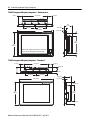
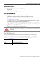
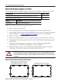
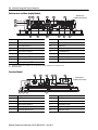
1
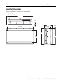
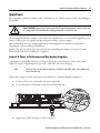
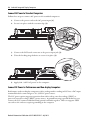
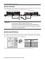
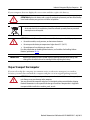
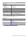
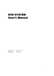
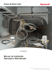
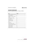
Installation Instructions
Industrial Integrated Display Computers
Catalog Numbers 6181F, 6181P
Topic
Page
Important User Information
2
Precautions
3
Computer Options
4
Operating Systems
5
Parts List
6
Mounting Clearances
8
Install the Computer
13
Mount the Display Computer in a Panel
14
Connect Peripherals
15
Connect Peripherals
15
Apply Power
17
Connect to a Network
20
Real Time Clock (RTC) Battery
20
Ship or Transport the Computer
21
Specifications
22
Additional Resources
24
2 Industrial Integrated Display Computers
Important User Information
Solid-state equipment has operational characteristics differing from those of electromechanical equipment. Safety Guidelines for
the Application, Installation and Maintenance of Solid State Controls (publication SGI-1.1 available from your local Rockwell
Automation sales office or online at http://www.rockwellautomation.com/literature/) describes some important differences
between solid-state equipment and hard-wired electromechanical devices. Because of this difference, and also because of the wide
variety of uses for solid-state equipment, all persons responsible for applying this equipment must satisfy themselves that each
intended application of this equipment is acceptable.
In no event will Rockwell Automation, Inc. be responsible or liable for indirect or consequential damages resulting from the use or
application of this equipment.
The examples and diagrams in this manual are included solely for illustrative purposes. Because of the many variables and
requirements associated with any particular installation, Rockwell Automation, Inc. cannot assume responsibility or liability for
actual use based on the examples and diagrams.
No patent liability is assumed by Rockwell Automation, Inc. with respect to use of information, circuits, equipment, or software
described in this manual.
Reproduction of the contents of this manual, in whole or in part, without written permission of Rockwell Automation, Inc., is
prohibited.
Throughout this manual, when necessary, we use notes to make you aware of safety considerations.
WARNING: Identifies information about practices or circumstances that can cause an explosion in a
hazardous environment, which may lead to personal injury or death, property damage, or economic loss.
ATTENTION: Identifies information about practices or circumstances that can lead to personal injury or
death, property damage, or economic loss. Attentions help you identify a hazard, avoid a hazard and
recognize the consequences.
SHOCK HAZARD: Labels may be on or inside the equipment, for example, a drive or motor, to alert people
that dangerous voltage may be present.
BURN HAZARD: Labels may be on or inside the equipment, for example, a drive or motor, to alert people
that surfaces may reach dangerous temperatures.
IMPORTANT
Identifies information that is critical for successful application and understanding of the product.
Rockwell Automation Publication 6181P-IN010F-EN-P - July 2013
Industrial Integrated Display Computers 3
Precautions
Read and follow these precautions for use.
Environment and Enclosure Information
ATTENTION: This equipment is intended for use in a Pollution Degree 2 industrial environment, in
overvoltage Category II applications (as defined in IEC publication 60664-1), at altitudes up to
2000 m (6561 ft) without derating.
This equipment is considered Group 1, Class A industrial equipment according to IEC/CISPR 11. Without
appropriate precautions, there may be difficulties with electromagnetic compatibility in residential and
other environments due to conducted and radiated disturbances.
UL listed equipment need not be mounted inside another enclosure if NEMA Type and IEC ratings
are not required, but the mounting method must limit the tilt of the computer to no more than 60°
from vertical. An example is a tabletop stand. The mounting means must be firmly attached to the
supporting surface using screws, bolts, or clamps so the computer cannot tip. These computers
ship with a gasketed bezel to meet specified NEMA and IEC ratings only when mounted in a panel
or enclosure with an equivalent rating. Subsequent sections of this publication may contain
additional information regarding specific enclosure type ratings that are required to comply with
certain product safety certifications.
In addition to this publication, see the following:
• Industrial Automation Wiring and Grounding Guidelines, publication 1770-4.1, for additional
installation requirements
• NEMA Standard 250 and IEC 60529, as applicable, for explanations of the degrees of protection
provided by enclosures
European Union Directive Compliance
This computer meets the European Union Directive requirements when installed within the
European Union or EEA regions and have the CE mark. A copy of the Declaration of
Conformity (DoC) is available at
http://www.rockwellautomation.com/rockwellautomation/certification/overview.page.
ATTENTION: This equipment is intended to operate in an industrial or control room environment,
which uses some form of power isolation from the public low-voltage mains. Some computer
configurations may not comply with the EN 61000-3-2 Harmonic Emissions standard as specified
by the EMC Directive of the European Union. Obtain permission from the local power authority
before connecting any computer configuration that draws more than 75 W of AC power directly
from the public mains.
To comply with EN 55024, the Ethernet port LAN cable must be less than 30 m (98.42 ft). All other
I/O cables must be less than 3 m (9.84 ft) and only used indoors; these cables must not exit the
building at any point.
Rockwell Automation Publication 6181P-IN010F-EN-P - July 2013
4 Industrial Integrated Display Computers
Computer Options
Available Options
Cat. No.
Model
Series
Display
Size (in.)
Storage(3)
Touchscreen
Windows OS
Package
6181F-2PW7
NDM
E
N/A
SSD
N/A
7 Pro 32 bit
Performance
6181F-2PW7DC(1)
6181P-2PW7
HDD
6181P-2PW7DC(1)
6181P-2PXP
XP Pro SP3
6181P-2PXPDC(1)
6181F-12TPW7
1200P
E
12.1
SSD
Yes
7 Pro 32 bit
Performance
6181F-12TPW7DC(1)
6181F-12TPWE
WES 2009
6181F-12TPWEDC(1)
6181F-12TPXP
XP Pro SP3
6181F-12TPXPDC(1)
6181F-12TSXP
Standard
6181F-12TSWE
WES 2009
6181P-12NSXP
HDD
No
XP Pro SP3
Yes
7 Pro 32 bit
6181P-12NPXP
Performance
6181P-12TPW7
6181P-12TPW7DC(1)
6181P-12TPXP
XP Pro SP3
6181P-12TPXPDC(1)
6181P-12TSXP
6181F-15TPW7
Standard
1500P
E
15
SSD
Yes
7 Pro 32 bit
Performance
6181F-15TPW7DC(1)
6181F-15TPW7SS(2)
6181F-15TPWE
WES 2009
6181F-15TPWEDC(1)
6181F-15TPWESS(2)
6181F-15TPXP
XP Pro SP3
6181F-15TPXPDC(1)
6181F-15TPXPSS(2)
6181F-15TSXP
Standard
6181F-15TSWE
6181P-15NSXP
WES 2009
HDD
No
XP Pro SP3
Yes
7 Pro 32 bit
6181P-15NPXP
6181P-15TPW7
6181P-15TPW7DC(1)
6181P-15TPW7SS(2)
Rockwell Automation Publication 6181P-IN010F-EN-P - July 2013
Performance
Industrial Integrated Display Computers 5
Available Options (cont.)
Cat. No.
Model
Series
Display
Size (in.)
Storage(3)
Touchscreen
Windows OS
Package
6181P-15TPXP
1500P
E
15
HDD
Yes
XP Pro SP3
Performance
1700P
E
17
SSD
Yes
7 Pro 32 bit
Performance
6181P-15TPXPDC(1)
6181P-15TPXPSS(2)
6181P-15TSXP
6181F-17TPW7
Standard
6181F-17TPW7DC(1)
6181F-17TPW7SS(2)
6181F-17TPWE
WES 2009
6181F-17TPWEDC(1)
6181F-17TPWESS(2)
6181F-17TPXP
XP Pro SP3
6181F-17TPXPSS(2)
6181F-17TPXPDC(1)
6181F-17TSXP
Standard
6181F-17TSWE
6181P-17NSXP
WES 2009
HDD
No
XP Pro SP3
Yes
7 Pro 32 bit
6181P-17NPXP
Performance
6181P-17TPW7
6181P-17TPW7DC(1)
6181P-17TPW7SS(2)
6181P-17TPXP
XP Pro SP3
6181P-17TPXPDC(1)
6181P-17TPXPSS(2)
6181P-17TSXP
Standard
(1) Models with a catalog number ending in DC operate from DC power.
(2) Models with a catalog number ending in SS have a stainless steel bezel.
(3) HDD signifies hard-disk drive and SSD signifies solid-state drive.
Operating Systems
Computers are shipped with one of these Microsoft-licensed operating systems:
• Windows 7 Professional (32 bit)
• Windows XP Professional, Service Pack 3
• Windows Embedded Standard (WES) 2009
No Windows XP operating system updates have been applied to the factory image beyond the
service packs. All available WES 2009 operating system updates have been applied as of
September 2009.
Rockwell Automation Publication 6181P-IN010F-EN-P - July 2013
6 Industrial Integrated Display Computers
For computers with the Windows XP operating system, the I386 source directory for Microsoft
Windows is on the system drive of your computer off the root directory, C:\I386. This allows for
easy removal and addition of Windows components.
Computers with rotating hard-disk drives include a recovery partition on the system drive
containing the original factory image. You can use the supplied Computer System Cloning CD
to restore the operating system from the recovery partition and create a new recovery image.
Refer to the Cloning Utility Technical Data, publication 6000-TD002, for instructions.
Computers with the WES 2009 operating system include a utility for configuring the Enhanced
Write Filter (EWF) and Hibernate Once, Restore Many (HORM) features. Refer to the
EWF/HORM Configuration Utility Technical Data, publication 6000-TD003, for instructions.
To obtain the original factory image on bootable external-recovery media, contact your local
technical support center.
Parts List
Your computer is shipped with the following items:
•
•
•
•
•
•
•
Panel mounting clips (display models only)
Power cord (for AC power models)
Ground bus strip, pre-installed (for DC power models)
Panel cutout template
Installation instructions
Production test report
System CDs
– Accessory CD with Cloning Utility (red)
– DVD burning software (Windows XP performance models only)
Rockwell Automation Publication 6181P-IN010F-EN-P - July 2013
Industrial Integrated Display Computers 7
Required Tools
These tools are required for computer installation:
• Panel cutout tools (panel mount only)
• #2 Phillips screwdriver
• Antistatic wrist strap (recommended)
Installation Guidelines
Follow these guidelines to make sure your computer provides safe and reliable service:
• The installation site must have sufficient power.
ATTENTION: To maintain an electrically safe installation, the AC powered computers must be plugged into a
grounded outlet.
• The enclosure must allow sufficient space around air inlets and outlets to provide the
circulation necessary for cooling. Never allow air passages to become obstructed.
• The ambient air temperature must not exceed the maximum operating temperature.
Consider heat produced by other devices in the enclosure. You can use a user-supplied
fan, heat exchanger, or air conditioner to meet this condition.
TIP
Hot air rises. The temperature at the top of the enclosure is often higher than the temperature
in other parts of the enclosure, especially if air is not circulating.
IMPORTANT
The computer can operate at a range of extremes. However, the life span of any electronic
device is shortened if you continuously operate the computer at its highest rated temperature.
• The humidity of the ambient air must not exceed specified limits. In very dry
environments, static charges build up readily. Proper grounding of the equipment helps
to reduce static discharges, which can cause shocks and damage electronic components.
• The enclosure or cover must remain in place at all times during operation. The cover
provides protection against high voltages inside the computer and inhibits
radio-frequency emissions that can interfere with other equipment.
Rockwell Automation Publication 6181P-IN010F-EN-P - July 2013
8 Industrial Integrated Display Computers
• When mounted, the computer cannot be tilted more than 60° from vertical.
≤60°
from Vertical
≤60°
from Vertical
Mounting Clearances
Because of self-heating, do not operate the computer in an enclosure using minimum
clearances unless adequate ventilation or other cooling methods are used to lower the
temperature within the enclosure.
IMPORTANT
1
2
3
5
4
Item
Description
Value
1
Top
50 mm (2 in.)
2
Left (for airflow)
50 mm (2 in.)
3
Back
50 mm (2 in.)
4
Right (for airflow and drive access)
127 mm (5 in.)
5
Bottom (for I/O port access and ventilation)
102 mm (4 in.)
Right and left are based on facing the front of the computer.
Rockwell Automation Publication 6181P-IN010F-EN-P - July 2013
Industrial Integrated Display Computers 9
Computer Dimensions
Dimensions for the computers are in mm (in).
Non-display Computers
353 (13.90)
1.6
(0.06)
108 (4.25)
335 (13.20)
83 (3.28)
12
(0.50)
238
(9.37)
190
(7.50)
251
(9.88)
Rockwell Automation Publication 6181P-IN010F-EN-P - July 2013
10 Industrial Integrated Display Computers
1200P Integrated Display Computer - Performance
320 (12.60)
115 (4.5)
115 (4.5)
124 (4.90)
99.8 (3.93)
14.5 (0.57)
349 (13.74)
279
(10.98)
250
(9.84)
1200P Integrated Display Computer - Standard
320 (12.60)
99.4 (3.91)
90.35 (3.56)
115 (4.5)
115 (4.5)
349 (13.74)
279
(10.98)
Rockwell Automation Publication 6181P-IN010F-EN-P - July 2013
85
(3.36)
14.5
(0.57)
251
(9.88)
Industrial Integrated Display Computers 11
1500P Integrated Display Computer - Performance
31.8 (1.25)
320 (12.60)
31.8 (1.25)
100
(3.94)
145 (5.7)
145 (5.7)
410 (16.14)
28 (1.10)
14.5 (0.57)
15.8 (0.62)
309
(12.16)
251
(9.88)
NOTE: 1500P computers with stainless steel bezels
do not have the front USB port shown at right.
15.8 (0.62)
1500P Integrated Display Computer - Standard
32.55 (1.28)
320 (12.6)
32.55 (1.28)
95
(3.74)
86 (3.38)
144 (5.67)
144 (5.67)
410 (16.14)
29 (1.1)
86
(3.38)
14.5
(0.57)
16.6 (0.7)
309
(12.17)
251
(9.88)
16.6 (0.7)
Rockwell Automation Publication 6181P-IN010F-EN-P - July 2013
12 Industrial Integrated Display Computers
1700P Integrated Display Computers - Performance
51 (2.0)
320 (12.56)
51 (2.0)
100
(3.94)
145 (5.7)
145 (5.7)
452 (17.80)
28 (1.10)
14.5 (0.57)
38 (1.51)
251
(9.89)
356
(14.01)
NOTE: 1700P computers with stainless steel bezels
do not have the front USB port shown at right.
38 (1.51)
1700P Integrated Display Computer - Standard
51 (2.0)
320 (12.6)
51 (2.0)
95 (3.74)
86 (3.38)
28.6 (1.13)
150 (5.90)
150 (5.90)
86 (3.38)
452 (17.80)
14.5 (0.57)
38.5 (1.51)
356
(14.02)
251
(9.88)
38.5 (1.51)
Rockwell Automation Publication 6181P-IN010F-EN-P - July 2013
Industrial Integrated Display Computers 13
Install the Computer
The computers support the following mounting options:
• Panel mount
• Wall mount (for non-display computers)
Panel Mounting Guidelines
Observe these guidelines when installing the computer in a panel:
• Remove all electrical power from the panel before making the cutout.
• Confirm that there is adequate space behind the panel. For specific information, refer to
Mounting Clearances on page 8.
• Cut supporting panels to specifications before installation. Take precautions so metal
cuttings do not enter components already installed in panel.
Supporting panels must be at least 14 gauge for proper sealing against water and dust,
and to provide proper support. The mounting hardware supplied accommodates panel
thickness 1.5…5.5 mm (0.06…0.25 in.).
• Make sure the area around the panel cutout is clear.
ATTENTION: Failure to follow these guidelines can result in personal injury or damage to the panel
components.
Panel Cutout Dimensions
The computers must be mounted to meet the panel cutout dimensions specified below.
Included with the computer is 6181P and 6181X Industrial Computers Cutout Template,
publication 6181P-DS002, with a cutout template for each display computer model.
Computer Model
Cutout Dimensions (H x W), approx
1200P
254.0 x 324.0 mm (10.0 x 12.76 in.)
1500P
285.0 x 386.6 mm (11.24 x 15.22 in.)
1700P
329.5 x 424.0 mm (12.97 x 16.69 in.)
Rockwell Automation Publication 6181P-IN010F-EN-P - July 2013
14 Industrial Integrated Display Computers
Mount the Display Computer in a Panel
Mounting clips secure the display computer to the panel. The number of clips varies by model.
Computer Model
Number of Clips
All display models with aluminum bezel and 1500P display with stainless steel bezel
10
1700P display with stainless steel bezel
12
Cat. No.
Description
6189V-MCLPS3
Replacement mounting clips (14)
Follow these steps to mount the computer in a panel.
1. Remove power from the panel.
2. Cut an opening in the panel by using the appropriate panel cutout dimensions.
3. Attach cables to the computer before installation if rear access to the computer is limited
after installation. See Connect Peripherals on page 15 for where to attach cables.
4. Place the computer in the panel cutout.
5. Slide the mounting clips into the holes on the top, bottom, and sides of the computer.
6. Hand-tighten the mounting clips around the bezel by following the tightening sequence
shown below.
7. Tighten the mounting clips to a torque of 1.35 N•m (12 lb•in) by following the
torquing sequence shown below, making sure to not overtighten.
8. Repeat the torque sequence at least three times until the clips are properly torqued,
making sure the gasket is compressed uniformly against the panel.
ATTENTION: Tighten the mounting clips to the specified torque to provide a proper seal and
prevent damage to the computer. Rockwell Automation assumes no responsibility for water or
chemical damage to the computer or other equipment within the enclosure because of improper
installation.
Mounting Clips Tightening and Torque Sequence
All Display Computers with Aluminum Bezel
and 1500P Display with Stainless Steel Bezel
9
1
1700P Display with Stainless Steel Bezel
10
5
9
3
4
6
8
2
1
10
5
3
11
12
4
6
7
Rockwell Automation Publication 6181P-IN010F-EN-P - July 2013
8
2
7
Industrial Integrated Display Computers 15
Mount the Non-display Computer on a Wall
Four mounting screws secure the non-display computers to a wall. Follow these steps to mount a
non-display computer.
1. Verify the power is
disconnected.
335 (13.20)
2. Mount the
computer to a wall
by using four M5
pan head screws
and tighten to a
torque that is
appropriate for the
screw and wall
material.
190 (7.50)
The illustration shows
hole locations with the
dimensions in mm (in.).
Connect Peripherals
Connect the required necessary peripherals such as keyboard and mouse.
Display computers with aluminum bezels have a front USB port for USB peripherals. This port
is enabled or disabled through settings in the BIOS set-up menu.
Item
Description
1
Front USB port access door
2
Front USB port, Type A
3
Access door lock
1
2
3
Rockwell Automation Publication 6181P-IN010F-EN-P - July 2013
16 Industrial Integrated Display Computers
Performance and Non-display Models
1
2
3
4
11
10
5
Bottom View
(1500P model shown)
6
15
14
13
12
9
8
7
Item
Component
Item
1
PS/2 mouse port
9
Component
Functional ground screw
2
PS/2 keyboard port
10
USB ports, 4
3
Parallel port
11
CompactFlash Type II card slot
4
Ethernet ports (RJ45), 2
12
Serial COM ports, 2
5
DVI-I port
13
Microphone-in jack
6
PCI riser slot cover(1)
14
Audio line-out jack
7
Power switch
15
Audio line-in jack
8
Power input, AC or DC(2)
(1)
(2)
1500P and 1700P have one PCI riser slot; 1200P and non-display computers have two PCI riser slots.
Model dependent.
Standard Model
1
2
3
4
5
6
Bottom View
(1500P model shown)
10
9
8
7
Item
Component
Item
Component
1
Power switch
6
Power input, AC
2
Serial COM port
7
USB ports, 4
3
Ethernet ports (RJ45), 2
8
Microphone-in jack
4
Power input, DC
9
Audio line-out jack
5
Functional ground screw
10
Audio line-in jack
Rockwell Automation Publication 6181P-IN010F-EN-P - July 2013
Industrial Integrated Display Computers 17
Apply Power
The computer connects to either a 100…240V AC or 18…32V DC power source, depending on
the model.
SHOCK HAZARD: Connect the AC power cord or the DC ground connection to a power source with
an earth ground. Failure to follow this warning could result in electrical shock.
We recommend that the computer circuit has its own disconnect. Use an uninterruptible power
source (UPS) to protect against unexpected power failure or power surges.
Always shut down the operating system before removing power to minimize performance
degradation and operating system failures.
Remove the AC retention clip, if necessary, before installing the computer in a panel cutout.
Reattach the clip after installing the computer.
Connect AC Power to Performance and Non-display Computers
A grounded 3-prong IEC320 power cord provides power to a computer with an AC power
input. The power supply input accepts 100…240V AC and is autoranging.
TIP
If using an alternate IEC320 cord, make sure the female end of the cord is sized appropriately
for the retention clip.
Follow these steps to connect AC power to performance and non-display computers.
1. Connect the power cord to the AC power input (1).
2. Secure the power cord in place with the retention clip (2).
2
1
3. Apply 100…240V AC power to the computer.
Rockwell Automation Publication 6181P-IN010F-EN-P - July 2013
18 Industrial Integrated Display Computers
Connect AC Power to Standard Computers
Follow these steps to connect AC power to the standard computers.
1. Connect the power cord to the AC power input (1).
2. Secure it in place with the retention clip (2).
1
2
3. Connect the DC barrel connector to the power input jack (3).
4. Twist the locking ring clockwise to secure it in place (4).
4
3
5. Apply 100…240V AC power to the computer.
Connect DC Power to Performance and Non-display Computers
Performance and non-display computers with a catalog number ending in DC have a DC input
terminal block for connecting to a 18…32V DC power source.
The DC power option supports operation from either safety extra-low voltage (SELV) or
protected extra-low voltage (PELV) power source. A ground bus strip is provided that lets you
connect the DC common and functional ground terminals together. This is to support SELV
cases where the end user requires grounding at the computer.
Rockwell Automation Publication 6181P-IN010F-EN-P - July 2013
Industrial Integrated Display Computers 19
The power supply is internally protected against reverse polarity.
ATTENTION: Use a SELV isolated and ungrounded power supply as input power to the computer.
This power source provides protection so that under normal and single fault conditions, the
voltage between the conductors and functional earth/protective earth does not exceed a safe
value.
Follow these steps to connect the computer to a DC power source.
1. Verify the main power switch or breaker is off.
2. Verify that the DC power wires meet these requirements:
• Material: Stranded copper
• Wire gauge: 0.325…0.823 mm2 (22…18 AWG)
3. Secure the DC power wires to the terminal block screws, and the ground wire to the
GND terminal screw.
Tighten the terminal to a torque of 0.687 N•m (6.1 lb•in).
4. Apply 18…32V DC power to the computer.
Non-display Computer Shown
+v -v
GND
Pre-installed DC
Ground Bus Strip
Functional Ground Screw
The pre-installed functional ground screw is
not required for safety or regulatory
compliance. However, if a supplemental
ground is desired, use the functional ground
screw in the I/O port panel of the computer.
If using the functional ground screw, connect
the computer to earth ground by using
a 1.5 mm (16 AWG) or larger external wire.
Use a ground wire with green insulation and a
yellow stripe for easy identification.
Non-display Computer
Standard Computer
Performance Computer
Rockwell Automation Publication 6181P-IN010F-EN-P - July 2013
20 Industrial Integrated Display Computers
Connect to a Network
The computers have 2 Gb LAN ports. The computers connect to an Ethernet network by using
CAT5 or CAT5E twisted-pair Ethernet cabling with RJ45 connectors.
Performance and Non-display Computer
IMPORTANT
Standard Computer
To prevent performance degradation of Ethernet communication, do not subject the computer
or cables to extreme radiation or conducted high-frequency noise.
Proper cable routing and power conditioning is required to be sure of reliable Ethernet
communication in an industrial environment. Rockwell Automation recommends that you
route all Ethernet cabling through dedicated metal conduits. Installing ferrite bead filters at
the cable ends can also improve reliability.
Real Time Clock (RTC) Battery
This computer contains a lithium battery that must be replaced during the life of the computer.
The computers use nonvolatile memory that require a battery to retain system information when
power is removed. The battery is beside the DIMM1 slot.
On-time
(hrs/wk)
Expected Battery
Life (yrs)
0
4
40
5.5
80
7
The battery life depends on the amount of time the computer is powered on.
Rockwell Automation Publication 6181P-IN010F-EN-P - July 2013
Industrial Integrated Display Computers 21
If your computer does not display the correct time and date, replace the battery.
ATTENTION: Replace the battery with a specially-packaged replacement part from Allen-Bradley.
Use of another battery may present a risk of fire or explosion.
At the end of its life, the used battery should be collected separately from any unsorted
municipal waste and recycled.
ATTENTION: A risk of fire and chemical burn exists if the battery is not handled properly:
• Do not disassemble, crush, puncture, or short external contacts.
• Do not expose the battery to temperatures higher than 85 °C (185 °F).
• Do not dispose of a used battery in water or fire.
For safety information on handling lithium batteries, see Guidelines for Handling Lithium
Batteries, publication AG-5.4.
IMPORTANT
Replacing the battery results in all BIOS settings returning to their default settings. BIOS
settings other than default must be reconfigured after replacing the battery.
Ship or Transport the Computer
If you need to ship the computer via common carrier or otherwise transport it to another
location, you must first uninstall the computer and place it in its original packing material.
ATTENTION: Do not ship or transport the computer when it is installed in a machine, panel, or
rack. Doing so can cause damage to the computer.
You must uninstall the computer and place it in its original packing material before shipping.
Rockwell Automation is not responsible for damage incurred to a computer that is shipped or
transported while installed in a machine, panel, or rack.
Rockwell Automation Publication 6181P-IN010F-EN-P - July 2013
22 Industrial Integrated Display Computers
Specifications
Refer to the Industrial Integrated Display Computers User Manual, publication 6181P-UM002,
for additional specifications.
Electrical
Attribute
6181F, 6181P
Performance and non-display, AC
Input voltage, AC
Line frequency
Power consumption, AC
100…240V AC, autoranging
47…63 Hz
110VA (0.95 A @ 100V rms, 0.46 A @ 240V rms)
Performance and non-display, DC
Input voltage, DC
Power consumption, DC
18…32V DC
95 W (5.28 A @ 18V, 2.97 A @ 32V)
Standard models
Input voltage, AC
Line frequency
Input voltage, DC(1)
Power consumption, AC
100…240 V AC, autoranging
47…63 Hz
20V DC (3.25 A)
100VA (1 A @ 100V rms, 0.42 A @ 240V rms)
Heat dissipation(2)
65 W (222 BTU/hr)
(1)
(2)
Power adapter required.
Add-in cards and peripherals are not included in the heat dissipation value. Calculate heat dissipation separately for installed add-in cards and
peripherals.
Mechanical
Attribute
6181F, 6181P
Weight, approx
Non-display
1200P Performance
1200P Standard
1500P Performance
1500P Performance w/stainless steel bezel
1500P Standard
1700P Performance
1700P Performance w/stainless steel bezel
1700P Standard
7.7 kg (16.98 lb)
9.5 kg (20.94 lb)
7.85 kg (17.31 lb)
10.7 kg (23.59 lb)
11.9 kg (26.24 lb)
9.0 kg (19.84 lb)
12.6 kg (27.78 lb)
14.5 kg (31.97 lb)
11.0 kg (24.25 lb)
Dimensions, overall (HxWxD, approx)
Non-display
1200P Performance
1200P Standard
1500P Performance
1500P Standard
1700P Performance
1700P Standard
251 x 353 x 108 mm (7.5 x 13.20 x 4.25 in.)
279 x 349 x 124 mm (10.98 x 13.74 x 4.90 in.)
279 x 349 x 99 mm (10.98 x 13.74 x 3.91 in.)
309 x 410 x 100 mm (12.16 x 16.14 x 3.94 in.)
309 x 410 x 95 mm (12.16 x 16.14 x 3.74 in.)
356 x 452 x 100 mm (14.01 x 17.80 x 3.94 in.)
356 x 452 x 95 mm (14.01 x 17.80 x 3.74 in.)
Enclosure ratings (for display models only)(1)
Performance
Performance w/stainless steel bezel
Standard
NEMA Type 1, 12, 4, and IEC IP66
NEMA Type 1, 12, 4, 4X, and IEC IP66
NEMA Type 1, 12, 4, and IEC IP66
(1)
Type ratings apply only when computer is properly mounted on a flat surface of an equivalent type enclosure.
Rockwell Automation Publication 6181P-IN010F-EN-P - July 2013
Industrial Integrated Display Computers 23
Environmental
Attribute
6181F, 6181P
Temperature, operating(1)
All Standard models
Non-display
1200P and 1500P Performance
1700P Performance
0…50 °C (32…122 °F)
0…55 °C (32…131 °F)
0…55 °C (32…131 °F)
0…50 °C (32…122 °F)
Temperature, nonoperating(1)
-20…60 °C (-4…140 °F)
Relative humidity
10…90% noncondensing
Altitude, operating
2000 m (6561 ft)
Altitude, nonoperating
12,000 m (40,000 ft)
Shock, operating(1)(2)
15 g (1/2 sine, 11 ms)
Shock, nonoperating(1)(2)
30 g (1/2 sine, 11 ms)
Vibration, operating(1)(2)
6181F
6181P
0.012 in. p-p, (10…57 Hz); 2 g peak, (57…640 Hz)
0.006 in. p-p, (10…57 Hz); 1 g peak, (57…640 Hz)
Vibration, nonoperating(1)(2)
0.012 in. p-p, (10…57 Hz); 2 g peak, (57…640 Hz)
(1)
The optical disc drive (ODD) is considered a maintenance device. Therefore, do not operate computers with ODDs in temperatures above 45 °C
(113 °F) or in environments with the shock and vibration levels listed.
Applies only to panel mounted display computers and wall mounted non-display computers.
(2)
Certifications (1)
Attribute
6181F, 6181P
c-UL-us
UL/c-UL Listed per UL 60950-1 and CSA C22.2 No. 60950-1-03
CE
Marked for all applicable directives
EMC 2004/108/EC
LVD 2006/95/EC
C-Tick
Australian Radiocommunications Act, compliant with:
AS/NZS CISPR 11; Industrial Emissions
RoHS
China RoHS
Turkey RoHS (EEE Yönetmeliğine Uygundur. In Conformity with the EEE Regulation)
(1)
See http://www.rockwellautomation.com/rockwellautomation/certification/overview.page for declarations of conformity, certificates, and other
certification details.
Rockwell Automation Publication 6181P-IN010F-EN-P - July 2013
Additional Resources
These documents contain additional information about related products from Rockwell Automation.
Resource
Description
Industrial Integrated Display Computer
User Manual, publication 6181P-UM002
Provides a system overview and procedures to install the computer, set up computer
connections, operate the computer, and troubleshoot the computer.
Cloning Utility Technical Data, publication
6000-TD002
Provides information on how to create and restore a back-up image of your
computer’s hard drive.
Diagnostic Utility for Industrial Computers,
publication 6000-TG001
Provides information on how to diagnose hardware issues with industrial computers.
EWF and HORM Configuration Utility
Technical Data, publication 6000-TD003
Provides information on how to configure Enhanced Write Filter (EFW) and
Hibernate Once Restore Many (HORM) features for computers with the Windows
Embedded Standard 2009 operating system.
You can view or download publications at http://www.rockwellautomation.com/literature. To
order paper copies of technical documentation, contact your local Allen-Bradley distributor or
Rockwell Automation sales representative.
Allen-Bradley, Rockwell Software, and Rockwell Automation are trademarks of Rockwell Automation, Inc.
Trademarks not belonging to Rockwell Automation are property of their respective companies.
Rockwell Otomasyon Ticaret A.Ş., Kar Plaza İş Merkezi E Blok Kat:6 34752 İçerenköy, İstanbul, Tel: +90 (216) 5698400
Publication 6181P-IN010F-EN-P - July 2013
Supersedes Publication 6181P-IN010E-EN-P - September 2012
PN-30419
DIR 10000039347 (Version 02)
Copyright © 2013 Rockwell Automation, Inc. All rights reserved. Printed in China.