1
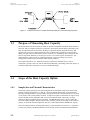
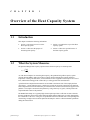
C
H
A
P
T
E
R
1
Overview of the Heat Capacity System
1.1
Introduction
This chapter contains the following information:
1.2
•
Section 1.2 presents an overview of the
Heat Capacity option.
•
Section 1.4 explains the scope of the Heat
Capacity option.
•
Section 1.3 discusses the purpose of
measuring heat capacity.
•
Section 1.5 discusses special features of
the Heat Capacity option.
What the System Measures
The Quantum Design Heat Capacity option measures the heat capacity at constant pressure
⎛ dQ ⎞
Cp = ⎜
⎟ .
⎝ dT ⎠ p
As with other techniques for measuring heat capacity, the Quantum Design Heat Capacity option
controls the heat added to and removed from a sample while monitoring the resulting change in
temperature. During a measurement, a known amount of heat is applied at constant power for a fixed
time, and then this heating period is followed by a cooling period of the same duration.
A platform heater and platform thermometer are attached to the bottom side of the sample platform.
(See Figure 1-1 on the following page). Small wires provide the electrical connection to the platform
heater and platform thermometer and also provide the thermal connection and structural support for the
platform. The sample is mounted to the platform by using a thin layer of grease, which provides the
required thermal contact to the platform.
The PPMS Turbo Pump or Cryopump High-Vacuum option provides a sufficient vacuum so that the
thermal conductance between the sample platform and the thermal bath (puck) is totally dominated by
the conductance of the wires. This gives a reproducible heat link to the bath with a corresponding time
constant large enough to allow both the platform and sample to achieve sufficient thermal equilibrium
during the measurement.
Quantum Design
PPMS Heat Capacity Option User’s Manual
1-1
Section 1.4
Scope of the Heat Capacity Option
Chapter 1
Overview of the Heat Capacity System
Figure 1-1. Thermal Connections to Sample and Sample Platform in PPMS Heat Capacity Option
1.3
Purpose of Measuring Heat Capacity
The measurement of the heat capacity of solids can provide considerable information about the lattice,
electronic, and even magnetic properties of materials. Heat capacity measurements, particularly when
taken at temperatures that are well below the Debye temperature, directly probe the electronic and
magnetic energy levels of a material and hence allow comparisons between theory and experiment.
While electronic transport measurements, such as resistivity, are substantially more common, the link
between experiment and theory is not always as clear as it is in a heat capacity measurement. Any
statistical theory of matter involves computing the density of states and energy levels; these
computations naturally lead to predictions of heat capacity numbers.
From a practical point of view, materials used in the construction of thermal devices, such as
refrigerators, cryostats, and so on, must be characterized thermally. Knowledge of the heat capacity of
construction materials is important to any successful thermal design.
1.4
Scope of the Heat Capacity Option
1.4.1
Sample Size and Thermal Characteristics
In the Heat Capacity option, the basic puck configuration accommodates small, but not microscopic,
samples weighing approximately 1 to 200 mg. Given the thermal characteristics of the calorimeter,
this range of masses produces, for most solids, varying relaxation time constants that may be a fraction
of a second at 1.9 K or many minutes at 300 K. A single heat capacity measurement can require nearly
10 time constants for the settling time that occurs between measurements. Measuring very large
samples can thus be prohibitively time consuming. The addenda heat capacity, however, limits the
size of the smallest samples. Measurement accuracy, which is generally a percentage of the total heat
capacity, is sacrificed when the sample heat capacity is small compared to the addenda heat capacity.
Since the technique used for measuring heat capacity, as described below in Section 1.4.3, is dynamic
in nature, the geometry and thermal diffusivity of the sample must be such that the thermal diffusion
1-2
PPMS Heat Capacity Option User’s Manual
Quantum Design
Chapter 1
Overview of the Heat Capacity System
Section 1.4
Scope of the Heat Capacity Option
time in the sample is small compared to the time constant of the measurement. In cases where the
amount of time it takes for the sample to reach internal thermal equilibrium is not small compared to
the measurement time, the resulting heat capacity measurement will be too small. Although this
problem is indicated in the software as a poor thermal contact between the sample and the sample
holder, it is important to use samples that have relatively fast thermalization times to get the correct
heat capacity numbers. In cases where the thermal diffusion time in the sample is large, it is necessary
to use samples that have a relatively flat geometry, so as to reduce the thermal path through the sample.
1.4.2
Temperature Range
The Heat Capacity option has no fundamental temperature range limit other than the PPMS
temperature range. However, relaxation techniques are traditionally used at temperatures that are
below approximately 100 K, because relaxation times are relatively short below 100 K. The Heat
Capacity option can measure heat capacity up to about 400 K.
The percent resolution of the thermometry is relatively constant over the temperature range. Hence, at
higher temperatures, the absolute temperature resolution is somewhat poorer.
1.4.3
Measurement Technique
Many different measurement techniques (Stewart 1983) are optimized for different sample sizes and
accuracy requirements (high resolution versus accuracy). The Quantum Design Heat Capacity option
uses a relaxation technique that combines the best measurement accuracy with robust analysis
techniques. After each measurement cycle⎯which is a heating period followed by a cooling period⎯
the Heat Capacity option fits the entire temperature response of the sample platform to a model that
accounts for both the thermal relaxation of the sample platform to the bath temperature and the
relaxation between the sample platform and the sample itself (Hwang, Lin, and Tien 1997). The effect
of the relaxation between the platform and sample must be considered when the thermal connection
shared by the sample and platform is poor. By modeling this effect, the software can report the correct
heat capacity values despite such poor contact.
1.4.4
Pressure in Sample Chamber
The wires connecting the sample platform to the puck frame create well-controlled thermal links to the
thermal bath. To eliminate alternate thermal links through residual gas, the pressure within the probe
must be less than approximately 1 mTorr. The PPMS High-Vacuum option, which operates in
conjunction with the Heat Capacity option, maintains this low pressure. A charcoal holder is used as a
cryopump to help decrease the pressure at the bottom of the probe at temperatures below 10 K. When
the High-Vacuum option is activated, base pressures of approximately 0.01 mTorr are typical at the top
of the probe.
Quantum Design
PPMS Heat Capacity Option User’s Manual
1-3
Section 1.5
Special Features of the Heat Capacity Option
Chapter 1
Overview of the Heat Capacity System
1.5
Special Features of the Heat Capacity Option
1.5.1
Acquisition Hardware
Relaxation techniques require accurate time-resolution of the temperature response of the sample
platform during the measurement cycle as well as precise correlation of the heater output and the
temperature response. Fast, accurate thermometry is essential for the best signal-to-noise ratio. These
requirements for relaxation calorimetry place considerable demands on the data acquisition portion of a
system. Rather than attempt to adapt existing data acquisition hardware to the task, Quantum Design has
developed a high-performance controller optimized for relaxation calorimetry.
1.5.2
Calorimeter Puck and Sample Mounting
As with standard PPMS units, the calorimeter is a puck that you insert into the sample chamber. The
Heat Capacity option includes more than one puck, so you can prepare a second sample on the second
puck while the first puck is in the sample chamber. When you have measured the first sample, you may
immediately insert the second puck and measure the second sample without having to remove the
sample from the first puck.
You use a sample-mounting station to hold the puck when you mount and remove samples. The station
uses a puck interlock arm and vacuum suction to stabilize the puck and the sample platform. By
stabilizing the sample platform, the station helps protect the delicate, thermally conducting wires that
connect the platform to the puck frame.
1.5.3
Puck Calibration
The Heat Capacity software includes a fully automatic thermometer calibration routine that uses the
PPMS system thermometer as the reference thermometer to produce temperature calibrations for the
puck thermometer, platform thermometer, and platform heater. The calibration routine thus reduces the
cost of the pucks, because the pucks do not require factory calibration. Moreover, the calibration routine
allows you to design custom pucks that have different characteristics but that can still work with the
Heat Capacity option if you use the standard calibration procedure to calibrate the pucks.
1.5.4
Automation Environment
You may program the Heat Capacity option, just as you may program other PPMS measurement options,
to automatically acquire data. You use sequences, which are the PPMS automation language, to run any
number of measurement macros. You may also run each macro independently.
Sophisticated data analysis, which is part of the Heat Capacity option, is critical to your ability to run
heat capacity measurements while you are away from the system. Monitoring each measurement and its
associated fit in order to detect potential problems is unnecessary. The Heat Capacity software writes all
relevant diagnostic information and the heat capacity numbers to an open data file. When the
measurement is complete, you examine this data file. Errors are automatically computed for each
sample heat capacity measurement.
1-4
PPMS Heat Capacity Option User’s Manual
Quantum Design