1
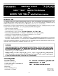
Thermoplastic Battery Unit
Emergency Lighting
IMPORTANT SAFEGUARDS
Emergency Lighting
When using electrical equipment, basic safety precautions should always be
followed including the following:
READ AND FOLLOW ALL SAFETY
INSTRUCTIONS
1.
2.
3.
4.
Do not let power supply cords touch hot surfaces.
Do not mount near gas or electric heaters.
Use caution when handling batteries. Avoid possible shorting.
Battery latch
placement
Equipment should be mounted in locations and at heights where it will not
readily be subjected to tampering by unauthorized personnel.
5. The use of accessory equipment not recommended by the manufacturer may
cause an unsafe condition.
6. Caution: If optional Halogen cycle lamp(s), symbol (H—), are used in this
equipment, to avoid shattering: do not operate lamp in excess of rated
voltage, protect lamp against abrasion and scratches and against liquids
when lamp is operating, dispose of lamp with care.
7. Halogen cycle lamps operate at high temperatures. Do not store or place
flammable materials near lamp.
8. Do not use this equipment for other than intended use.
9. All servicing should be performed by qualified service personnel.
Caution! For models including battery support plate (3) it is critical
to ensure that the hooked end of the bracket is properly latched to
the battery support plate (see Fig. 1). Failure to do so can cause a
serious injury.
Caution! Velcro straps are a temporary means to support the
batteries. You must always reinstall the battery retaining
bracket(11).
SAVE THESE INSTRUCTIONS
20W lamp
assembly
option
Figure 1
Part List
1. Front cover
9. Junction box
2. Charger board
10. Junction box screw 8-32 x
1-1/2”
3. Battery Support plate (only
for certain models)
11. Battery retaining bracket
4. Transformer
12. Velcro strap
5. Battery (1 or 2 depending
on models)
13. Heat shield (20W units
only)
6. Housing
7. Lamp assembly
14. Wall mounting screws ( not
provided)
8. Lens
15. Bracket locking screw
Installation Instructions
1. Turn off unswitched AC power.
2. Route AC unswitched circuit of rated voltage into electrical box and leave 6" of
wire length.
3. Lay unit on a flat surface face up. Remove lenses (8) and heat shields (13)
(for units with 20W lamps) (See Fig. 1) and leave lamps detached from the
housing.
4. Remove the front cover (1).
5. Remove the battery support bracket (11) (See Fig.2) and battery(ies) and note
how they are connected to reproduce this upon re-assembly.
6. Determine the mounting position (wall or ceiling).
1. Knock-out the proper hole pattern in the housing (6) to mount to a standard
junction box (9) (See Fig. 2) according to the required orientation. To do so, it
is recommended to place the unit on a flat solid surface with the back of the
housing facing the surface. Prop up the unit on a roll of tape or other solid
means to facilitate the removal of the knock-outs. Place the tip of a flat head
screwdriver in the groove and knock out each detail with the help of a hammer
(See Fig. 2).
2. Remove bubble wrap and install lamp assemby (7) (See Fig. 1).
3. Install means to anchor unit in line with "Wall anchoring points" (see Fig. 2).
This is recommended for a more secure installation.
4. Install junction box screws until they protrude 1" minimum from the wall.
5. Feed the AC supply leads and wires from remotes (if applicable).
Tel: (888) 552-6467
Fax: (800) 316-4515
Wall Anchoring Points
Junction
Box
Anchoring
Points
Center
Hole
Knock-out
groove
Wall Mounting
Technical Information
Flat head
screw driver
Flexible Conduit
Flat ceiling mount
*
Wall mount
Figure 2
*Shape of bracket and means to install them varies.
Refer to web site on unit label inside unit
03/11 750.1407 Rev. B
1/2
Thermoplastic Battery Unit
6. Mount housing to the junction box.
7. Make the proper connections: our system can accept input voltages of 120
VAC or 347 VAC. Therefore, connect the black (120 VAC) or red (347 VAC)
and white (common) leads to the building utility. Connect the green wire to the
ground.
Unused primary wire must be insulated to prevent shorting.
8.
9.
10.
11.
12.
13.
14.
15.
Route entry wires to avoid contact with the transformer, battery terminals
and charger PCBA. Refer to figure 3.
Secure the housing to the wall at wall anchoring points using wall mount
screws (14), then to the junction box using the junction box screws (10).
Connect the tips of each Velcro strap to form the largest possible loop.
Reinstall the battery(ies) by connecting the wires first before securing each
battery in the housing. Secure the Velcro strap(s) and battery bracket with
locking screw (15) when supplied. Connect the battery to the charger board.
For units with remote capacity, connect the remote heads to L+ and to L-.
Calculation of total allowable remote capacity of unit:
Maximum remote lamp power = unit capacity minus the total power of
lamps included with unit.
Adjust the lamps in an appropriate position.
Put the unit cover back in place.
Install the heat shields (units with 20W lamps only) and lenses.
Energize AC.
Emergency Lighting
*Flexible conduit or Pendant mount wire configuration
Incoming line
Charger
PCBA
Transformer
Optional area to
make connections
for a safer
installation with
one battery.
L+
L-
Wiring to
be done in
this area.
Transformer wires
347 VAC Red
120 VAC Black
White Neutral
Ground
Housing
Caution:
Route entry wires to avoid contact with the
transformer, battery terminals and charger PCBA.
*Wall or ceiling mount wire configuration
Charger
PCBA
Wiring to
be done in
this area.
Transformer
Optional area to
make connections
for a safer
installation with
one battery.
L+
L-
Transformer wires
347 VAC Red
120 VAC Black
White Neutral
Ground
Flat Ceiling Mounting (optional)
Follow same steps as outlined for Wall Mounting. No canopy is required.(See
Fig.2.)
Caution! DO NOT install unit to the ceiling unless its model number
includes the suffix " -CM "
Pendant Mounting
Housing
*Wire configuration with battery(ies) installated
Charger
Refer to Addendum for Pendant Mounting.
L+
L-
Transformer
PCBA
Conduit Entry Connection (Flexible conduit only)
Remove knock-out for the conduit entry located on the top of the housing (See
Fig. 2).
Secure unit to the wall following "Wall mounting" or "Ceiling mounting" instructions
and make appropriate connections. Isolate wires from building to avoid contact
with the transformer.
Wiring to
be done in
this area.
Battery
Wall mount
unit shown
Battery
Housing
Figure 3
*Unused primary wire must be insulated to prevent shorting.
Manual Testing
AC/Status
Press test switch. On release, external green LED will illuminate and automatic
charger will restore battery to full charge.
AC
Automatic Testing
Test
The unit will perform an automatic self-test of 1 minute every month,
10 minutes every 6 month and a 30 minutes self-test once a year.
Test switch
JP5
Automatic Diagnostics
The diagnostic function uses an external LED Status indicator. Service is required
if the LED blinks indicating that an alarm condition is detected (See Fig. 4). For
more information refer to the website address indicated on the unit label located
inside the unit. For more information about the AD function, please consult the
web site for this user manual:
“AD with Single LED Status User Manual”
For Nexus models, refer to “Nexus addendum” and for any additional information,
go to www.Nexus-System.com.
If you wish to make the unit “audible” or “non-audible” simply re-orient the jumper
“JP5” as shown in figure 4.
Maintenance
None required. If AC supply to the unit is to be disconnected for 2 months or more,
the battery must be disconnected.
Note — Nickel Cadmium battery units are shipped discharged and may require 10
minutes of connection to AC supply before start-up test procedure, and 96 hours
to reach full charge or 24 hours to charge to meet a 30 minute discharge.
Technical Information
Tel: (888) 552-6467
Fax: (800) 316-4515
audible
non-audible
Test switch
o
Green
-o
Green
o
Red
-o
Red
o-o
Red
o-o-o
Red
Steady
AC On
Blinking
In Test
Steady on
Battery Disconnect
Blinking
Battery Failure
Two Blinks
Charger failure
Three Blinks
Lamp Failure
Figure 4
Refer to web site on unit label inside unit
03/11 750.1407 Rev. B
2/2

![588-589-00a [Converted]](http://vs1.manualzilla.com/store/data/005638396_1-02d08bb06dde3fa2099be559e669b8e9-150x150.png)