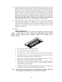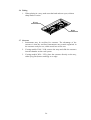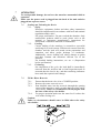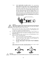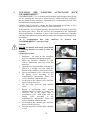
1
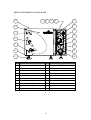
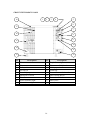
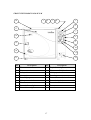
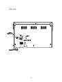
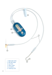
OPERATION & MAINTENANCE MANUAL Tabletop Autoclaves Models 1730, 2340, 2540, 3140, 3850, 3870 M & MK 1730MK Valueklave Cat. No. MAN205-0007000EN Rev. Q Tuttnauer U.S.A. Co, Ltd. 25 Power Drive Hauppauge, NY, 11788, USA. Tel (631) 737 4850, (800) 624 5836, Fax: (631) 737 0720 TABLE OF CONTENTS PARAGRAPH 1 2 3 4 5 6 7 8 9 10 11 PAGE NO. GENERAL................................................................................................................3 1.1 Incoming Inspection .....................................................................................3 1.2 Warranty........................................................................................................3 1.3 Warranty Statement ......................................................................................3 TECHNICAL DATA ................................................................................................5 2.1 Introduction ..................................................................................................5 2.2 Storage Conditions ........................................................................................6 2.3 Operating Conditions ....................................................................................6 2.4 Standards.......................................................................................................6 2.5 Construction..................................................................................................6 2.6 Utilities ..........................................................................................................7 2.7 Waste Water Disposal ...................................................................................7 2.8 Environment Emission Information.............................................................7 2.9 Dimensions, Models 1730 .............................................................................8 2.10 Dimensions, Models 2340, 2540 ...................................................................9 2.11 Dimensions, Models 3140 ...........................................................................10 2.12 Dimensions, Models 3850, 3870 .................................................................11 2.13 Technical Specifications .............................................................................12 2.14 Electrical Data ............................................................................................13 2.15 Maximum Solid Load Sizes.........................................................................13 2.16 Symbol Description .....................................................................................13 DESCRIPTION OF COMPONENTS....................................................................19 3.1 Control Panel ..............................................................................................19 3.2 Other Components ......................................................................................19 INSTALLATION INSTRUCTIONS ......................................................................20 4.1 Electrical .....................................................................................................20 4.2 Setup............................................................................................................20 4.3 Lifting and Carrying ...................................................................................21 WATER QUALITY ................................................................................................22 PREPARATION BEFORE STERILIZATION .....................................................23 OPERATION .........................................................................................................27 7.1 Loading and Unloading the Device ............................................................27 7.2 Fill the Water Reservoir..............................................................................27 SERVICE AND MAINTENANCE INSTRUCTIONS...........................................32 8.1 Preventive and Scheduled Maintenance.....................................................32 8.2 Draining the Reservoir................................................................................33 8.3 Cleaning the Air Jet ....................................................................................34 8.4 Replacing the Door Gasket .........................................................................35 8.5 Checking the Safety Valve ..........................................................................36 8.6 Unclogging the Multi-Purpose Valve or Fill Piping. .................................37 CLEANING THE TABLETOP AUTOCLAVES WITH CHAMBER BRITE™...38 TROUBLESHOOTING .........................................................................................40 LIST OF ACCESSORIES......................................................................................50 1 TABLE OF CONTENTS (Cont.) DRAWINGS PAGE NO. Front View Model 1730 M, MK-Valueklave.................................................................. 14 Front View Model 2340/2540 M, MK ............................................................................ 15 Front View Model 3140 M.............................................................................................. 16 Front View Model 3850/3870 M..................................................................................... 17 Rear View ........................................................................................................................ 18 Tray Handle CT530020 .................................................................................................. 48 Pouch Rack ..................................................................................................................... 48 Tray .................................................................................................................................. 48 Tray Holder ..................................................................................................................... 49 2 1 GENERAL Read the Operating Instructions carefully, before beginning any operation on the autoclave! 1.1 Incoming Inspection Upon receiving your Tuttnauer Autoclave carefully inspect the outside of the shipping carton for signs of damage. If any damage to the carton is found, note the location with respect to the autoclave and check that area of the autoclave carefully once it is fully unpacked. Observe packing method and retain packing materials until the unit has been inspected. Mechanical inspection involves checking for signs of physical damage such as: scratched panel surfaces, broken knobs, etc. If any damage is found, contact your dealer as soon as possible so that they can file a claim with the shipping carrier and also notify Tuttnauer. All Tuttnauer products are carefully inspected prior to shipment and all reasonable precautions are taken in preparing them for shipment to assure safe arrival at their destination. Note: Lifting and carrying should always be done by two people. 1.2 Warranty We certify that this instrument is guaranteed to be free from defects in material and workmanship for one year against faulty components and assembly. This warranty does not include routine cleaning and preventive maintenance to be performed according to instructions in section 8.1 (Preventive and Scheduled Maintenance). Tuttnauer warrantees all new Manual autoclaves for a period of one full year, covering both parts and labor. This one year warranty covers defects in materials and workmanship on every part in the autoclave except door gaskets and HEPA filters (they are wear items). Tuttnauer warrantees all chambers for a period of ten (10) years against defects in materials and workmanship. This chamber warranty went into effect January 1997. This warranty does not apply to any instrument that has been subjected to misuse, neglect, accident or improper installation or application, nor shall it extend to autoclaves that have been repaired or altered outside the factory without prior authorization from Tuttnauer. Tuttnauer’s obligation is limited to the repair or replacement of parts for the autoclave. This warranty will be void if the unit is not purchased from an authorized Tuttnauer dealer. No other warranties or obligations are expressed or implied. The Autoclave should only be used in a manner described in this manual! 1.3 Warranty Statement To activate the warranty, the registration card must be completed and returned to Tuttnauer within fourteen (14) days of purchase or you may call our customer service department at the number listed below. No product will be received or accepted for repair without prior return authorization from Tuttnauer. All transportation charges to and from Tuttnauer must be paid by the owner of the autoclave. During the first 3 90 days after purchase of an autoclave, Tuttnauer will pay shipping costs on an individually evaluated basis and ONLY with pre-approval. Note: If you have any questions or there are any difficulties with this instrument and the solution is not covered in this manual, please contact your dealer or our Technical Service Dept. at the address below. Do not attempt to service this instrument yourself. Tuttnauer USA Co., Ltd. 25 Power Drive Hauppauge, NY, 11788, USA : (800) 624 5836, (631) 737 4850, Fax: (631) 737 0720 e-mail:[email protected] 4 2 TECHNICAL DATA 2.1 Introduction This tabletop autoclave is designed for the sterilization of wrapped and unwrapped instruments and related items found in dental, medical and veterinary clinics, first aid rooms, laboratories, etc. This autoclave is an electrically heated sterilizer using steam as the sterilizing agent. It is a manually operated device, with a control system based upon steam pressure. The operator can select a sterilization temperature from within a range of 212ºF - 273ºF (100ºC - 134ºC). This allows for the sterilization of heat sensitive material at a low sterilization temperature, as well as providing for faster sterilization at higher temperatures for materials able to withstand the higher sterilization temperatures. All models feature an easy to use control panel. The machines are ruggedly built using 316L stainless steel, copper, brass and aluminum. To guard against rusting, no iron components are used. All models include a drying system for wrapped items. 2.1.1 Safety features The safety features include a double locking door mechanism (door tightening bolt and locking bellows), a mechanical pressure relief valve, over temperature thermostats and a double pole circuit breaker. Pressure Door Lock System (Door Bellow) The Door Bellows is a safety device that prevents the door from opening when the chamber is pressurized. The system utilizes the buildup of pressure in the chamber to expand a flexible Silicon-rubber bellows. The bellows pushes a metal pin into a grove on the tightening bolt of the Door Closing Device. This prevents the operator from opening the door when there is pressure in the chamber. When the steam is released, this bellow returns to its original position, drawing the pin with it and releasing the tightening bolt. This manual is intended for the user and gives the user a general understanding of the instrument and the best ways to operate and take care of it, in order to obtain optimum effective results. After reading this manual, operating the autoclave will be easy. However, since this instrument is built with high technology sensitive components, no attempt should be made by the user or any other unauthorized person to repair or recalibrate it. Only technical personnel having proper qualifications and holding technical documentation (including a technician manual) and adequate information are authorized to service the apparatus. 5 2.2 2.3 2.4 Storage Conditions The packed or unpacked autoclave shall be stored in “indoor conditions” (protected from rain and water). Operating Conditions This device is intended for indoor use. This autoclave is intended for NORMAL environment conditions as follows: ♦ Altitude up to 2000m. ♦ Minimum room temperature 41ºF (5ºC). ♦ Installation Category II. ♦ Pollution Degree 2. ♦ Maximum relative humidity 80% for temperature up to 31ºC decreasing linearly to 50% relative humidity at 40ºC. ♦ Mains supply voltage fluctuations up to ±10% of nominal voltage. ♦ The sterilizer should be loaded only with autoclavable material. Standards 2.4.1 Technical standards 1. A.S.M.E. Code, Section VIII div.1 for unfired pressure vessels. 2. FDA Cleared. 3. UL61010-1 General Safety. 4. UL61010-2-041 Particular Safety for Autoclaves. 2.4.2 Quality standards 1. EN ISO 9001:2008– Quality System 2. ISO 13485:2003 – Quality systems – Medical devices. 2.5 Construction The main parts of the autoclave are made of materials as indicated below: ♦ Chamber is built of electro-polished stainless steel 316 L. ♦ Door is made of stainless steel CF8. ♦ Trays are made of stainless steel 304. ♦ Door handle is made of hard plastic material that is safe to touch and thermo-insulated. ♦ Water reservoir is made of hard plastic material. 6 2.6 Utilities Utilities Unit Power supply (as appropriate) 2.7 2.8 Value V-A 1ph, 120V – 16A,50/60 Hz V-A 1ph, 230V – 16A,50/60 Hz Attention: 1. The electrical net must be protected with a current leakage safety relay (GFI Receptical or Circuit Breaker). 2. The electrical network must comply with local rules or regulations. 3. The autoclave must be connected to a properly grounded outlet. Waste Water Disposal Caution ! Waste water must be brought into the public water piping in accordance with the local rules or requirements, i.e. only nonhazardous liquids may be disposed in public sewage! Environment Emission Information A. The peak sound level generated by the sterilizer is < 70 / dBA with background noise of 60 dB. B. The total heat transmitted by the sterilizer is < 100 W/h for 1730/2340/2540 models and < 150 W/h for 3140/3850/3870 models. 7 2.9 Dimensions, Models 1730 Model Dimensions 1730 M, MK-Valueklave in mm A 17.4 440 B 12.0 305 C 17.9 455 D 29.5 750 E 22.0 560 F1 13.7 347 F 13.4 339 G 2.0 50 H 12.4 315 Chamber Diameter 6.7 170 Chamber Depth 13.4 340 Overall Dimensions Maximum Dimensions (door open) Distance Between Supporting Legs F1-front legs F -rear legs 8 2.10 Dimensions, Models 2340, 2540 2340 Model 2540 M, MK in Dimensions mm M, MK in mm A 20.0 510 20.0 510 B 14.4 365 14.4 365 C 21.5 545 21.5 545 D 35.8 910 35.8 910 E 25.8 655 25.8 655 F1 11.8 299 11.8 299 F 16.6 422 16.6 422 G 2.0 50 2.0 50 H 15.8 400 15.8 400 Chamber Diameter 9.1 230 10 254 Chamber Depth 18.5 470 18.7 475 Overall Dimensions Maximum Dimensions (door open) Distance Between Supporting Legs F1-front legs F -rear legs 9 2.11 Dimensions, Models 3140 3140 Model M Dimensions in mm A 23.2 590 B 17.7 450 C 21.9 556 D 39.0 990 E 29.7 755 F1 19.2 488 F 14.6 371 G 2.0 50 H 15.2 386 Chamber Diameter 12.3 312 Chamber Depth 15.4 391 Overall Dimensions Maximum Dimensions (door open) Distance Between Supporting Legs F1-front legs F -rear legs 10 2.12 Dimensions, Models 3850, 3870 3850 3870 M M Model in Dimensions mm in mm A 26.0 665 26.0 665 B 20.7 525 20.7 525 C 27.5 695 34.5 875 D 45.5 1155 53.0 1335 E 32.0 815 32.0 815 F1 17.7 450 17.7 450 F 22.2 564 22.2 564 G 2.0 50 2.0 50 H 21.8 555 30.5 725 Chamber Diameter 15.1 384 15.1 384 Chamber Depth 22.8 580 29.9 760 Overall Dimensions Maximum Dimensions (door open) Distance Between Supporting Legs F1-front legs F -rear legs 11 12 2.0 US gal. (7.5 liters) 17US gal. (65 liters) 22 US gal. (84 liters) 15" × 23" (380 × 580 mm) 15" x 30" (380 x 760 mm) 3850 M 3870 M 2.0 US gal. (7.5 liters) 0.66 US gal. (3.0 liters) 7.8 US gal. (34.4 liters) 12.3" x 15.4" (312 x 391 mm) 3140 M 16.3 " x 6.7" x0.8" (415 x 170 x 20 mm) 0.66 US gal. (3.0 liters) 26" x 14" x 1" (670 x 350 x mm) 26" x 11" x 1" (670 x 280 x mm) 20" x 14" x 1" (500 x 350 x mm) 20" x 11" x 1" (500 x 280 x 25 mm) 16.1" x7.8" x 1" (408 x 198x 25 mm) 16.1" x10.1" x 1" (408 x 250.6x 25 mm) 16.3 " x 6.7" x 0.8" (415 x 170 x 20 mm) 11.6" x 4.7" x 0.8" (295 x 120 x 20 mm) Tray Dimensions DxWxH 0.66 US gal. (3.0 liters) 0.66 US gal. (3.0 liters) 6 US gal. (23 liters) 5 US gal. (19 liters) 2 US gal. (7.5 liters) Volume of Mineral Free Water Reservoir 10" x 18.7" (254 x 475 mm) 9" x 18.5" (230 x 470 mm) 6.7" x 13.4" (170 x 340 mm) Volume of Chamber 2540 M, MK 2340 M, MK Model 1730 M, MK MKValueklave Chamber Dimensions фxL Technical Specifications Specifications 2.13 2 2 2 4 3 3 No. of Trays 15 10 4 3 2 4 3 2 2 Full + Half 22.2cu.f. (0.63 m3) 12.4 cu.f (0.35 m3) 26.8cu.f 225 lbs. (102 kgs.) (0.76m3) 196 lbs. (89 kgs.) 132 lbs. (60 kgs) 83.3 lbs. 9.4 cu. f. (47.8 kgs.) (0.27m3) 78.7 lbs. 9.4 cu.f. (35.7 kgs.) (0.27m3) 54.7 lbs. 6.35 cu.f. (24.8 kgs.) (0.18 m3) No. of Standard Cassettes Shipping Shipping (Optional) Weight Volume 2.14 Electrical Data Model Specifications 1730 M 2340 MK MK-V M 2540 MK M MK 3140 3850 3870 M M M Total power 8.8A 11.2A 11.7A - 11.7A - 20.0A model 120V Total power 4.6A 5.9A 6.0A 9.6A 6.0A 9.6A 10.4A 10.4A 13A model 230V Heaters W 1050 1350 1400 2200 1400 2200 2400 2400 3000 Degree of protection by enclosure 2.15 Maximum Solid Load Sizes (Textile load = 1/3 of solid load) Loads Models 2.16 IP31 lbs kg 1730 6.0 2.7 2340 7.0 3.2 2540 8.8 4.0 3140 11.0 5.0 3850 13.6 6.0 3870 14.0 6.4 Symbol Description Caution! Consult accompanying documents Caution! Hot Surface. Caution! Hot steam. Ground 13 FRONT VIEW MODEL 1730 M, MK-Valueklave 7 6 5 8 9 10 11 4 12 3 13 2 14 15 18 16 17 1 No. 1. 2. 3. 4. 5. 6. 7. 8. 9. Description Front legs Reservoir water drain valve Door closing device Door microswitch Autoclave cover Timer Water reservoir cover Water reservoir Safety valve No. Description 10. 11. 12. 13. 14. 15. 16. 17. 18. Air trap jet Main power switch Pressure gauge Power indicator light Heat indicator light Dry indicator light Multipurpose valve Thermostat (B10) knob Door cover 14 FRONT VIEW MODEL 2340/2540 M, MK 19 1 2 3 4 5 6 18 7 17 8 16 9 15 10 14 11 13 12 No. 1. 2. 3. 4. 5. 6. 7. 8. 9. 10. Description Water reservoir cover Water reservoir Safety valve Air trap jet Pressure gauge Main power switch Timer Power indicator light Heat indicator light Dry indicator light No. 11. 12. 13. 14. 15. 16. 17. 18. 19. 15 Description Thermostat (B10) knob Multipurpose valve Front legs Rear legs Reservoir water drain valve Door closing device Door microswitch Door cover Autoclave cover FRONT VIEW MODEL 3140 M 18 1 2 3 4 5 6 17 7 16 15 8 9 3140 10 14 11 13 No. 1. 2. 3. 4. 5. 6. 7. 8. 9. 12 Description Water reservoir cover Water reservoir Safety valve Air trap jet Pressure gauge Main power switch Timer Power indicator light Heat indicator light No. 10. 11. 12. 13. 14. 15. 16. 17. 18. 16 Description Dry indicator light Thermostat (B10) knob Multipurpose valve Front legs Reservoir water drain valve Door closing device Door microswitch Door cover Autoclave cover FRONT VIEW MODEL 3850/3870 M 18 1 2 3 4 5 6 17 7 16 8 9 15 10 14 11 13 No. 1. 2. 3. 4. 5. 6. 7. 8. 9. 12 Description Water reservoir cover Water reservoir Safety valve Air trap jet Pressure gauge Main power switch Timer Power indicator light Heat indicator light No. 10. 11. 12. 13. 14. 15. 16. 17. 18. 17 Description Dry indicator light Thermostat (B10) knob Multipurpose valve Front legs Reservoir water drain valve Door closing device Door microswitch Door cover Autoclave cover REAR VIEW 18 3 DESCRIPTION OF COMPONENTS 3.1 Control Panel Description PRESSURE GAUGE TIMER 0-60 min. THERMOSTAT Operation 0-60 psi, (0-4bar) indicates the chamber pressure and includes maximum point indicator. Sets the time for sterilization and drying cycles (see section 7 for correct cycle time settings). Note: The power to the heating elements is switched off when the Timer reaches 0 minutes. Sets the desired sterilization temperature for each cycle within the range of 212ºF - 273ºF (100ºC 134ºC). Position Water flows from the water reservoir into the chamber. MULTIPURPOSE STERILIZE Valve closed to all directions. Exhausts the steam from the chamber into the water VALVE EXH.& DRY reservoir after the sterilization cycle is finished. Heating elements are disconnected, no cycle is in “0” progress. Lights to indicate that the heaters are activated. HEAT INDICATOR It will cycle off and on when the temperature LIGHT reaches the preset valve. DRY INDICATOR LIGHT Lights to indicate that drying cycle is in process. FILL WATER 3.2 POWER INDICATOR LIGHT Light to indicate that the main switch is on. MAIN SWITCH Main power switch, which supplies electric power to the autoclave. Other Components Description Operation Enables the drainage of water from the reservoir. Holds water for sterilization and also serves as a WATER RESERVOIR condenser for the hot steam during the exhaust phase. Located in the water reservoir. Protects the chamber SAFETY VALVE by releasing any pressure above 40psi (2.7bar). This Safety Valve is required and approved by ASME. Located in the water reservoir. Eliminates air during heat up phase to insure correct sterilization AIR TRAP JET temperature is reached. Also prevents air pockets and pockets of cold steam from forming in the chamber. Prevents overheating during the sterilization and SAFETY THERMOSTAT drying stages, will automatically reset itself. Cuts off the power in case of overheating if the CUT-OUT THERMOSTAT safety thermostat does not operate. This thermostat does not reconnect automatically but must be reset. WATER DRAIN VALVE 19 4 INSTALLATION INSTRUCTIONS Caution: The sterilizer must be placed on a rigid and leveled surface. The stand must be able to hold the load of the device and loaded material. Note: Make sure, when placing the autoclave, to leave space around the machine, to give the technician access to service the machine. 4.1 Electrical The electrical connection should comply with the devices power requirement. It must also comply with local installation and safety rules and regulations. The voltage supplied to the device must comply with the label ± 5%. In order to avoid any injury by electrical hazard, it is mandatory for the customer to have installed an earth leakage relay (GFI outlet or circuit breaker) in the electrical circuit to which the autoclave is connected. This relay disconnects all the poles of the electrical power line in case of accidental contact by the power line, with the autoclave’s metal enclosure. Note: Keep the back and the right side of the autoclave approximately 1” (25mm) away from the wall to allow for ventilation. Connect the power cord to the socket on the rear side of the autoclave; plug it into the supply outlet. 4.2 Setup Proper adjustment of the chamber pitch is one of the most important things you can do for the sterilizer. Proper chamber pitch insures that among other things, the sterilizer will have the proper amount of water in the chamber at the beginning of each cycle. Insufficient water in the chamber, at the beginning of the cycle, will cause the unit to overheat and activate one of the safety thermostats. This will occur at some point during the cycle when the water level becomes too low. If, on the other hand, there is too much water in the chamber, this will extend the heating portion of the cycle. Extending the heat up time will shorten the sterilization time, causing items to not be sterilized, indicator strips to not change color and spore tests to fail. For proper setup please follow these setup steps (see drawing below): ♦ ♦ ♦ ♦ ♦ ♦ ♦ The autoclave should be turned off and unplugged. Make sure the counter is level and sturdy (3). Make sure all the feet are on the autoclave and none have been lost. Make sure the feet are free to move in and out (2). Position the autoclave on the counter. Fill the reservoir with distilled water (see sec 7.2). The chamber should be empty of any instruments, trays or leftover water. 20 ♦ The chamber pitch now needs to be adjusted. ♦ Measure to the proper amount of distilled water for the appropriate model unit as listed below. 1730 2340/2540 3140 3850 3870 10-12 300-350 12-15 350-450 14-16 420-480 20-23 600-690 24-27 720-810 oz ml oz ml oz ml oz ml oz ml ♦ Pour the proper amount of water into the chamber through the front door of the unit (4). ♦ This water should cover the bottom of the chamber to within +/- ½ inch of the groove in the front (1). ♦ If necessary, adjust the front leveling feet, up or down, so that the water lays in the chamber correctly (2). ♦ Once the chamber pitch adjustment is completed, the unit is ready to operate. Note: It is imperative to have the correct amount of water in the chamber each cycle for proper operation of the autoclave. 4.3 Lifting and Carrying Caution: Before moving the autoclave, make sure that the electric cord is disconnected from the power and there is no pressure in the chamber. 1. Disconnect the power supply cord. 2. Drain the water from the reservoir and vessel. To avoid injuries, lifting and carrying should be done by two people. Do not drop this device! 21 5 WATER QUALITY The distilled or mineral free water supplied to the autoclave should have the physical characteristics and maximum acceptable level of contaminants indicated in the table below: Physical Characteristics and Maximum acceptable contaminants levels in steam for sterlizers (According to EN 13060:2004). Element Condensate – allowable content Silicium oxide. SiO2 Iron Cadmium ≤0.1 mg/kg ≤0.1 mg/kg ≤0.005 mg/kg Lead Rest of metals except iron, cadmium, lead Chloride (Cl) Phosphate (P2O5) Conductivity (at 20°C) ≤ 0.05 mg/kg ≤0.1 mg/kg ≤0.1 mg/kg ≤3 µs/cm pH value (degree of acidity) Appearance Hardness (Σ Ions of alkaline earth) 5 to 7 Colourless clean without sediment ≤0.02 mmol/l ≤0.1 mg/kg Compliance with the above data should be tested in accordance with acknowledged analytical methods, by an authorized laboratory. Attention: We recommend testing the water quality once a month. The use of water for autoclaves that does not comply with the table above may have severe impact on the working life of the sterilizer and can invalidate the manufacturer’s warranty. 22 6 PREPARATION BEFORE STERILIZATION The purpose of packaging and wrapping items for sterilization is to provide an effective barrier against contamination during storage, once the items have been sterilized. VERY IMPORTANT! When sterilizing cotton wool or pads, it is essential to wrap them in paper or cotton bags in order to prevent the multi-purpose valve and the autoclave openings from becoming clogged with remnants of the material. Packaging and wrapping materials should be approved for use in a steam sterilizer and permit the removal of air and penetration of the steam during the sterilization process. The basic principle of determining the size, mass and contents of instrument and hollowware packs is that the contents are sterile and dry immediately upon completion of the drying cycle. Instruments to be sterilized must be clean and free from any residual matter, such as debris, blood, pads or any other material. Such substances may cause damage to the instruments themselves or the sterilizer. 1. Clean instruments immediately after use. It is recommended that instruments be ultrasonically cleaned in a Tuttnauer Clean and Simple Ultrasonic Cleaner, using Tuttnauer Clean and Simple enzymatic cleaning solution. 2. After ultrasonic cleaning, rinse under tap water for 30 seconds and pat dry to remove residual minerals. If your tap water has a high mineral content, rinse a second time in a bath of distilled water and pat dry. 3. Launder textile wraps prior to reuse, but do not use bleach. 4. Follow the instrument manufacturer’s instructions for cleaning and lubricating instruments. 5. Be sure that instruments of dissimilar metal (stainless steel, carbon steel, etc.) are separated. Carbon steel instruments should be bagged or placed on autoclavable towels and not directly on stainless steel trays. (Mixing will result in the oxidation of these metals). 6. Load items within the boundaries of the tray so that they do not touch the chamber walls, or fall off when the tray is inserted into the autoclave. The chamber walls are very hot; items that come into contact with the wall can be damaged 7. Check the manufacture’s instructions as to the proper procedure for sterilizing each item. The instrument manufacturer can give specific information on proper sterilization temperature and sterilization time for any item. 8. Place a sterilization indicator in each tray or inside each wrapped pack. 9. When using a paper / plastic bag, the plastic side should always be down. Use single-use wraps once only and discard after use. 10. Verify that the packaging method is in accordance with good practice approach and the packaging materials are in accordance with the applicable standards (e.g. EN868 series). 23 11. At least once per week use a biological spore test (Bacillus Stearothermophilus) in any load to insure proper sterilization. (Be aware testing standards may vary). 12. All instruments must be sterilized in an open position. Place instruments with ratchets opened and unlocked or clipped on the first ratchet position. Surfaces that are hidden because the item is in a closed position will not be exposed to the steam and will not be sterilized. 13. Disassemble or sufficiently loosen multiple-part instruments prior to packaging to permit the sterilizing agent to come into contact with all parts of the instrument. 14. Make sure that all instruments remain apart during the sterilization process. Surfaces that are hidden because items are covering other items will not be exposed to the steam and will not be sterilized. 15. Items prone to trapping air or moisture, e.g. hollowware, should be tilted on edge. This will allow a minimal resistance to the removal of air or condensate during sterilization and drying. 16. The operator may use racks to allow for adequate separation of packaged instruments. 17. Do not overload the sterilizer trays. Overloading will cause inadequate sterilization and poor drying. Load trays loosely to capacity. Instruments should be loaded one level deep only. See table in section 2 for recommended loading capacities. 18. Tubing should be rinsed after cleaning. When placed in the tray, make sure that both ends of the tubing are open and there are no sharp bends or twists. 19. Empty canisters should be placed upside-down, in order to prevent accumulation of water. 20. Allow a distance of approximately 1” (2.5 cm) between trays or cassettes to permit steam circulation. 21. Wrapped instruments should be packed in material which will allow steam penetration and promote drying, such as autoclave bag, autoclave paper, or muslin towels. 22. Do not stack pouches. It is recommended that a Tuttnauer Pouch Rack be used. This will allow the operator to place pouches on their side, which will increase capacity and will allow for better exposure to steam for sterilization and better circulation of air for drying. 24 Pouch Rack 23. If spotting is detected on the instruments, the first step would be to use an ordinary eraser to remove the spot. If there is no pitting under the spot, the spot was only dirt. Dirt spots on an instrument may be an indication that the autoclave needs to be cleaned or that the instruments were not adequately cleaned or dried. If removal of the spot reveals pitting, the spot was most likely rust. Rust spots on an instrument are not uncommon on inexpensive instruments. It may also be an indication that the instruments were rinsed in tap water with a high content of minerals. These minerals when exposed to high temperature and steam will accelerate the oxidation of the metal. One suggestion would be to final rinse the instruments in distilled water. 24. If the instruments exhibit a discoloration, this can be due to the mixing of carbon steel and stainless steel. When these two metals come into contact with each other electrolysis occurs that breaks down the metal. The best solution is to separately wrap the carbon steel to insulate it from other instruments or the trays. 25. Packs VERY IMPORTANT! When sterilizing cotton wool or pads, it is essential to wrap them in paper or cotton bags in order to prevent the multi-purpose valve and the autoclave openings from becoming clogged with remnants of the material. 1. Place packs upright on trays, side by side. 2. Packs should not touch the chamber walls. 3. Pack instrument sets in a manner that prevents damage to delicate items. 4. Pack hollowware sets so that all openings face the same direction and so that the contents cannot move inside the pack. 5. Load packs of folded operating room drapes with layers vertical, allowing air to be removed from the packs rapidly. 6. Do not place packs of hollowware and trays of instruments above textile packs or soft goods in order to avoid wetting caused by condensation from items above. 7. Load items packed in flexible packaging materials on edge with paper to laminate, or flat with the plastic surface downwards. Note: The instrument manufacturer’s recommendations shall be observed, concerning the sterilization data for each type of material. 25 26. Tubing 1. When placing in a tray, make sure that both ends are open, without sharp bends or twists. Wrong Right 27. Cassettes 1. Instruments may be sterilized in cassettes. The advantage of the cassettes is that the sterilized instruments may remain organized in the cassettes ready for use, while stored in a sterile area. 2. If using models 2340 / 2540, remove the trays and slide the cassettes into the chamber on the rack system. 3. If using models 3850 / 3870, place the cassettes directly on the tray, either lying flat (but no stacking) or on edge. 26 7 OPERATION To avoid possible damage, do not leave the autoclave unattended while in operation. Make sure the power cord is plugged into the back of the unit and also plugged into a power source. 7.1 Loading and Unloading the Device 7.1.1. Safety Protective equipment, clothes and other safety instructions should be implemented in accordance with local and national regulations and/or rules! For proper sterilization - Do not overload the chamber. Only autoclavable products shall be used; please refer to the material or instrument manufacturer's instructions for sterilization of unknown materials or instruments. 7.1.2. Loading Correct loading of the autoclave is essential to successful sterilizing for several reasons. Efficient air removal from the chamber and the load will permit steam penetration and saturation, and allow proper drainage of condensate. Additionally, correct loading will reduce damage to packs and their contents and maximize efficient use of the sterilizer. For detailed loading instructions, see sec. 6 (Preparation before sterilization). 7.1.3. Unloading On completion of the cycle, the load shall be immediately removed from the sterilizer and a visual inspection made to ascertain that the load is dry, and that sterilizing indicators have made the required color change. 7.2 Fill the Water Reservoir 7.2.1. 7.2.2. 7.2.3. 7.2.4. Ensure that the drain valve is in a CLOSED position. Remove the water reservoir cover. Pour distilled water into the reservoir through the opening on top of the autoclave, until it reaches the base of the safety valve holder. Under no circumstances fill any higher than the base of the safety valve holder. For proper operation make sure the water level is above the coils of the cooling coil. Caution: Under no circumstance should water be filled above the safety valve holder. 27 7.2.5. USE DISTILLED WATER ONLY. Use water-having characteristics as per table in sec 5. The impurities in tap water will create the need for more frequent cleaning and maintenance, in addition, they will accumulate and block the hole of the Air Jet. This will prevent the temperature in the chamber from rising properly. This will cause spore tests to fail and indicator strips will not change color. It is essential from time to time, during heating and sterilization phases, that a spray of steam should escape, from the Air Jet, causing a hissing sound. If no escaping steam is evident or no hissing sound heard, follow the instructions in sec 8.3 for cleaning the Air Jet. EXIT FOR STEAM SPRAY Caution: Daily before operation, check the water level in the reservoir and add water when required. Once a week or after 20 cycles (the shorter period) replace the water in the reservoir. 7.3. 7.4. 7.5. Move the ON / OFF rocker switch, located on the front panel, to the ON position. The green Power Light will turn on, indicating that power is ready to be supplied to the Heating Elements. Turn the red tracking needle on the pressure gauge counterclockwise to 0 psi. The tracking needle will indicate the highest pressure reached during the cycle. Open the front door of the autoclave and set the Multi-purpose valve knob to the FILL WATER position. 7.5.1. The water will now flow into the chamber. 7.5.2. The water should cover the bottom of the chamber up to the groove in the front. This amount of water should be in accordance with the table in sec 4.2. 7.5.3. When the water reaches the mark at the front of the autoclave, set the multi-purpose valve knob to the STERILIZE position. Note: When used for the first time, the multi-purpose valve requires slight effort, but with use it will turn smoothly and easily. Warning The Multi-purpose valve knob should be turned in a clockwise direction only! 28 7.6. 7.7. 7.8. Load the autoclave. See section “Preparation for Sterilization” for information on proper loading. Shut the door, move the Door Closing Devise into position and tighten, making sure that the Door Switch is activated. NOTE: Due to the inherent elasticity of the door gasket, it is important to tighten the door bolt until “hand tight”. Do not overtighten the bolt as this may result in damage to the gasket. Should the autoclave fail to reach the sterilizing temperature/pressure, always check first that the door is fully sealed. If not, tighten the door bolt further, as described above, until completely sealed. Turn the Thermostat knob to the desired sterilization temperature. Note: This autoclave is designed according to all international standards, which allows the temperature to raise 4ºF (2ºC) over the working temperature. Sterilization Time Table TOTAL STERILIZATION TIME (does not include drying) Material MK M Cold Hot Cold Hot Start Start Start Start a. Unwrapped instruments, 16min. 11min. — — open glass or metal 27min. 13min. containers and any other 273ºF 30min. 14min. (134ºC) 21min. 11min. items where such temperature is suitable. 32min. 23min. STE. TEMP Single Instruments b. Wrapped instruments, standard cassettes, rubber tubing and any other items where such temperature is suitable. c. Packs and any other items where such temp. is suitable. d. Any items where a lower sterilization temp. is required. Models 1730 2340 2540 3140, 3850, 3870 12min. 9min. 20min. 15min. — — 1730 31min. 17min. 2340 273ºF 34min. 18min. 2540 (134ºC) 25min. 15min. 3140, 36min. 27min. 3850, 3870 273ºF All 25min. 20min. 45min. 35min. (134ºC) models 250ºF All 30min. 25min. 60min. 50min. (121ºC) models Note: The table shows different times for M (Standard Manual) & MK (Kwiklave Manual) units as well as for hot and cold starts. Make sure you are using the correct times for your model machine. A hot start is any cycle that is begun within 1 hour of a previous cycle ending (including drying time). Note: These sterilization times are based on the unit being supplied the correct voltage, as indicated on the Technical Label attached to the outer 29 cabinet. If the voltage supplied is substantially less than the indicated voltage, additional time must be added to each cycle. 7.9. 7.10. Set the Timer to the desired sterilization cycle time according to the Sterilization Time Table. 7.9.1. The Heat Light will come on, indicating that power is being supplied to the Heating Elements and remain on until the correct sterilization pressure is achieved. 7.9.2. Once the correct pressure is reached the Heat Light will cycle on and off, indicating that the Heating Elements are turning on and off to maintain the correct sterilization pressure. 7.9.3. When the Timer reaches 0 min, the Heating Elements are turned off and a buzzer will sound indicating that the sterilization cycle is complete. If unwrapped instruments were sterilized and no drying is required, follow these steps. 7.10.1. Once the Timer has reached 0 min, turn the Multi-purpose valve knob promptly to the Exhaust / Dry position. This will allow the steam and leftover water to return to the reservoir. 7.10.2. When the white needle on the pressure gauge has reached 0 psi, the door can be opened. 7.10.3. Unscrew the Door Closing Device, move it to the side and open the door to remove the instruments. 7.10.4. Now turn the Multi-purpose valve knob to the “0” or off position. Note: The sterility of instruments processed in unwrapped cycles cannot be maintained if exposed to a non-sterile environment. 7.11. If wrapped instruments were sterilized and drying is required, follow these steps. 7.11.1. Once the Timer has reached 0 min, turn the Multi-purpose valve knob promptly to the Exhaust / Dry position. This will allow the steam and leftover water to return to the reservoir. Do not allow the pressure to drop below 10 psi before beginning this procedure. This will cause water to remain in the bottom of the chamber even after the Multi-purpose valve has been turned to Exh / Dry. Resetting the Timer for drying will only be heating up this water and not drying the instruments. If the pressure has dropped below 10 psi, leave the unit in the STERILIZE position, leave the door closed and locked. Now reset the Timer for 10 minutes. When the Timer reaches 0 min, the pressure should be above 10 psi (if not, add 5 more minutes to the Timer). Now turn the Muli-purpose valve to the Exh / Dry position. This will insure that all the water has been returned to the reservoir. Note: The sooner the Multi-purpose valve is turned to Exh / Dry at the end of the sterilization cycle, the more effective and efficient will be the drying. 7.11.2. When the white needle on the pressure gauge has reached 0 psi the door can be opened. 30 7.11.3. 7.11.4. 7.11.5. 7.11.6. 7.11.7. 7.11.8. Unscrew the Door Closing Devise as far as it will go, but do not move it to the side, this will allow the door to open about ¾ of an inch. Leave the Multi-purpose valve knob in the Exhaust / Dry position. Reset the Timer for drying, 20 – 30 minutes, the Dry Light will come on indicating that Drying is active and the Heating Elements are back on. When the Timer reaches 0 min., the drying is complete and the Dry Light and Heating Elements will turn off. Unscrew the Door Closing Device, move it to the side and open the door to remove the instruments. Now turn the Multi-purpose valve knob to the “0” or off position. Warning Multi-purpose valve knob should be turned in a clockwise direction only. 7.12. At the end of the day, turn the ON / OFF rocker switch to the OFF position. 31 8 SERVICE AND MAINTENANCE INSTRUCTIONS 8.1 Preventive and Scheduled Maintenance The maintenance operations described in this chapter need to be followed as indicated to keep the device in good working condition. The instructions that follow can easily be carried out by the office personnel and do not require a service technician. Should the need arise, technical assistance or a service technician can be requested by either calling your dealer or Tuttnauer USA. 8.1.1 Daily Clean the door gasket with a mild detergent, water and a soft cloth or sponge. The gasket should be clean and smooth. 8.1.2 Weekly 1. ONCE PER WEEK, clean the air jet. To ensure that the temperature inside the chamber rises properly, it is necessary to keep the air jet clean. A dirty air jet will prevent indicator strips from changing color and cause spore tests to fail. See sec. 8.3. 2. Once per week, clean and descale the chamber, copper tubes and the reservoir using Chamber Brite (see sec. 9). Caution Do not use steel wool, steel brush or bleach as this can damage the chamber and trays! 3. Take out the tray holder and trays. Clean the tray holder and trays with detergent or a non-abrasive stainless steel cleaner and water, using a cloth or sponge. Rinse the tray holder and trays immediately with water to avoid staining the metal. 4. Put a few drops of oil on the 2 door pins and door tightening bolt screw shaft and bearing. 5. Clean the outer parts of the autoclave with a soft cloth. 8.1.3 Periodically 1. Once every month, clean and check the safety valve (see sec. 8.5). 2. Replace the door gasket every 12 months, or as needed (see sec. 8.4). 3. Once a year, inspect the locking device for excessive wear. 32 8.2 Draining the Reservoir Caution Before starting, ensure that the electric cord is disconnected and there is no pressure in the autoclave. The drain valve is located on the front left side of the autoclave after the door is opened. The function of the drain valve is to drain the water reservoir. 1. Connect the silicone hose, supplied with the autoclave, to drain into a bucket. 2. Turn drain valve counterclockwise to the open position. 3. Fully drain the reservoir. 4. With a quart of tap water, flush out the reservoir. 5. Turn drain valve clockwise to the close position. 6. Connect the electric cord to power source. 7. Fill the reservoir with distilled water to just below the safety valve (see sec 7.2). 8. Turn on the main power switch. 9. The autoclave is now ready for use. 33 8.3 Cleaning the Air Jet (Located in the water reservoir.) A dirty air jet is the number one cause of failed spore tests The elimination of air from the sterilization chamber during heat up is critical to the proper operation of the autoclave. Failure of the air removal system will be responsible for incomplete sterilization, indicator strips that do not change color and failed spore tests. The air jet consists of a small orifice with a clean out wire inserted in it (wire is permanently installed and will not come out). It is required that the air jet be cleaned once per week or more often if necessary, to remove any accumulated dirt and debris. It is preferred to clean the air jet when the unit is running a cycle and under pressure. This is so that any loosened debris will be blown away, however, it can be done while the unit is idle. 1. Remove the water reservoir cover. 2. Clean the hole of the jet by manipulating the air trap wire (A) back and forth 10 times. Note: It is important to clean the hole of the air trap, as described in point 2 before starting operation of the autoclave, for the first time. 34 8.4 Replacing the Door Gasket Pull off the gasket from the door groove. Install the new gasket as described in drawings 1, 2 and 3 below. Caution! This gasket is designed with a trapezoidal cross section. The gasket should be placed with the widest side towards the door. 35 8.5 Checking the Safety Valve (Located in the water reservoir) In order to prevent the safety valve (6) from becoming blocked, it is necessary to allow the steam pressure to escape through the valve. This procedure should be done every month as follows: 1. Run a sterilization cycle with a sterilization temperature of 273ºF according to the manual. 2. Allow a pressure of approximately 30 psi (260 kpa ) to build up in the chamber. 3. Turn the timer back to 0 minutes. 4. Remove the water reservoir cover. Caution! This next step will expose you to HOT STEAM Caution! To avoid being burned, by hot steam, do not place your face over the safety valve. 5. Pull the ring of the safety valve using a tool, i.e. screwdriver, hook etc. and open the safety valve for 2 seconds then release. Be careful not to burn your hands. 6. Verify that the valve releases steam and closes immediately. 7. If the safety valve is stuck in the “open” position, let the pressure decrease to zero (atmospheric pressure). 8. After the pressure in the chamber decreases to zero, pull the valve ring to release the valve. 9. Repeat operations 1 to 6. 10. If the valve is stuck again in the open position, call for service. 11. After a successful check, turn the multi-purpose valve to the Exh/Dry position. 12. Wait until the pressure decreases to zero, only then can the door be opened. 36 8.6 Unclogging the Multi-Purpose Valve or Fill Piping. 1. Pour distilled water into the chamber, according to quantities mentioned in para. 4 (Installation Instructions). 2. Close the door. 3. Turn the multi-purpose valve to STERILIZE position. 4. Move the main switch to the ON position. 5. Turn the Thermostat knob to 273ºF (134ºC). 6. Turn the Timer knob to 20 minutes. 7. After the timer has reached “0” turn the multi-purpose valve (clockwise) to the FILL WATER position, do not stop at any other position. In most cases, the pressure pushes the obstructing substance out and the steam exhausts into the water reservoir. 8. When the pressure gauge reaches 0, turn the multi-purpose valve to the "0" position, and the main switch to OFF. 9. Open the door. 10. Replace the water in the water reservoir. The autoclave is ready for the next cycle. 11. If this procedure does not clear up the clogging, a technician will be required to replace the multi-purpose valve or clear the piping. VERY IMPORTANT! When sterilizing cotton wool or pads, it is essential to wrap them in paper or cotton bags in order to prevent the multi-purpose valve and the autoclave openings from becoming clogged with remnants of the material. 37 9 CLEANING THE TABLETOP CHAMBER BRITE™ AUTOCLAVES WITH CHAMBER BRITE ™ is a cleaning and descaling agent designed specifically for the cleaning and removal of water deposits, oxides and other sediments that are found in steam sterilizers. The material is a combination of acidic salts and additional cleaning materials. Chamber Brite™ autoclave cleaner has been formulated specifically to be a fast, powerful and easy to use cleaner for steam sterilizers.” If the autoclave is not cleaned regularly, dirt and debris will build up and clog the tubing and valves. This dirt can also be transmitted to the instruments during sterilization. In addition, a layer of dirt on the stainless steel chamber traps moisture against the metal and will lead to the chamber becoming porous and failing.” “It is recommended that your CHAMBER BRITE™ once per week” autoclave Caution! NEVER use bleach, steel wool, a steel brush or anything abrasive to scrub or clean the chamber. Cleaning Procedure 1. 2. 3. 4 5. 6. 7. 8. 9. Important – all steps in this procedure must be completed without interruption. When the autoclave chamber is cold, remove instruments and trays from the autoclave. Open the door and spread the contents of a packet in a straight even line along the bottom of the chamber, from back to front. Start a sterilization cycle* with water and No Drying Cycle according to the manufacturer's instructions. When the cycle is finished, exhaust the unit. At the end of the exhaust cycle, drain the water from the reservoir. Fill the water reservoir with distilled water. Repeat a sterilization cycle without Chamber Brite™ powder, to remove any excessive dirt in the pipes. Start a sterilization cycle* with water and No Drying Cycle according to the manufacturer's instructions. When the cycle is finished, exhaust the unit At the end of the exhaust cycle, drain the water from the reservoir. Turn the autoclave off and allow chamber to cool. 38 be cleaned with 10. Remove the tray holder; wipe the interior of the chamber with a damp cloth. 11. Fill the reservoir with distilled water only. 12. Wipe the tray holder with a damp cloth and return it to the chamber. 13. Turn fill knob to fill position and allow a small amount of water (2-4 ounces) to fill chamber. Remove water from chamber. 14. The autoclave is ready to use. IMPORTANT! DO NOT sterilize instruments during the cleaning process!!! CAUTION! Keep out of reach of children. Contains mildly acidic ingredients. Avoid contact with the skin, eyes or clothing. Wash hands well after touching the powder, in the case of eye contact flush with continuous running water for at least 15 minutes. If irritation persists get medical attention. If accidentally swallowed, do not induce vomiting, drink large amounts of water and obtain medical attention. MSDS available upon request. For models 1730, 2340, 2540 use one packet of CHAMBER BRITE ™. For models 3140, 3850, 3870 use two packets of CHAMBER BRITE ™. Clean every 20 cycles or as needed. * Total cycle time for cleaning Tuttnauer “M” series is 30 minutes at 273°F (134°C). Total cycle time for cleaning Tuttnauer “MK” series is 15 minutes at 273°F (134°C). All cycles referenced are from a cold start. 39 40 Heat indicator light does not light up at the beginning of the sterile cycle. The Power light is on and the unit does heat up. Heat indicator light does not light up at the beginning of the sterile cycle. The Power light is on and the unit does NOT heat up. 3. Power indicator light does not light up when the ON / OFF switch is in the ON position. Symptom The timer is off. There is an internal problem. 3.4 3.5 3.2 3.3 The multi-purpose valve is not in the STERILIZE position. The door is not closed tightly. The door switch activator is missing or not adjusted correctly. 3.1 2.1 The “Heat” light is burned out. Circuit breaker is tripped. Cut out thermostat is tripped. Turn the multi-purpose valve to the “Exh/Dry” position and set the timer to 15 minutes. If the “Dry” light is on, the “Power” light is burned out. When finished, turn the timer back to 0 minutes. If the “Dry” light does not come on, there is an internal electrical problem. 1.2 1.3 1.4 1.5 The unit is not plugged in or the wall outlet has no power. 1.1 Possible Cause Checkup and Tests 3.4 3.5 3.2 3.3 3.1 2.1 1.5 1.2 1.3 1.4 1.1 Turn the multi-purpose valve to the STERILIZE position. Close the door tightly. Replace or readjust the door switch activator. When adjusting – turn the activator screw, in or out, by ¼ turn until the door microswitch is pushed in when the door is closed. Turn the timer on. Have a technician checkout the unit. Have a technician replace the “Heat” light. Have a technician checkout the unit. Make sure the power cord is plugged into the wall outlet and the back of the unit or restore power to the wall outlet. Reset the circuit breaker. Reset the cut out thermostat. Have a technician replace the “Power” light. Corrections This troubleshooting section is for use by the Operator of the autoclave. If a problem develops that is not covered in this section, a qualified technician needs to be called. Please call your dealer or Tuttnauer USA Co. TROUBLESHOOTING 2. 1. 10 41 Water does not enter the Chamber when the multipurpose valve is in the FILL WATER position. Spore tests are failing or indicator strips are not changing color according to instructions of indicator's manufacturer. 7. Dry indicator light does not light up at the beginning of the dry cycle. The Power light is on and the unit does NOT heat up. 5. 6. Dry indicator light does not light up at the beginning of the dry cycle. The Power light is on and the unit does heat up. 4. Symptom Air jet is clogged. Unit may be overloaded. The load may be too densely packed. Sterilization time may not be correct. Unit not reaching the correct sterilization pressure reading on the gauge. 7.3 7.4 7.5 The fill piping is clogged. 6.3 7.1 7.2 There is no water in the reservoir. The multi-purpose valve is clogged. The multi-purpose valve is not in the DRY position. The timer is off. There is an internal problem. The “Dry” light is burned out. 6.1 6.2 5.2 5.3 5.1 4.1 Possible Cause Checkup and Tests 7.4 7.5 7.3 7.1 7.2 6.3 6.1 6.2 5.2 5.3 5.1 4.1 Clean the air jet, see para. 8.3 Adjust loading according to "Maximum Load Sizes" table in sec. 2. Items to be sterilized should be separated and not stacked. See preparations for sterilization para. 6. A Tuttnauer Pouch Rack is recommended Check table para 7. See para. 10.9 “unit does not reach the proper operating pressure”. Fill the reservoir with distilled water. Follow the instructions in para. 8.6 to unclog the valve. Follow the instructions in para. 8.6 to unclog the piping. Turn the multi-purpose valve to the DRY position. Turn the timer on. Have a technician check out the unit. Have a technician replace the “Dry” light. Corrections 42 Door gasket is leaking steam. Steam is leaking at the closing device. Safety Valve is leaking. Items being sterilized are absorbing all available steam (cloth towels or gowns). Heat light goes out before correct pressure is reached. One or more of the heating elements is bad. 9.3 9.4 9.5 9.6 9.7 9.8 9.8 9.7 9.6 9.5 9.4 9.3 9.2 Chamber was not filled with the correct amount of water. 8.4 9.1 Units may not be heating properly. 8.4 8.3 8.2 8.1 Unit is not getting the correct voltage. The load may be too densely packed. 8.3 Unit does not reach the proper 9.1 operating pressure. 9.2 Units may be overloaded. 8.2 9. The unit is not being vented immediately after the sterile cycle. Possible Cause Checkup and Tests 8.1 Wrapped or bagged items do not dry. See also section 10.32 and section 8.8. 8. Symptom Check table 2.6 for correct operating voltages. Check section 7 for correct operating procedures. See sec. 4 for installation instructions. Tighten the door more, if leaking persists, replace the door gasket. Door bellows is leaking, have a technician replace the bellows. Follow procedure in section 8.5. If leaking persists have technician replace the Safety valve. Sterilize fewer towels or gowns or adjust the front of the unit higher to allow more water into the chamber. See installation instructions section 4.2/maximum load table section 2. Unit may be out of calibration or there is an internal steam leak. Have a technician check the unit. Have a technician check the unit. Once the timer rings at the end of the sterile cycle, immediately turn the multi-purpose valve to the “Exh / Dry” position. Once venting is complete, start the drying cycle. Adjust loading according to "Maximum Load Sizes" table in sec. 2. Items to be sterilized should be separated and not stacked. See preparations for sterilization para. 6. A Tuttnauer Pouch Rack is recommended. Have a technician check the unit. Corrections 43 Items are lying up against the chamber. The sterilization time is set too high. 10.2 10.3 Closing device does not open when pressure gauge reads 0 psi. Closing device is hard to close. 11. 12. There is an internal steam leak or electrical problem. 10.8 12.1 Closing device needs oil. Door bellow locking pin is trapped. Safety Valve is leaking. 10.7 11.1 Steam is leaking at the closing device. Door gasket is leaking steam. 10.5 10.6 Items being sterilized are absorbing all available steam (cloth towels or gowns). 10.4 . Chamber was not filled with the correct amount of water. 10.1 10. Items in the chamber are burning or melting. Possible Cause Checkup and Tests Symptom 12.1 11.1 10.8 10.7 10.6 10.5 10.4 10.3 10.2 10.1 Apply 1 or 2 drops of 3 in 1 oil or some white lithium grease to the screw and bearing of the closing device, see sec 8.1.2.4. Follow instruction in section 10.31. Check section 7 for correct operating procedures. See sec. 4 for installation instructions. Make sure no items are touching the walls of the chamber. Set the sterilization time according to the table in section 7. Sterilize fewer towels or gowns or adjust the front of the unit higher to allow more water into the chamber. See installation instructions section 4.2/maximum load table section 2. Tighten the door more. If leaking persists, replace the door gasket. Door bellows is leaking, have a technician replace the bellows. Follow procedure in section 8.5. If leaking persists have technician replace the Safety valve. Have a technician check the machine. Corrections 44 15.1 15. Cut out thermostat trips. A leaking safety valve. e) An internal steam leak. d) Absorbent material being sterilized. c) b) A leaking door seal. The unit has detected an overheating condition due to too little water in the chamber caused by either: a) Incorrectly filling the chamber at the beginning of the cycle. Leaving the multi-purpose valve in the “Exh/Dry” position while leaving the door closed and having a cooling coil that is mispositioned in the reservoir. Waiting too long to exhaust after sterilization is complete. 13.2 14.1 Water level too high in the reservoir. Possible Cause Checkup and Tests 13.1 14. Water spills on the floor when the door is open. 13. Water is left in the bottom of the chamber at the end of sterilization. Symptom 15.1 14.1 13.2 13.1 Correct the cause and reset the Cut out thermostat; if the problem persists have a technician check the machine. a) Check section 7 for correct operating procedures. See sec. 4 for installation instructions. b) Tighten the door more; if leaking persists, replace the door gasket. c) Follow procedure in section 8.5. If leaking persists, have technician replace the Safety valve. d) Sterilize fewer towels or gowns or adjust the front of the unit higher to allow more water into the chamber. See installation instructions section 4.2/maximum load table section 2. e) Have a technician check the machine. Once the chamber is finished venting, open the door right away. Also, straighten the cooling coil in the reservoir. The open end of the cooling coil should not be below the water line. Do not fill above the safety valve. See sec 7.2. If unwrapped instruments are being sterilized, this is not a problem. For wrapped instruments see sec 7.11. Corrections 45 17.1 18.1 17. Reservoir does not drain. 18. Drain valve is leaking. Unit has not been cleaned recently. Not using distilled water. Unit has not been cleaned recently. The door bellows is leaking. Door may not be tightened down enough. Door gasket may be worn or cracked. 19.1 20.1 20.2 21.1 22.1 22.2 20. Chamber has a water mark along bottom. 21. Steam escaping from the closing device area. 22. Steam leaking from the door seal. Drain valve o-rings are worn. Debris is stopping the valve from seating properly. Drain valve is clogged. A power surge or spike. Possible Cause Checkup and Tests 19. Chamber is black or dirty looking. 18.2 16.1 16. Circuit breaker trips. Symptom 22.1 22.2 21.1 20.1 20.2 19.1 18.2 18.1 17.1 16.1 Tighten the door more. Replace the door gasket (see sec. 8.4). Have a technician replace the door bellows. Use 100% steam distilled water. Follow cleaning instructions using Chamber Brite, section 9. Follow cleaning instructions using Chamber Brite, section 9. Open drain valve completely and blow compressed air into the valve. This should blow the clog back into the reservoir where it can be removed. Cover the reservoir opening to avoid splatter. Have a technician replace the o-rings. Open drain valve completely and blow compressed air into the valve. This should blow the clog back into the reservoir where it can be removed. Cover the reservoir opening to avoid splatter. Reset the red lever of the circuit breaker to the up position. If the problem persists, have a technician check the unit. Corrections 46 Internal spring is too tight. Internal gearing has worn down. 25.2 26.1 Debris has lodged in the seat of the safety valve. The first step is to determine if it is rust or dirt. Unit was left to cool with the door closed and a vacuum developed. 28.1 29.1 30.1 28. Safety valve is leaking. 29. Instruments are rusting. 30. Door will not open, closing device is open. 27.2 The hammer on the timer bell has broken off. Timer was not turned far enough to set hammer 27.1 27. Timer bell does not ring. 26. Timer does not time down. No lubrication on the needle shaft. 25.1 25. Red tracking needle on pressure gauge is hard to set. Poor maintenance will result in the multipurpose valve binding. 24.1 24. Multi-purpose valve does not turn. The internal spring in the multi-purpose valve has broken. 23.1 Possible Cause Checkup and Tests 23. Multi-purpose valve turns backwards. Symptom 30.1 29.1 28.1 27.1 27.2 26.1 25.2 25.1 24.1 23.1 Make sure pressure gauge reads 0 psi, and then pull on the ring of the safety valve. This will relieve the vacuum in the chamber. Follow instructions in sec 6.23. Follow the instructions in sec 8.5. Have a technician replace the timer. Timer must be turned past 10 minutes to set hammer. Have a technician replace the timer. Place one drop of oil between the silver knob and the glass of the gauge. Turn the knob back and forth to work the oil onto the internal shaft. Use a small screwdriver to adjust the small screw in the center of the silver knob. Have a technician replace the multipurpose valve. Have a technician replace the multipurpose valve. Corrections 47 Bagged instruments are placed too close to each other. Cycle ending has not been performed correctly. 32.1 32.2 32. Wrapped or bagged instruments are not drying properly (see also sec 7.11). Locking pin is trapped. 31.1 Possible Cause Checkup and Tests 31. Door handle cannot be turned counter-clockwise for the door to be opened and there is no pressure in the chamber. Symptom a. 1. a. Turn the Multi-purpose valve to EXH. & DRY. b. Turn the handle of the Door Closing Device ¼ of a turn in the clockwise (closing direction). The pin will be released, enabling the operator to open the door. 2. If this does not correct the problem, a Technician will need to be called A Tuttnauer Pouch Rack is recommended to provide proper spacing of bagged instruments. This will allow for better exposure to steam for sterilization and better circulation of air for drying. b. If a Pouch Rack is not used, make sure the instruments on the tray are only one level deep and that the paper / plastic bags are plastic side down. 32.2 End cycle according to para. 7. 32.1 31.1 Corrections TRAY HANDLE CT530020 For 1730, 2340, 2450 models only POUCH RACK CAT No. TYPE 2340 AR910 2540 3870 AR920 TRAY MODEL SIZE 1730 CU520010 2340 CT520010 2540 CT520010 3140 3850 3870 48 CAT. No. Big TRY314-0001 Small TRY314-0002 Big CF520010 Small CF520020 Big CC520010 Small CC520020 TRAY HOLDER 49 MODEL TRAY HOLDER CAT. NO. 1730 CU510010 2340 CT510010 2540 CV510010 3140 TRH314-0000 3850 CF510010 3870 CC510010 11 LIST OF ACCESSORIES Cat. No. Description Tray Handle, TTA 1730, 2340, 2540 Pouch Rack Tray 1730 2340 2540 3140 3850 3870 CT530020 CT530020 CT530020 — — — — AR910 AR910 — — AR920 TRY314-0001 CF520010 CC520010 CU520010 CU520010 CU520010 TRY314-0002 CF520020 CC520020 Big Small Tray Holder CU510010 CT510010 CV510010 TRH314-0000 CF510010 CC510010 Silicon drain tube 02620016 02620016 02620016 02620016 02620016 02620016 CB0010 CB0010 CB0010 CB0010 CB0010 CB0010 Chamber Brite 1 case (12 boxes) 50