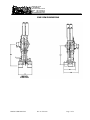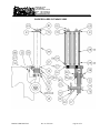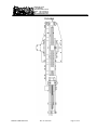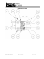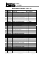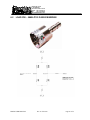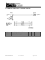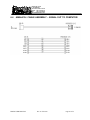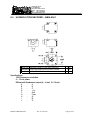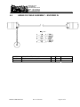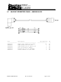
1
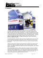
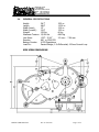
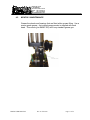
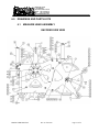
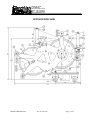
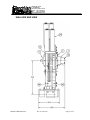
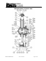
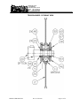
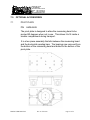
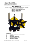
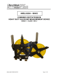
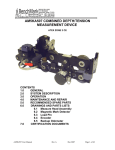
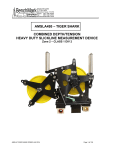
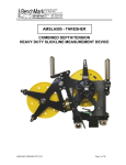
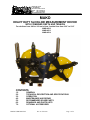
36220 FM 1093
P. O. BOX 850
Simonton,Texas 77476
Phone: 281.342.6415
Fax:
281.342.4848
benchmarkwireline.com
MAKO
HEAVY DUTY SLICKLINE MEASUREMENT DEVICE
WITH COMBINED DEPTH AND TENSION
For wirelines from .092 to .160 and e-lines / braided lines from 3/16” to 5/16”
AMSLA512
AMSLA513
AMSLA514
CONTENTS
1.0
2.0
3.0
4.0
5.0
6.0
7.0
MAKO USER MANUAL
GENERAL
TECHNICAL DESCRIPTION AND SPECIFICATIONS
OPERATION
MAINTENANCE AND REPAIR
RECOMMENDED SPARE PARTS
DRAWINGS AND PARTS LISTS
OPTIONAL ACCESSORIES
Rev A Feb 2010
Page 1 of 33
36220 FM 1093
P. O. BOX 850
Simonton,Texas 77476
Phone: 281.342.6415
Fax:
281.342.4848
benchmarkwireline.com
1.0 GENERAL
The "MAKO” Slickline Measuring Device is a heavy duty two wheeled device which
accurately measures both wireline depth and tension. It minimizes wire abrasion and
fatigue by using a non reverse bend configuration. The device is designed to be mounted
in front of the wireline drum on a spooling mechanism. Linear bearings in the mount allow
it to slide back and forth in front of the drum so the wire can be spooled evenly. Spooling
rollers and pressure wheels are provided to keep the wire in the wheels at low or no
tension. An optional "turn table" is available which allows the head to be pivoted 90
degrees for shipping protection.
This measuring head is unique from previous versions in that the wireline can be removed
from the measuring head without cutting off the re-head. The wireline can be removed
from the side. The guide rollers are slotted so they can be slid out of the way to remove
the wireline.
Tension is measured from a load pin which also serves as the axle for the tension wheel.
Since the two wheels are opposite each other, the wire completely wraps around both
wheels. This creates a relatively high signal at the load pin which provides a very accurate
tension measurement.
With the BenchMark Winchman's Panel, depth can be accurately measured on different
sized lines without changing wheels. This is done electronically by the panel using the
depth information provided by an encoder. Changes in wire size are accounted for by the
panel software. Wire stretch can also be automatically calculated by the panel. An
adapter is provided to drive a standard mechanical counter.
MAKO USER MANUAL
Rev A Feb 2010
Page 2 of 33
36220 FM 1093
P. O. BOX 850
Simonton,Texas 77476
Phone: 281.342.6415
Fax:
281.342.4848
benchmarkwireline.com
2.0 TECHNICAL DESCRIPTION AND SPECIFICATIONS
2.1
WIRE PATH:
The wire runs from the well around the measure wheel (wheel nearest drum) then
around the tension wheel and back across the top of the measuring wheel onto the
drum. Even though the wire runs side by side across the top of the measure
wheel, the system is designed to prevent wire to wire rub. The tension wheel is
tilted slightly with respect to the measuring wheel so that the wire enters the wheel
on one side of the groove and exits the wheel on the opposite side of the groove.
Guide rollers are aligned to assist in keeping the wire on the proper side of the
groove.
The wire runs through a non reversed bend configuration (i.e. the wire is always
bent in the same direction). This minimizes wire fatigue due to bending the wire in
opposite directions each time it passes through the measuring head. The large
wheel radius minimizes the effects of fatigue and promotes longer wire life,
especially with larger diameter wirelines.
Guide rollers are installed on the tension wheel to keep the wire in the groove. A
spring mounted guide roller is used on the measure wheel to ensure the wire is
always pressed tightly against the measure wheel to prevent wire slippage at low
tension to minimize measurement error. The spring tightly presses the wire
against the wheel regardless of wire size. The spring force keeps the wire turning
the wheel even with sudden changes of direction during jarring action. A
composite guide roller is mounted above the measure wheel to keep the wire in the
groove when wireline tension is relaxed such as during transport and rigup.
2.2
DEPTH MEASUREMENT:
Depth measurement is made by wrapping the wire around the measuring wheel
which has a precision machined groove. The wheel groove has a circumference
of 20.xx”with .125 wire installed. The wheel is hardened to greater than Rockwell
58 by using a special heat treat process. This minimizes wheel wear to maximize
wheel life.
This measuring head is capable of providing three completely independent depth
measurements, a mechanical counter, an optical encoder, and a magnetic
pickup.
The optical encoder provides a high resolution measurement to the BenchMark
Wireline Products hoistman’s panel. With this panel depth and line speed can be
accurately measured on different sized lines without changing wheels. This is
done electronically by the panel. Changes in wire size are accounted for by the
panel software. Wire stretch can also be automatically calculated by the panel.
MAKO USER MANUAL
Rev A Feb 2010
Page 3 of 33
36220 FM 1093
P. O. BOX 850
Simonton,Texas 77476
Phone: 281.342.6415
Fax:
281.342.4848
benchmarkwireline.com
The panel operates on 12-24vdc and supplies the necessary power to the encoder
and load pin.
A backup depth system is available to provide another independent depth
measurement. Depth is measured by a frictionless magnetic pickup mounted in
the measuring head. The pickup consists of magnets imbedded in the measure
wheel coupling and two hall affect devices mounted next to the shaft. This
provides a quadarature type measurement. A small display panel is mounted
inside a wireline unit. The panel is designed to be connected to an external AC or
DC supply or operate off internal batteries for up to 15 hours between charges. In
the event of an external power interruption, the unit automatically switches to
battery power. The system is designed to operate without intervention from the
user. When external power fails, the depth display is maintained by the batteries.
A switch on the front of the panel allows different sizes of wire to be measured
accurately without changing the measuring wheels.
The mechanical measurement is made by connecting a “speedometer” cable to
the hub of the measuring wheel. A “Veedor Root” type counter can be used. Step
down adapters are needed to convert from a 1:5 to a 1:1 measurement (adapters
on the wheel and in the counter). The mechanical system cannot be adjusted for
different wire sizes so a wheel with a different sized groove must be installed to
make the mechanical measurement correct.
MAKO USER MANUAL
Rev A Feb 2010
Page 4 of 33
36220 FM 1093
P. O. BOX 850
Simonton,Texas 77476
Phone: 281.342.6415
Fax:
281.342.4848
benchmarkwireline.com
2.3
TENSION SPECIFICATIONS:
The wheel nearest the well rotates on an axle pin that is instrumented with strain
gauges. These strain gauges produce an electrical signal proportional to the
magnitude of line tension. The wire always makes a complete 180 degree wrap
around the tension wheel so rig up angle does not affect the tension measurement.
The tension wheel is mounted on a self aligning bearing which allows the wheel to
properly align itself. This reduces any side forces that may be present which
increases the tension measurement accuracy.
TEMPERATURE STABILITY
<=
.015% full scale / deg F on zero
<=
.02% full scale / deg F on output
ACCURACY
1% full scale nominal
MAXIMUM LINE PULL:
15,000 lbs (6800 kg)
PASSIVE BRIDGE
POWER REQUIREMENTS:
12 vdc excitation
INTERFACE:
None – passive bridge only
STRAIN GAUGE OUTPUT
SHUNT = 12000 lbs line pull
15000 lbs = 2.0mV / V (1/2 line pull)
MAXIMUM LINE PULL:
15,000 lbs
(6800 kg)
DIFFERENTENTIAL VOLTAGE:
POWER REQUIREMENTS:+/– 15 vdc input power
INTERFACE:
Proprietary circuit board which
amplifies the load pin signals and
provides a 1.5v differential output.
0 vdc = 0 lbs
(0 kg)
1.2 vdc = 12000 lbs (5445 kg) - shunt cal
1.5 vdc = 15000 lbs (6804 kg)
4-20MA CURRENT LOOP
POWER REQUIREMENTS: +24vdc input power
INTERFACE:
Proprietary circuit board which
amplifies the load pin signals and
provides a 4-20ma current loop output.
4 ma
= 0 lbs
(0 kg)
16.8 ma = 12000 lbs (5445 kg) - shunt cal
20ma = 15000 lbs (2268 kg)
MAKO USER MANUAL
Rev A Feb 2010
Page 5 of 33
36220 FM 1093
P. O. BOX 850
Simonton,Texas 77476
Phone: 281.342.6415
Fax:
281.342.4848
benchmarkwireline.com
2.4
GENERAL SPECIFICATIONS:
Height:
Length
Width (base):
Width (overall):
Weight:
Maximum Tension:
Line Sizes:
Encoder:
Backup Counter:
Load Pin:
36.7"
.932 m
48.6"
1.234 m
12"
.305 m
12.8”
.325 m
132 lbs
60 kg
15,000 lbs
6800 kg
.092" – 5/16”
2.3 mm – 7.94 mm
600 or 1200 PPR
4 PPR Quadrature
Passive Bridge, 1.5v Differential, 4-20ma Current Loop
SIDE VIEW DIMENSIONS
MAKO USER MANUAL
Rev A Feb 2010
Page 6 of 33
36220 FM 1093
P. O. BOX 850
Simonton,Texas 77476
Phone: 281.342.6415
Fax:
281.342.4848
benchmarkwireline.com
END VIEW DIMENSIONS
MAKO USER MANUAL
Rev A Feb 2010
Page 7 of 33
36220 FM 1093
P. O. BOX 850
Simonton,Texas 77476
Phone: 281.342.6415
Fax:
281.342.4848
benchmarkwireline.com
3.0
SYSTEM OPERATION
3.1
Determine wireline size to be used – .092" to 5/16”
Since the wireline wraps around the depth wheel, the circumference of the
depth wheel will change with a change in wire size. The wheel size needs
to be corrected for wireline size in order to accurately measure depth.
These corrections are automatically made in the BenchMark hoistman's
panel by selecting the proper cable size using the menu. If a different panel
is used, the wheel size will need to be entered at this time.
3.2
Thread wire into measuring head from the front (no cable head installed)
using the following procedure:
1.
Run the wireline from the drum, through the drum side spooling
rollers, onto the left side (facing the drum) of the depth wheel.
2.
Pull the wireline across the depth wheel, under the spooling roller
mount around the tension wheel.
3.
Make sure the guide rollers are loose so the wireline can be installed
on the tension wheel.
4.
Pull the wireline from the bottom of the tension wheel around the
bottom of depth wheel, under the spring mounted tension roller
(mounted on the rear of the depth wheel), around the top of the
depth wheel (right side), and through the rig side spooling rollers.
5.
To open the spring mounted pressure roller, press on the back near
the spring or insert a 11/16” open end wrench into the pressure roller
pivot and pull back.
6.
After the wireline is installed, tighten the guide rollers. They should
be barely touching the wireline in the tension wheel. If they are
pressed too tightly against the wireline, the tension measurement will
be affected.
MAKO USER MANUAL
Rev A Feb 2010
Page 8 of 33
36220 FM 1093
P. O. BOX 850
Simonton,Texas 77476
Phone: 281.342.6415
Fax:
281.342.4848
benchmarkwireline.com
3.3
Install wire into measuring head from the side with cable head installed
using the following procedure:
1.
Loosen the guide wheels and slide them up.
2.
Loosen the spacer plates above the spooling rollers and turn them 90
degrees.
3.
Install wireline over the wheels from the side of the frame
4.
Pull the wireline from the bottom of the tension wheel around the
bottom of depth wheel, under the spring mounted tension roller
(mounted on the rear of the depth wheel), around the top of the
depth wheel (right side), and through the rig side spooling rollers.
5.
To open the spring mounted pressure roller, press on the back near
the spring or insert a 11/16” open end wrench into the pressure roller
pivot and pull back.
6.
After the wireline is installed, tighten the guide rollers. They should
be barely touching the wireline in the tension wheel. If they are
pressed too tightly against the wireline, the tension measurement will
be affected.
3.4
Make sure line is lying slack and head is free to move. Press the T Zero
button and tension value should read 0.
3.5
Press the T Cal button and verify that the tension reads close to 5000 lbs.
(2270 kg).
3.6
Press the Zero Depth button to set the depth to zero when the tool is
hanging at the zero point.
3.7
Simultaneously press the enable and zero button on the backup display
panel at this time to zero it.
3.8
At this point, the system is ready to log.
MAKO USER MANUAL
Rev A Feb 2010
Page 9 of 33
36220 FM 1093
P. O. BOX 850
Simonton,Texas 77476
Phone: 281.342.6415
Fax:
281.342.4848
benchmarkwireline.com
4.0
MAINTENANCE AND REPAIR
4.1
PRE AND POST JOB CHECKS
Between jobs, check the measuring and guide wheels for looseness, play, out-ofroundness, worn or rough sounding bearings, or other mechanical conditions that
could affect measurement accuracy.
Visually inspect the interiors of the electrical connectors for the encoders and
electronic load axle for dirt and evidence of insulation breakdown. Clean or
replace as necessary. Install dust caps on the connectors if the cables are
removed.
Manually rotate each wheel by hand to verify its condition. Inspect the depth
measuring wheel for signs of abnormal wear diameter changes, or shaft play that
can affect measurement accuracy.
Do not pressure wash bearings or
electrical parts
MAKO USER MANUAL
Rev A Feb 2010
Page 10 of 33
36220 FM 1093
P. O. BOX 850
Simonton,Texas 77476
Phone: 281.342.6415
Fax:
281.342.4848
benchmarkwireline.com
4.2
MONTHLY MAINTENANCE
Grease the wheels and bearings that are fitted with a grease fitting. Use a
marine grade grease. An inverted grease nozzle is supplied with each
head. This nozzle (p/n AM5KP130) will fit any standard grease gun.
MAKO USER MANUAL
Rev A Feb 2010
Page 11 of 33
36220 FM 1093
P. O. BOX 850
Simonton,Texas 77476
Phone: 281.342.6415
Fax:
281.342.4848
benchmarkwireline.com
4.3
ASSEMBLY / DISASSEMBLY PROCEDURES
4.3.1 ELECTRONIC LOAD PIN REMOVAL
The electronic load pin is held in place by one retaining ring on the outer
end of its shaft. Remove the retaining ring. The load pin can then be
removed from the mounting frame.
4.3.2 BACKUP DEPTH MAGNETIC PICKUP REMOVAL AND INSTALLATION
The backup depth magnetic pickup is mounted to the encoder adapter. It is
held in place by four screws. Remove the screws and the pickup can then
be removed. The pickup must be properly oriented to work correctly. The
slot should be oriented to the top. The top side is the encoder side. Ensure
that an o-ring is inserted between the plastic housing and the mount. An
additional o-ring is used between the connector and the housing to keep
moisture out.
If the backup display is counting backward (i.e. counting negative when
going down hole), simply rotate the pickup 180 degrees to change the
direction.
4.3.3 ENCODER COUPLING INSTALLATION
To install the encoder coupling, first remove the plug in the encoder adapter.
Next, install the encoder on the outer encoder adapter.
Using a hex head wrench, tighten the set screws on the coupling then
replace the plug.
MAKO USER MANUAL
Rev A Feb 2010
Page 12 of 33
36220 FM 1093
P. O. BOX 850
Simonton,Texas 77476
Phone: 281.342.6415
Fax:
281.342.4848
benchmarkwireline.com
5.0
RECOMMENDED SPARE PARTS
Following is a list of recommend spare parts. Parts designated REMOTE are
recommended only for areas that have a very difficult time getting parts shipped to.
For all other areas, it should not be necessary to stock the REMOTE parts locally.
ITEM
1
2
12
13
33
50
51
52
53
54
99
P/N
AMSLM559
AMSLA560
AMSLA162
AMSLA163
AMSLM153
AMSLM033
AMSLP061
C276M055
AMSLP213
AMSLP031
AM3KP204
AM5KP130
MAKO USER MANUAL
DECSRIPTION
WHEEL MEASURING 20" 5/16 MAKO
WHEEL ASSY TENS 20" 5/16 MAKO
WHEEL ASSY PRESS RLR 1/4 TENSN
WHEEL ASSY PRESS ROLLER MEASR W/BEARING
SHAFT LOAD PIN REPL 1.5OD 2 WH
ROLLER KEEPER UNIVERSAL
ENCODER HD2.5D-0-SS-37F-1200
COUPLING ENCODER H25 TO RELIANCE ADTPR
BEARING SPHERE-ROL 65MM ID
BEARING BALL 50MM 2-ROW
BEARING BALL 20MM SST ABEC-1
NOZZLE GREASE FITTNG FLUSH
Rev A Feb 2010
QTY
1
1
2
1
1
1
1
1
1
1
4
1
Page 13 of 33
36220 FM 1093
P. O. BOX 850
Simonton,Texas 77476
Phone: 281.342.6415
Fax:
281.342.4848
benchmarkwireline.com
6.0
DRAWINGS AND PARTS LISTS
6.1
MEASURE HEAD ASSEMBLY
ENCODER SIDE VIEW
MAKO USER MANUAL
Rev A Feb 2010
Page 14 of 33
36220 FM 1093
P. O. BOX 850
Simonton,Texas 77476
Phone: 281.342.6415
Fax:
281.342.4848
benchmarkwireline.com
OPPOSITE SIDE VIEW
MAKO USER MANUAL
Rev A Feb 2010
Page 15 of 33
36220 FM 1093
P. O. BOX 850
Simonton,Texas 77476
Phone: 281.342.6415
Fax:
281.342.4848
benchmarkwireline.com
WELLSIDE END VIEW
MAKO USER MANUAL
Rev A Feb 2010
Page 16 of 33
36220 FM 1093
P. O. BOX 850
Simonton,Texas 77476
Phone: 281.342.6415
Fax:
281.342.4848
benchmarkwireline.com
DRUM END VIEW
MAKO USER MANUAL
Rev A Feb 2010
Page 17 of 33
36220 FM 1093
P. O. BOX 850
Simonton,Texas 77476
Phone: 281.342.6415
Fax:
281.342.4848
benchmarkwireline.com
MEASURE WHEEL CUTAWAY VIEW
MAKO USER MANUAL
Rev A Feb 2010
Page 18 of 33
36220 FM 1093
P. O. BOX 850
Simonton,Texas 77476
Phone: 281.342.6415
Fax:
281.342.4848
benchmarkwireline.com
TENSION WHEEL CUTAWAY VIEW
MAKO USER MANUAL
Rev A Feb 2010
Page 19 of 33
36220 FM 1093
P. O. BOX 850
Simonton,Texas 77476
Phone: 281.342.6415
Fax:
281.342.4848
benchmarkwireline.com
GUIDE ROLLERS CUTAWAY VIEW
MAKO USER MANUAL
Rev A Feb 2010
Page 20 of 33
36220 FM 1093
P. O. BOX 850
Simonton,Texas 77476
Phone: 281.342.6415
Fax:
281.342.4848
benchmarkwireline.com
TOP VIEW
MAKO USER MANUAL
Rev A Feb 2010
Page 21 of 33
36220 FM 1093
P. O. BOX 850
Simonton,Texas 77476
Phone: 281.342.6415
Fax:
281.342.4848
benchmarkwireline.com
FRAME ROLLER VIEW
MAKO USER MANUAL
Rev A Feb 2010
Page 22 of 33
36220 FM 1093
P. O. BOX 850
Simonton,Texas 77476
Phone: 281.342.6415
Fax:
281.342.4848
benchmarkwireline.com
MEASURE HEAD ASSEMBLY PARTS LIST
ITEM 1 2 3 4 5 6 7 8 9 9 9 10 11 12 13 14 15 16 17 18 19 20 20 20 21 22 23 24 25 26 27 28 29 30 31 32 PART NUMBER AMSLM559 AMSLA560 AMSLM516 AM3KM040 AMSLM522 AMSLM568 AMSLM539 AMSLM521 AMSLA529 AMSLA555 AMSLM044 AMSLM283 AMSLM533 AMSLA162 AMSLM569 AMSLM228 AMSLM449 AMSLM550 AMSLM251 AMSLM515 AMSLM585 AMSLM153 AMSLP153 AMSLA215 AMSLA550B AM3KM050 AMSLM030 AMSLM531 AMSLM565 AMSLM514 AMSLM230 AMSLM217 AMSLM218 AMSLM219 AMSLM584 AMSLM053 AMSLM555 MAKO USER MANUAL
DESCRIPTION WHEEL MEASURING 20" 5/16 MAKO WHEEL ASSY TENS 20" 5/16 MAKO ADAPTER MEAS WHL SHAFT 50MM ADAPTER ENCODER H25D/H20 MAG ADAPTER COUNTER HD RT ANGL DRV MOUNT GUIDE ROLR FRONT MAKO PLATE BASE OPEN MAKO PLATE SPACER GUIDE ROLLER VERT SWIVEL ASSY TURNTABLE W/LINEAR ASSY TROLLEY 1‐1/2 HD ROLLER BRACKET LEVELWIND CHAIN SPACER KEEPER ROLLER 0.34 THK ROLLER KEEPER TOP MAKO WHEEL ASSY PRESS RLR 1/4 TENSN ROLLER SLACK HORIZ LEVELWIND NUT 7/16‐14 TEE SLOT SST GUIDE SPRING PRESS WHL 2WC MOUNT GUIDE ROLR REAR MAKO MOUNT PIVOT PRESS WHEEL 2WC SHAFT MEAS WHL 50MM ENCDR/RT PLATE ORIENTATION L PIN MAKO SHAFT LOAD PIN REPL 1.5OD 2 WH PIN LOAD 30K# 1‐1/2OD 2.0mV/V ASSY LOAD AXLE 4‐20mA 1.50 DIA ASSY LOAD AXLE 0‐1.5V 1‐1/2DIA COUPLING ENCDR W/BKUP MAGNETS BUSHING FRAME 2 WHEEL COUNTER BUSHING TENS WHL 1‐1/2 LP MAKO BUSHING L/P 1‐1/2 W/ANTI‐ROT WASHER MEAS WHL SHAFT MAKO BUSHING FRAME 3/8‐16 SHARK SHAFT GUIDE ROLLER VERT LVLWND TBG SPACER GUIDE ROLLER LVLWND ROLLER GUIDE VERT LEVELWIND SCREW ANTI‐ROTN TENS WHL MAKO BUSHING FLANGE PRESS WHEL 3/8 BUSHING FLANGE PRESS WHEL 5/16 Rev A Feb 2010
QTY 1
1
1
1
1
1
1
2
0
0
2
1
1
3
2
3
2
1
1
1
1
0
0
0
0
1
10
2
1
1
4
4
4
4
1
1
1
REFERENCE OPTION OPTION OPTION OPTION USED ON AMSLA514 USED ON AMSLA513 USED ON AMSLA512 OPTION Page 23 of 33
36220 FM 1093
P. O. BOX 850
Simonton,Texas 77476
Phone: 281.342.6415
Fax:
281.342.4848
benchmarkwireline.com
33 34 35 36 37 38 39 40 41 42 43 44 45 46 47 48 49 50 50 51 51 52 53 54 55 56 57 58 59 60 61 62 63 64 65 67 68 69 70 71 72 AM3KM034 AMSLM534 AMSLM040 AMSLM580 AMSLM080 AMSLM540 AMSLM583 AMSLM582 AMSLM570 AMSLM518 AMSLM229 AMSLM530 AMSLM545 AMSLM546 AMSLM547 AMSLP522 AM5KA055 AMSLP061 AMS7P131 AM5KM073 AMS1P090 AMSLP213 AMSLP031 AM3KP204 AMSLP005 AMSLP009 AMSLP105 AMSLP568 AMSLP278 AMSLP015 AM5KP129 C276P014 C276P046 C276P035 AMS1P058 C276P036 AM5KP144 AMSLP047 AMSLP247 AMS1P014 AM5KP071 MAKO USER MANUAL
BLOCK WEAR 0.75 X 2.50 TOOLSTL SPACER KEEPER ROLLER MAKO SPACER FRAME 2 WHEEL COUNTER SPACER PRESSURE WHEEL 1.07 THK SPACER PRESSURE WHEEL 0.32 THK SPACER FRAME 2" MAKO SPACER KEEPER ROLLER 0.61 THK SPACER PRESSURE WHEEL 1.47 THK BUSHING FRAME 7/16‐14 MAKO TBG SPACER SLACK ROLLER LVLWND BUSHING FRAME TUBE BUSHING FRAME 3/8‐16 MAKO PLATE FRAME 5/8 OPEN SIDE MAKO PLATE FRAME 5/8 MIDDLE MAKO PLATE FRAME 3/8 OUTER MAKO RING RETNG INT 4.750 LT DUTY ASSY ENCODER BACKUP MAGNETIC ENCODER S25HA‐37F‐1200‐ABZC‐69 ENCODER S25‐HA‐37F‐600‐ COUPLING MOD ENCDR 0.250/0.375 COUPLING OLDHAM ENCODER BEARING SPHERE‐ROL 65MM ID BEARING BALL 50MM 2‐ROW BEARING BALL 20MM SST ABEC‐1 BEARING PILLOW BLOCK 1‐1/2 BEARING BRZ FLANGED 3/8" ID RING RETNG EXT 1.500 SHAFT SST RING RETNG INT 4.375 LT DUTY SPRING COMP 2.00 OAL 1.218 OD KEY 1/4 X 7/8 WOODRUFF SST FITTING GREASE FLUSH STRAIGHT INSERT 1/4‐20 HELI‐COIL #R1185 WASHER #6 LOCK SS WASHER #10 LOCK SS WASHER 3/8 LOCK SS WASHER 1/4 LOCK SS WASHER 1/4 LOCK SS HIGH COLLAR WASHER 7/16 LOCK SST WASHER 7/16 HEAVY FLAT SST O‐RING 2‐152 BUNA N ENC ADPTR O‐RING 2‐141 BUNA N H25 ENCDR Rev A Feb 2010
1
1
5
2
2
6
3
1
1
2
1
6
1
1
1
2
0
0
0
0
0
1
2
8
3
2
1
2
1
1
3
29
4
4
10
15
34
9
15
1
1
TENSION WHEEL OPTION OPTION OPTION OPTION OPTION ENCODER ADAPTER ENCODER Page 24 of 33
36220 FM 1093
P. O. BOX 850
Simonton,Texas 77476
Phone: 281.342.6415
Fax:
281.342.4848
benchmarkwireline.com
73 74 75 75 76 77 78 79 80 81 84 85 86 87 88 89 90 91 92 93 94 94 95 97 98 99 C276P042 C276P041 AMS1P072 C276P016 AMSLP112 AMSLP059 C276P021 AMSLP244 AMSLP243 AMSLP058 AMSLP071 AMSLP072 AMSLP069 AMS1P048 AM3KP027 AMSLP025 AM3KP026 AM3KP029 C276P030 AM5KP117 AMS1P052 AMS1P053 AM5KP045 C276P331 AMSLP023 AM5KP130 MAKO USER MANUAL
O‐RING 2‐016 BUNA N O‐RING 2‐017 BUNA N PLUG 3/8 NPT SS NUT 1/4‐20 HEX SST BEARING BALL 12MM SST NUT 7/16‐14 SST NUT 7/8‐14 ELASTIC STOP SST SCREW 7/16‐14 X 4 SOC HD SCREW 7/16‐14 X 3‐3/4 SOC HD SCREW 7/16‐14 X 1 SOC HD SCREW 3/8‐16 X 2‐1/2 BUT HD SS SCREW 3/8‐16 X 2 BUT HD SS SCREW 3/8‐16 X 1‐3/4 BUT HD SS SCREW 1/4‐20 X 3/4 SOC HD SST SCREW 1/4‐20 X 1‐1/2 SOC HD SS SCREW 1/4‐20 X 1 SOC HD SST SCREW 1/4‐20 X 2 SOC HD CAP SS SCREW 1/4‐20 X 1‐3/4 SOC HD SS SCREW 1/4‐20 X 1 FH SOC SST SCREW 1/4‐20 X 5/8 BTN HD SST SCREW 10‐24 X 5/8 SOC HD SST SCREW 10‐24 X 2 SHCS SST SCREW 10‐24 X 1/2 FH SOC SST SCREW 6‐32 X 1/2 PHIL PAN SST BOLT SHOULDER 3/8 X 1‐3/4 SST NOZZLE GREASE FITTNG FLUSH Rev A Feb 2010
1
1
1
12
4
1
1
3
3
4
8
1
1
8
17
14
8
1
9
1
4
4
4
4
1
1
BACKUP CONNECTOR BACKUP HOUSING Page 25 of 33
36220 FM 1093
P. O. BOX 850
Simonton,Texas 77476
Phone: 281.342.6415
Fax:
281.342.4848
benchmarkwireline.com
6.2
LOAD PIN – AMSLP153 PASSIVE BRIDGE
MAKO USER MANUAL
Rev A Feb 2010
Page 26 of 33
36220 FM 1093
P. O. BOX 850
Simonton,Texas 77476
Phone: 281.342.6415
Fax:
281.342.4848
benchmarkwireline.com
6.3 AMS4A353 CABLE ASSY – PASSIVE LOAD PIN
AM5KP058
AMS7P014
AM5KP059
AMS4P221
CONN KPT08P10-6S RT ANGLE PLUG
CONN MS3106E-18-9S
DUST CAP KPT8010C CANNON
CABLE 20/8C ALPHA -20 DEG
MAKO USER MANUAL
Rev A Feb 2010
1
1
1
20
EA
EA
EA
FT
LOAD PIN END
Page 27 of 33
36220 FM 1093
P. O. BOX 850
Simonton,Texas 77476
Phone: 281.342.6415
Fax:
281.342.4848
benchmarkwireline.com
6.4
AMS4A134 CABLE ASSEMBLY – SIGNAL OUT TO COMPUTER
MAKO USER MANUAL
Rev A Feb 2010
Page 28 of 33
36220 FM 1093
P. O. BOX 850
Simonton,Texas 77476
Phone: 281.342.6415
Fax:
281.342.4848
benchmarkwireline.com
6.5
HI RESOLUTION ENCODER – AMSLA061
13 AMSLA061 ENCODER H25D-SS-1200-ABZC-69-S18-15
36 AM5KM073 COUPLING MOD ENCDR 0.250/0.375 BORE
1 EA
1 EA
44 AMS1P071 DUST CAP MS25043-16DA
1 EA
Specifications
1200 Pulses per revolution
5 – 15 vdc power
Differential Quadrature output (A – A not, B – B not)
A
A
B
B
C
Z
D
+ 5v
F
Gnd
G
Case
H
A\
I
B\
J
Z\
MAKO USER MANUAL
Rev A Feb 2010
Page 29 of 33
36220 FM 1093
P. O. BOX 850
Simonton,Texas 77476
Phone: 281.342.6415
Fax:
281.342.4848
benchmarkwireline.com
6.6
AMS4A125 CABLE ASSEMBLY – ENCODER IN
AMS1P028
AMS4P221
AMS1P029
CONN MS3106E-18-1S
CABLE 20/8C ALPHA -20 DEG
DUST CAP MS25042-18DA
MAKO USER MANUAL
Rev A Feb 2010
2
20
1
EA
FT
EA
Page 30 of 33
36220 FM 1093
P. O. BOX 850
Simonton,Texas 77476
Phone: 281.342.6415
Fax:
281.342.4848
benchmarkwireline.com
6.7
BACKUP ODOMETER CABLE – AM5KA024-020
P/N
--------------AMS4P222
AM5KP057
AM5KP058
AM5KP059
AM5KA034
AMS4P210
MAKO USER MANUAL
Description
-----------------------------CABLE 20/4C ALPHA 25154 BLACK
CONN KPT06F10-6P STR PLUG
CONN KPT08P10-6S RT ANGLE PLUG
DUST CAP KPT8010C CANNON
BUSHING #9779-513-4 AMPHENOL
TUBING SHRINK 0.50 ADH LINED
Rev A Feb 2010
Qty Required
---------------20
1
1
2
2
1
UM
--FT
EA
EA
EA
EA
EA
Page 31 of 33
36220 FM 1093
P. O. BOX 850
Simonton,Texas 77476
Phone: 281.342.6415
Fax:
281.342.4848
benchmarkwireline.com
7.0
7.1
OPTIONAL ACCESSORIES
PIVOT PLATE
P/N
AMSLA529
The pivot plate is designed to allow the measuring head to be
pivoted 90 degrees when not in use. This allows it to fit inside a
smaller compartment during transport.
It is a two piece assembly that sits between the measuring head
and the horizontal spooling bars. The bearings are removed from
the bottom of the measuring head and bolted to the bottom of the
pivot plate.
MAKO USER MANUAL
Rev A Feb 2010
Page 32 of 33
36220 FM 1093
P. O. BOX 850
Simonton,Texas 77476
Phone: 281.342.6415
Fax:
281.342.4848
benchmarkwireline.com
7.2
LOAD PIN REPLACEMENT PIN
P/N AMSLM513
In the event the load pin needs to be removed for calibration or
repair, a pin can be inserted in its place to support the tension
wheel.
At this time a hydraulic load cell can be used to provide tension.
The depth portion of the measuring head will still function
properly and accurately.
A 1” diameter shoulder bolt can be used as a substitute. The bolt
needs to have at least a 2-1/2” shoulder. It should be of at least
grade 8 to support the potential load.
MAKO USER MANUAL
Rev A Feb 2010
Page 33 of 33