1
KIT-VR5400-TP
User's Manual
RealTimeEvaluator
KIT-VR5400-TP
User’ s Manual
Revision History
Rev.0.8
Jul. 19,1999
Preliminary 1st edition
Rev.0.81 Jul. 26, 1999
Modified
Rev.0.82 Aug. 11, 1999
Modification to description of pin mask
Rev.1.00 Sep. 24, 1999
Official 1st edition
* Addition of parameter to env command
* Addition of cacheinit and cacheflush
1
KIT-VR5400-TP
User’ s Manual
CONTENTS
1. OVERVIEW....................................................................................................................................... 3
2. HARDWARE SPECIFICATIONS ....................................................................................................... 4
Emulation........................................................................................................................................... 4
Host system and interface .................................................................................................................. 4
3. RTE FOR WIN32............................................................................................................................... 5
Starting ChkRTE32.exe ...................................................................................................................... 5
4. INITIALIZATION COMMANDS.......................................................................................................... 6
env command..................................................................................................................................... 6
rom command .................................................................................................................................... 7
5. INTERFACE SPECIFICATIONS ........................................................................................................ 8
Pin arrangement table ........................................................................................................................ 8
Connectors......................................................................................................................................... 8
Wire length......................................................................................................................................... 8
Layout of the connectors on the board ................................................................................................ 9
6. PRECAUTIONS .............................................................................................................................. 10
Precautions related to operation ....................................................................................................... 10
Precautions related to functions ........................................................................................................ 10
2
KIT-VR5400-TP
User’ s Manual
1. OVERVIEW
KIT-VR5400-TP is a product to use RTE-200-TP. It is an In-circuit emulator for NEC's RISC processor,
VR5464 and VR5432 by using KIT-VR5400-TP and RTE-200-TP together.
Please read a User's Manual of RTE-200-TP together.
This product comes with the following components. First check that none of the components are
missing.
• RTE for Win32 Setup Disk
• User's manual (This manual)
• License sheet
3
KIT-VR5400-TP
User’ s Manual
2. HARDWARE SPECIFICATIONS
Emulation
Target device
VR5464, VR5432
RTE-TP
RTE-200-TP
Emulation functions
Operating frequency
Max: 66 MHz (Bus clock)
Interface
JTAG/N-Wire
Break functions
Break using an execution address event (*2)
1
Break that can be set using an access event (*3)
1
S/W break points
100
Step breaks
Supported
Manual breaks
Supported
Trace functions (*4)
Trace data bus
4 bits
Trace memory
4 bits x 128K words
Trigger that can be set using an execution address
event (*2)
1
Trigger that can be set using an access event (*3)
1
Trace delay
0 - 1FFFFh
Trace clock
66 MHz (max.)
Disassembled trace data display function
Provided
ROM emulation functions
Memory capacity
4 M-Byte
Access time
50 ns
Number of ROMs that can be emulated
DIP-32pin-ROM (8-bit ROM)
4 (max.)
DIP-40/42pin-ROM (16-bit ROM)
2 (max.)
STD-16BIT-ROM connector
2 (max.)
Types of ROMs that can be emulated
DIP-32-ROM probe(bits)
1M, 2M, 4M, 8M (27C010/020/040/080)
DIP-40-ROM probe(bits)
1M, 2M, 4M (27C1024/2048/4096)
DIP-42-ROM probe(bits)
8M, 16M (27C8000/16000)
Bus width specification (bits)
8/16/32
Target ROM capacity (bits)
512K, 1M, 2M, 4M, 8M, 16M(*1)
Pin mask functions
*1
*2
*3
*4
NMI, INT
An 8-bit ROM probe supports ROMs of up to 8M bits.
Break and execution address event for trigger are shared.
Break and access event for trigger are shared.
The execution speed drops during trace.
Host system and interface
Item
Description
Target host machine
PC 9800 Series and DOS/V PCs
Debugger
GHS-Multi, PARTNER/Win (Windows95/98/NT)
Interface
PC card Type II (version 2.1 of the PCMCIA specifications/version 4.2 of the JEIDA
specification or later)
PC 9800 (C bus), PC/AT (ISA bus and PCI bus), or LAN-BOX
Power supply
AC adapter (in: 100 V out: +5 V, 2A)
4
KIT-VR5400-TP
User’ s Manual
3. RTE FOR WIN32
This chapter describes the setting of RTE for WIN32, with the focus on the aspects specific to KITVR5400-TP.
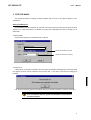
Starting ChkRTE32.exe
Start ChkRTE32.exe after RTE-100-TP has been connected to the user system and the power to all the
devices is on. When RTE-200-TP is installed for the first time, ChkRTE32.exe must be started once to
select RTE.
<Selecting RTE>
Set the Setup dialog box of ChkRTE32.exe, as follows.
VR5432-TP(xxx)
Specify the interface to be used.
Specify an address as necessary.
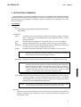
<Function test>
If RTE-200-TP is properly connected to the user system and capable of debugging, the following dialog
box appears upon the normal completion of the function test. In this state, control from the debugger is
possible.
If an error occurs during the test, the N-Wire cable is not properly connected. Check its connection.
Perform the ChkRTE32.exe function test after the RTE-200-TP has
been connected to the user system and the power to all the devices
has been turned on.
5
KIT-VR5400-TP
User’ s Manual
4. INITIALIZATION COMMANDS
Before debugging can be started, initialization is required. The following explains initialization using the
appropriate internal commands. If the debugger offers a means of initialization, they may be used instead.
(See Appendix A for an explanation of starting the internal commands and an explanation of the other
internal commands.)
env command
[Format]
env [[!]auto] [[!]nmi] [[!]int] [jtag{25|12}] [[!]verify] [[!]hispeed]
[work ADDR]
[Parameters]
[!]auto:
If a break point is encountered during execution, the break point causes a temporary
break. Choose [Auto] to automatically perform the subsequent execution. Choose
[!auto] to suppress it.
[!]nmi:
Specifies whether the NMI pin is to be masked. Enter ! if it is not to be masked.
[!]int:
Specifies that pins INTxx are to be masked. Enter ! if they are not to be masked.
jtag[12|25]:
Specifies the JTAG clock (12.5 MHz|25 MHz) for N-Wire. Initial value of rte4win32 is
[!]verify:
12.5 MHz (Ver. 4.37 or later) or 25 MHz (before Ver. 4.37).
Specifies the verification after writing memory is set. Enter ! if it is not to be set.
Remark The CPU also accesses an area that emulates ROM (jread or equivalent).
Therefore, this command is useful for testing the area during downloading.
Note, however, that the processing speed slows down.
[[!]hispeed]:
Specifies high-speed mode to write data to memory. ! specifies the normal mode.
Remark The high-speed mode can be specified on condition that the ROM probe be
connected. If this mode is specified, a control program temporarily located in the
ROM emulated is executed in the foreground only when data of 128 bytes or
more are contiguously written. Use this mode after the hardware has been
completely debugged because the CPU must be able to access the ROM
correctly. In normal mode, data can be written to ROM via JTAG.
[work ADDR]: Specifies an area for clearing the cache or executing initialization processing. Be sure
to specify the RAM on uncache immediately after starting the system. The VR5400
requires RAM on the user system for cache processing. The monitor uses an area of
128 bytes from the specified address destructively.
Remark As this area is not used unless the cache area is accessed, confirm that the RAM
can be accessed in the uncache area before accessing the cache area.
[Function]
The env command sets the emulation environment. Enter only those parameters that need to be
changed. Parameters may be entered in any order. If the same parameter is entered twice, only
the last entry is valid.
6
KIT-VR5400-TP
User’ s Manual
rom command
[Format]
rom [ADDR [LENGTH]] [512k|1m|2m|4m|8m|16m] [rom8|rom16] [bus8|bus16|bus32] [little|big]
[Parameters]
ADDR [LENGTH]:
ADDR:
Specifies an area to be emulated.
Specifies a start address. An error occurs if the specified start address
does not match the lowest address of the ROM to be emulated
(boundary of the ROM).
LENGTH:
Number of bytes of the ROM to be emulated. (Must be specified in
boundary units of 4 bytes.)
512k|1m|2m|4m|8m|16m:
Specifies the bit size of the ROM to be emulated.
Sizes from 512K bits to 16M bits can be specified. For the 27C1024, for
example, specify 1M bits.
rom8|rom16:
Specifies the number of data bits of the ROM to be emulated.
Either 8 bits or 16 bits can be specified. If a DIP-32-ROM probe is used,
choose rom8; if a DIP-40/42-ROM probe is used, choose rom16.
bus8|bus16|bus32:
Specifies the ROM bus size in the system to be emulated. 8 bits, 16
bits, or 32 bits can be specified.
Little|big:
Specifies the endian of the rom data. If little endian is specified during
downloading, the binary image of a file is written as is. If big endian is
specified, the data of the high-order bytes and low-order bytes are
exchanged depending on the bus size of the ROM.
[Function]
The rom command sets the ROM emulation environment. Enter only the parameters that need to be
changed. Parameters may be entered in any order. If the same parameter is entered twice, only the
last entry is valid. The initial value of LENGTH is 0 (not used).
7
KIT-VR5400-TP
User’ s Manual
5. INTERFACE SPECIFICATIONS
This chapter describes the specifications of the connectors used for control that are required for the user
system.
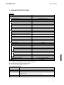
Pin arrangement table
Pin number
Signal name
Input/output (user side)
A1
CLKOUT
Output
22 - 33 Ω series resistor (recommended)
A2
TRCDATA0
Output
22 - 33 Ω series resistor (recommended)
A3
TRCDATA1
Output
22 - 33 Ω series resistor (recommended)
A4
TRCDATA2
Output
22 - 33 Ω series resistor (recommended)
A5
TRCDATA3
Output
22 - 33 Ω series resistor (recommended)
A6
TRCEND
Output
22 - 33 Ω series resistor (recommended)
A7
DDI
Input
4.7 K - 10 kΩ pullup
A8
DCK
Input
4.7 K - 10 kΩ pullup
A9
DMS
Input
4.7 K - 10 kΩ pullup
A10
DDO
Output
A11
DRST-
Input
A12
Rmode*/
Input/Output
Treatment (user side)
22 - 33 Ω series resistor (recommended)
Open or connected to ColdReset* via
external circuit (outputs the reset
signal of negative logic from TP).
4.7 k - 10 kΩ pullup
BkTGIO*
A13
NC.
------
Open
Pin number
Signal name
Input/output (user side)
B1-B10
GND
------
Connection to the power GND
B11
NC.
------
Open
B12
NC.
------
Open
B13
+3.3V
------
Connection to the power
Treatment (user side)
Connectors
Manufacturer: KEL
Models:
8830E-026-170S (straight)
8830E-026-170L (right angle)
8831E-026-170L (right angle, fixing hardware attached)
Wire length
Keep the wire from the CPU to the connector as short as possible.
>>100 mm or shorter is recommended.
8
KIT-VR5400-TP
User’ s Manual
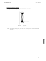
Layout of the connectors on the board
The figure below shows the physical layout of the connectors on the board.
B13 A13
B12 A12
Polarity indication
B2 A2
B1 A1
Board end
Note
[Top View]
When actually arranging the pins, design them according to the connector dimensional
information.
9
KIT-VR5400-TP
User’ s Manual
6. PRECAUTIONS
This chapter provides precautionary information on the use of KIT-VR5400-TP.
Precautions related to operation
1) Do not turn on the power to the user system while the power to KIT-VR5400-TP is off. Doing so can
cause a malfunction.
2) KIT-VR5400-TP externally controls the debugging control circuit built into the CPU. Consequently,
KIT-VR5400-TP does not operate correctly unless the following conditions are satisfied:
* KIT-VR5400-TP is properly connected to the user system using the N-Wire cable.
* The power to the user system is on so that the CPU can run correctly.
Precautions related to functions
1) The disassembly and display of real-time trace data is performed by reading the contents of memory
at the point the trace display command is issued, according to the branching information received
from the CPU. Consequently, the disassembly and display of the program located in RAM of the
user system is not correct if changes (including erroneous writing due to a CPU hang up) are made
after program execution. Note that the following functional contraints must be observed.
a. Analysis and display cannot be made correctly if the branch information contains an error.
10