1
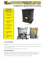
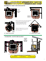
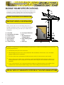
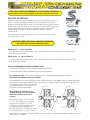
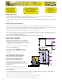
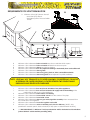
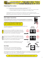
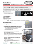
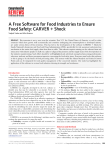
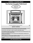
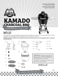
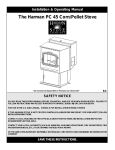
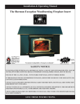
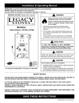
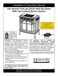
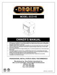
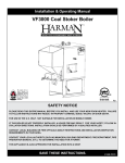
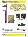
CORN STOVE
OPERATIONS &
INSTALLATION
GUIDE
CORN BURNING
SHOP & GARAGE
HEATERS
Manufactured by
Marketed by
For the following models: CC2, CC3, CCGB2, CCGB3
Installations shall conform to:
CAN/CSA B365 Installation Code For Solid-Fuel-Burning Appliances and Equipment in Canada and
NFPA 211 Chimney, Fireplaces, Vents and Solid Fuel Burning Appliances in the USA
READ THIS ENTIRE MANUAL BEFORE INSTALLING YOUR CORN STOVE/HEATER/INSERT. FAILURE TO
FOLLOW INSTRUCTIONS MAY RESULT IN PROPERTY DAMAGE, BODILY INJURY OR EVEN DEATH
FOREWORD TO
NEW OWNERS
Dear Corn Stove Owner,
Congratulations on the purchase of your corn burning stove. You
have selected the finest in corn heating technology.
This guide will walk you through the proper operation & installation of
your corn burning stove, heater or insert. This guide will provide you
with valuable information regarding placement of the appliance,
different installation options, and exhaust considerations.
Please note the following points regarding stove installation and
corn heating in general:
- Whether you install your stove yourself or hire a professional
installer, a quality installation is a must for the safety of your family
as well as efficient, satisfactory operation.
- Initial setup of the stove is the most important step to ensure
consistent, comfortable operation.
- Know the quality and characteristics of the corn you burn. Corn
can vary greatly from company to company, from load to load
and even from bag to bag.
- BE DILIGENT IN YOUR CLEANING PROGRAM.
- Remember that most operational dilemmas with corn stoves arise
from improper installation, poor quality corn, lack of timely
cleaning or incorrect air flow adjustment.
With a minimum amount of consistent care, your corn burning stove
will provide years of clean, efficient, comfortable and environmentally
sound heating.
UPDATES
Updated manuals, product registration and warranty information can be found on our website:
www.dansons.com/support
Thank you for selecting our corn burning stoves!
Sincerely,
Dansons Group Inc. and Canadian Comfort Industries
We do NOT recommend corn stoves as your only source of heat.
Do NOT install in a sleeping room.
Use of outside air is highly recommended with our corn stoves & heaters.
Do not operate with the front door or hopper lid open.
Keep children, furniture, fixtures and all combustibles away from any heating appliance.
Installation and use of a carbon monoxide detector is highly recommended.
2
INSTALLATION &
PLANNING CHECKLIST
Unless you are knowledgeable and experienced in stove installation, we recommend your stove receive
a pre-delivery check and be installed by your local specialty retailer or certified HVAC service depot.
COMPLETE THIS CHECKLIST PRIOR TO INSTALLING YOUR CORN STOVE:
Carefully read this INSTALLATION GUIDE. SAVE THIS GUIDE FOR FUTURE USE!
Have your local Dealer demonstrate all operational, cleaning & maintenance steps necessary for
your stove.
Select an install location. The design of your home and placement of the stove will determine its
value as a source of heat. A corn stove depends primarily on air circulation to disperse its heat.
There are other practical considerations to be considered before final placement is decided:
eg. existing chimneys, corn fuel storage, aesthetic considerations, roof design (rafter location &
roof pitch), room traffic, clearances to combustibles, existing wiring, heat loss
NOTE: Placing a unit in an uninsulated area greatly reduces heat capability (ie. cement basement,
uninsulated steel building, etc.
Installation of this appliance must conform to local codes and applicable state/provincial/federal
requirements. Becoming familiar with these requirements before installation is essential.
Register your purchase online at www.dansons.com/support.
COMPLETE THIS CHECKLIST WHILE INSTALLING YOUR CORN STOVE:
Determine the location and measurement needed for your chosen location.
Be sure to pre-fit all items before you fasten or install the stove or venting permanently.
IMPORTANT: Use ONLY type L or PL corn venting for your venting installation.
Do NOT use plastic piping!
Ensure ALL joints of L vent, PL vent are tightly connected, sealed with RTV silicone (including exhaust
connector) and is correctly installed.
Follow the vent manufacturer’s instructions.
Verify that the stove is plugged into a 3 pronged grounded outlet, NON GFI (ground fault interruptor)
NOTE: We STRONGLY recommend the use of a surge protector to protect the circuitry in your
control board.
For outside air, use metal pipe ONLY, either solid or flexible. PVC or any other non-metallic
material MUST NOT BE USED.
For more information regarding corn stove operations or other specifications, please read the
OPERATIONS GUIDE section of this manual. Updated guides are available online at
www.dansons.com/support.
3
HOME/SHOP HEATER
CONFIGURATIONS
HOME/SHOP HEATER SPECIFICATIONS
MINIMUM
CLEARANCES TO
COMBUSTIBLES
1” from BACK of stove
to combustibles
10” from SIDE of stove to
combustibles
1” from BACK CORNER
of stove to
combustibles
16” from TOP of stove
to combustibles
120 CORN HEATER
26”
24”
3” from PL VENT to
combustibles
6” non-combustible
surface in FRONT
of stove
31 1/2”
36” to drapes, doors,
anything that can
swing
8 1/4”
Exhaust
+
+
8 3/4”
3 3/4”
Air Inlet
14 1/4”
STOVE PLACEMENT
The stove must be placed so that no combustibles are within, or can swing within (ie. drapes, doors) 36” of the
stove itself.
If the stove is placed in a location where the ceiling height is less than 7’, it must follow the requirements in the
ALCOVE INSTALLATION section.
The stove & floor protection must be installed on a level, secure floor.
FLOOR PROTECTION
The stove must be installed on a non-combustible floor protector (ie. sheet steel with cement, tile, slate)
extending the full width and depth of the stove and extending 6” in front of the stove. The floor protector
needs to be a minimum 24.5” deep x 30.5” wide and must be a minimum 0.018” thick (26 gauge).
Floor protection must extend under and 2” to each side of a chimney tee (if used).
4
HOME/SHOP HEATER
CONFIGURATIONS
CLEARANCES: ‘DIRECT VENT INSTALLATION’
18”
3”
1”
1”
10”
10”
DIRECT
THROUGH
WALL
10”
INTERIOR
VERTICAL
6”
6”
6”
NOTE: If interior vent is used, the clearance
to the back wall is determined by the
upward-turned elbow or TEE. It
will vary in depth de;ending
on the brand of PL vent used.
18”
1”
1”
3”
10”
6”
Before placing the stove, connect
the elbow or TEE and measure off
the 3” clearance.
10”
6”
o
o
45 CORNER INTERIOR CORNER
45 CORNER THROUGH WALL
CLEARANCES: ‘ALCOVE INSTALLATION’
ALCOVE
DIRECT
THROUGH
THE WALL
18”
1”
1”
16”
10”
10”
10”
6”
6”
Due to radiant heat from the side panels, home/shop heaters require more space for placement.
Minimum clearances to combustibles:
1” from the back
16” from the top
10” from the sides
5
MOBILE HOME
CONFIGURATIONS
MOBILE HOME SPECIFICATIONS
Your corn stove has been tested and listed for mobile home
installation. Please carefully follow the directions below and
note all pertinent specifications for your own installation.
L
K
CAUTION: DO NOT INSTALL IN ANY SLEEPING ROOM!
THE STRUCTURAL INTEGRITY OF THE MANUFACTURED
HOME FLOOR & CEILING/ROOF MUST BE MAINTAINED!
J
NOTE: Check with your local building inspector or
qualified installation person to verify that all installation
specifications are being met with your mobile home
installation.
A - Floor Pad
B - Combustion Air Intake
C - Fresh Air Duct
D - Fresh Air Hood
E - Stove Exhaust
F - Pipe Adapter
G - Clean-Out Tee
H - Tee Support Bracket
I - Pipe
J - Fire Stop Spacer/
Ceiling Support
K - Roof Flashing/Storm
Collar
L - Rain Cap
I
H
G
A
B
C D
In addition to all previously detailed installation requirements, mobile home installations must meet the
following requirements:
. Permanently bolt your stove to the floor
. Electrically ground your stove or the pedestal to the steel frame of the home. Use a number 8
gauge copper wire or equivalent
. The stove must have a permanent outside air source with a 1/4 inch screen over the inlet
. When moving your mobile home, all exterior venting MUST BE REMOVED while the mobile home
is being relocated. Upon completion of relocation, all venting must be reinstalled and securely
fastened.
. PL or L vent must be 3” or 4” and must extend a minimum of 36 inches above the roofline of the
mobile home and must be installed using a UL/ULC listed ceiling fire stop and rain cap
INSTALL VENT AT CLEARANCES SPECIFIED BY THE VENT MANUFACTURER.
6
OUTSIDE AIR
CONSIDERATIONS
A fresh air kit is HIGHLY RECOMMENDED for all corn appliance installations.
If an outside air source is not supplied, a negative air situation may occur.
NEGATIVE AIR PRESSURE
Negative indoor air pressure results when more air is leaving your home
than is coming in, creating a partial vacuum. In winter, the heated
indoor air rises up through the home and escapes from upper level leaks.
At the same time, we force air out of the house with kitchen & bath fans,
clothes dryers, furnaces, fireplaces and water heaters, all of which
contribute to the negative pressure problem, which is a lack of
“make-up air”.
FRESH AIR KIT 3’
This can lead to annoying situations such as a stove that won’t draw
or possibly leaks smoke.
WITHOUT PLANNED VENTILATION, NEGATIVE AIR PRESSURE
WILL DRAW AIR IN AT UNCONTROLLED POINTS.
FRESH AIR KIT 10’
FRESH AIR KIT, 3’: Part # ACFAKT03
1 x 2” galvanized hood with screen, 1 x 2” aluminum flex duct (compressed 15”, extends to 36”),
2 x 2” worm gear clamps
FRESH AIR KIT, 10’: Part # ACFAKT10
1 x 2” galvanized hood with screen, 1 x 2” aluminum flex duct (compressed 48”, extends to 120”),
2 x 2” worm gear clamps
FRESH AIR REQUIREMENTS AND RECOMMENDATIONS
Outside air is REQUIRED ON ALL MOBILE HOME INSTALLATIONS
Outside air is HIGHLY RECOMMENDED for all other installations
Use metal pipe ONLY, either solid or flexible, for your outside air installation (see A below).
NON-METALLIC MATERIAL MUST NOT BE USED!
A wind shield (B) over the termination of the outside air pipe or a 90 degree elbow or bend directed
away from the prevailing winds MUST be used when an outside air pipe is installed through the side
of a building. Keep the outside air pipe
termination at least 1 foot away from
C
C
the exhaust system termination
When outside air is taken from an
existing chimney, the exhaust system
MUST NOT terminate in the same
chimney
The outside air pipe on your stove is
2” O.D. The outside air connecting
pipe must be at least 2” I.D. The
outside air connecting pipe must be
as short and as free of elbows as
possible, and MUST FIT OVER, not inside,
the outside air pipe on your stove (C)
A
A
B
B
NOTE: When extending the fresh air intake more than 10 feet, it is recommended to increase the vent
diameter to 3” or larger.
7
EXHAUST
SYSTEMS
DO NOT CONNECT THE
CORN VENT TO A VENT
SERVING ANY OTHER
APPLIANCE OR STOVE
CORN VENT MUST MAINTAIN A
MINIMUM 3” CLEARANCE TO ANY
COMBUSTIBLE (INSTALL VENT AT
CLEARANCES SPECIFIED BY THE
VENT MANUFACTURER)
DO NOT INSTALL A
FLUE DAMPER IN THE
EXHAUST VENTING SYSTEM
OF THIS UNIT
CORN VENT TYPE
Corn venting must be approved 3” or 4” diameter type PL or L. You must vent your stove directly to the
outside in one of the configurations shown in the diagram below.
Use 4” diameter venting if vent or vent liner height is over 15 feet or if the installation is over 4000 feet above
sea level.
CORN VENT INSTALLATION
Termination must exhaust above the air inlet elevation and parallel or above the exhaust output of the
pellet appliance. It is recommended that at least 3 feet of vertical pipe be installed to create natural draft.
This is to help prevent the possibility of smoke or odor during appliance shut down.
Horizontal sections must have a 1/4” rise every 12” of travel after 3 feet.
Corn vent connections must be sealed with high temperature RTV silicone and/or screwed together with a
least 3 x 3/8” long stainless steel screws.
Seal each vent section by injecting a liberal amount of this silicone into the gap.
CORN VENT DISTANCE
33’
Maximum venting height is 33 feet. Maximum
o
horizontal offset is 5 feet. Use no more than 180
o
o
of elbows (eg. 2 x 90 elbows, or 2 x 45 elbows &
o
1 x 90 elbow, etc) plus termination.
30’
25’
Vent must have a support bracket every 5 feet
when on the exterior wall.
Use 4” Diameter “PL” Vent
If venting outside of
shaded area.
20’
Vent height and run MUST NOT exceed the
distance shown in the unshaded region of
the chart.
Use 3” or 4” Diameter
“PL” Vent, if venting in
shaded area.
15’
To achieve optimum performance,
KEEP VENT RUNS AS SHORT AS POSSIBLE,
especially on horizontal installations.
10’
CORN VENT TERMINATION
5’
Termination must be a minimum of 6” above
the chimney (NOTE: Chimney must meet
local codes for height above the roof or other
obstructions)
0’
(diagram not to scale)
There must be an approved cap to prevent
o
water from entering the pipe shaft, or a 45
elbow downturn
0’
5’
If the termination is located on a windy side of the house, an approved house shield is recommended to
prevent soot from accumulating on the side of the house
Termination must NOT be located where snow or other materials will plug it
There must be a metal seal plate or a wall thimble at the wall juncture
8
EXHAUST
SYSTEMS
REQUIREMENTS FOR VENT TERMINATION
A
Minimum 3 feet (36”) above the roof
and 2 feet (24”) above
the highest point of the roof within
10 feet
A
3’
2’
10’
M
Q
F
E
N
K
H
B
B
D
C
L
P
J
F
B
C
D
E
F
G
H
G
I
O
Minimum 4 foot clearance below or beside any door or window which opens
Minimum 1 foot clearance below or beside window that does not open
Minimum 1 foot clearance above any door or window
Minimum 3 foot clearance from any adjacent building or horizontally from combustible wall
Minimum 1 foot clearance above grade
Minimum 2 foot clearance above any grass, plants or other combustible materials
Minimum 7 foot clearance above any grade when adjacent to public walkways
NOTE: VENT MAY NOT TERMINATE IN COVERED WALKWAY OR BREEZEWAY OR ABOVE
A SIDEWALK OR PAVED DRIVEWAY LOCATED BETWEEN TWO SINGLE FAMILY
DWELLINGS AND SERVES BOTH DWELLINGS
I
J
K
L
M
N
O
P
Q
Minimum 3 foot clearance from any forced air intake of any other appliance
Minimum 4 foot clearance from a non-mechanical air supply inlet to the building or the
combustion air inlet to any other appliance
Minimum 2 foot clearance below eaves or overhang
Minimum 1 foot clearance to an outside corner from the center of the pipe
Minimum 1 foot clearance to an inside corner
Minimum 3 foot clearance above a gas meter/regulator assembly when measured from
the center line of the regulator
Minimum 6 foot clearance to service regulator vent outlet
Minimum 3 foot clearance under a veranda, porch, deck or balcony (NOTE: Only
permitted if veranda, porch, deck or balcony is fully open on sides beneath the floor)
*** VERY IMPORTANT ***: Minimum 1 foot beyond exterior wall for horizontal vent terminations
(extend further if outside wall has prevailing wind)
9
OPERATING YOUR
CORN BURNING STOVE
GENERAL OPERATIONS
NOTE: When burning corn it is CRITICAL that you use
only clean dry corn (14% moisture content or below).
The drier & cleaner the fuel, the better. Have your
fuel at room temp. before filling hopper.
CRITICAL: Residue such as fines (dust), husks, cobs or
stalk fragments will very likely cause uneven feed and
or cause auger jams.
To avoid problems, we strongly recommend screening
your corn.
Before proceeding, ensure that your air damper rod is
open between 3/16” & 1/2”, depending on moisture
content of corn and vent run.
Start your stove with the Agritron Grate as follows:
1. Firmly press the START button, then OFF
2. Place 2 handfuls of wood pellets in the bottom of the grate. Proprietary starters or rolled up newspaper
may be used in the place of wood pellets, though they may not work as well.
3. Light the pellets and close the door part way until the pellets are burning briskly (7 to 9 minutes).
4. Close and latch the door securely and restart the system to feed fuel (turn the auger switch on if
applicable).
5. Turn the fuel feed to #3 setting for at least 30 minutes*. This is necessary to build up an adequate bed
of coals to maintain combustion at lower feed settings.
* NOTE: You may need to experiment with the length of time at #3 setting as different hybrids of
corn and moisture levels present different burn characteristics.
The pellets at startup must be burning very hot in order for the corn to ignite.
NOTE: To prevent grate overloading, you may not be able to operate the stove above fuel setting #3..
6. If necessary, adjust the air damper (air intake) so that you have a brisk flame. See your owners manual
for additional information on this adjustment as it is critical that you have the proper air adjustment for
satisfactory burning
10
OPERATING YOUR
CORN BURNING STOVE
Cleaning Procedure:
When the grate starts to fill up you will need to complete the following:
a. Shut the stove off and remove pellet chute guard
b. Remove the grate and dump ash & clinker out of the grate into a metal container
c. If residue adheres to the grate, use an edged tool to scrape it away
Cleaning intervals will vary in time from a low of 8 hours to as much as 30 hours or more
depending on such factors as fuel feed rate, hybrid being used, cleanliness and dryness of fuel.
Reinsert your grate and restart as per items 1-5 on the previous page.
FINE TUNING YOUR STOVE
Once the damper rod is set and your corn is burning steadily (ie. no popcorning),
you are ready to fine tune your stove. Fine tuning is required due to the differences
in installation configuration, geography, insulation of the home, and quality of corn.
Do NOT use a metal object to adjust your trim
pots. Try using a plastic non-metallc object
(eg. insulated shaft screwdriver, pen cap, etc.)
PELLET
CORN
First, switch to feed rate #1 by pressing the START / FEED RATE button
until the #1 LED lights up.
Turn the #1 trim pot COUNTER CLOCKWISE until the dial
stops, then turn back to 8-2 o’clock position as illustrated.
Turn the #4 trim pot CLOCKWISE until the dial stops, then
turn back to 10-4 o’clock position as illustrated.
Turn the #1 trim pot COUNTER CLOCKWISE until the dial
stops, then turn back to 9-3 o’clock position as illustrated.
Turn the #4 trim pot CLOCKWISE until the dial stops, then
turn back to 9-3 o’clock position as illustrated.
By adjusting the trim pots as described above, you are
ensuring that your stove is now at its optimal settings.
Fuel Rates
At this point, your stove should still be running on
the #1 setting (low). Let this burn for approximately
10 minutes before making any further adjustments.
TRIM POTS
WITH FACTORY
DEFAULT SETTINGS
FUEL
FEED RATE
SETTING #1
(LOW)
FUEL
FEED RATE
SETTING #4
(HIGH)
FUEL
FEED RATE
SETTING #1
(LOW)
FUEL
FEED RATE
SETTING #4
(HIGH)
CLOCKWISE
DECREASES
feed rate
COUNTERCLOCKWISE
INCREASES
feed rate
Fuel feed rate at the lowest (#1) and highest (#4) settings can be changed by adjusting the #1 or #4 trim
pots located on the control panel. To INCREASE fuel feed rate, turn the trimmer COUNTER CLOCKWISE.
To DECREASE fuel feed rate, turn the trimmer CLOCKWISE.
ALSO: The #1 and #4 trim pot dials ONLY adjust fuel feed rates 1 and 4.
11
SAFETY
PRECAUTIONS
Do NOT operate if you smell smoke coming from your corn appliance. Push OFF on the control
board, monitor your stove and call your dealer.
NEVER USE GASOLINE, GASOLINE-TYPE LANTERN FUEL, KEROSENE, CHARCOAL LIGHTER FLUID or
similar liquids to start or ‘freshen up’ a fire in this appliance. Keep all such liquids well away from
the stove while it is in use.
Do NOT unplug the heater if you suspect a malfunction. Push OFF on the control board and
inspect the heater.
Do NOT operate the stove if the flame become dark & sooty or if the burn pot overfills with corn.
Push OFF on the control board and periodically inspect the stove.
NEVER try to repair or replace any part of the stove unless instructions for the consumer are
given in this guide. All other work should be done by a trained technician.
The viewing door and ash bin must be closed and latched during operation.
NEVER block free airflow through the open vents of the unit.
Contact your local building officials to obtain a permit and information on any installation
restrictions or inspection requirements in your area. Notify your insurance company of this stove.
The corn appliance exhaust system works with negative combustion chamber pressure and a
slightly positive chimney pressure. Therefore the exhaust system MUST BE COMPLETELY AIR TIGHT
and properly installed. All pellet joints must be sealed with HI-TEMP RTV SILICONE SEALANT and
at least 3 sheet metal screws to each other as well as to the stove.
This unit must be properly installed to prevent the possibility of a house fire. The instructions must
be strictly adhered to. Do NOT use makeshift methods which may compromise the installation.
Your stove requires periodic maintenance and cleaning. Failure to maintain your stove may
lead to smoke spillage in your home.
Allow the appliance to cool before carrying out any maintenance or cleaning. Ashes must be
disposed of in a metal container with a tight fitting lid. The closed container of ashes should be
placed on a non-combustible surface or on the ground well away from all combustible materials
pending final disposal.
This stove is designed and approved for shelled corn fuel and wood pellets. Any other type of
fuel burned in this stove may void the warranty and safety listing.
This appliance will not operate during a power outage. If a power outage does occur, check the
stove for smoke spillage and open a window if any smoke spills into the room.
Keep foreign objects out of the hopper.
12
SAFETY
PRECAUTIONS
Disconnect the power cord before performing any maintenance. IMPORTANT: Touching the OFF
button on the control board does NOT disconnect power to the stove.
DO NOT THROW YOUR INSTRUCTIONAL GUIDE AWAY. This guide have important operating &
maintenance information that you will need at a later time.
Do not place clothing or other flammable items on or near the stove. Because this stove can be
controlled by a thermostat, there is a possibility of it starting and igniting any items placed on or
near it.
This appliance must be connected to a standard 110 - 120V, 60 Hz grounded electrical outlet. Do
NOT use an adapter plug or sever the ground plug. Do NOT route the electrical cord underneath,
in front of or over the appliance.
It is highly recommended to connect the stove to a standard 110 120V ground surge protected
unit or surge protected outlet.
When installed in a mobile home, the heater must be bolted to the floor, have outside air, and
MUST NOT BE INSTALLED IN THE BEDROOM (per H.U.D. requirements). Check with local building
officials.
Educate all children on the dangers of a high temperature stove.
Young children should be supervised when they are in the same room as the stove.
NEVER PUT YOUR FINGERS NEAR THE AUGER. Pellet fuel is fed to the burn grate by a screw auger
that is driven by a high torque motor. The auger can start and stop automatically anytime while
the stove is operating.
Do NOT connect this appliance directly to air ducts or any air distribution system. This will void any
warranty.
Do NOT burn with insufficient combustion air. A periodic check is recommended to ensure proper
combustion air is admitted to the combustion chamber. Setting the proper combustion air is
achieved by adjusting the slide damper rod located on the side of the appliance.
It is advisable to clean the exhaust vent bi-annually or every two tons of corn burned.
Soot or creasote may accumulate when the stove is operated under incorrect conditions such as
an extremely rich burn (black tipped, lazy orange flames).
Do NOT use insulated or plastic pipes when installing your venting. Make sure to allow at least 24
hours for all joints to seal properly or the seal will expand and allow smoke to vent into the room.
PLEASE NOTE: Dansons Group Inc. and Canadian Comfort Industries grant no warranty, implied or
stated, for the installation or maintenance of your stove and assume no responsibility for any
consequential damage(s).
13
LIMITED
WARRANTY
CANADIAN COMFORT INDUSTRIES (CCI) LIMITED WARRANTY
CCI wood pellet and corn appliances carry a one (1) year -parts only- on electrical components
and a five (5) year limited warranty from the date of sale to the original owner against defects
and workmanship on all steel parts (excluding the burn grate and the heat tube scraper / rod).
If defective in material or workmanship, during the warranty period, CCI will, at its option, repair
or replace the product as described below.
There specifically is NO warranty on paint or plated surfaces, glass, burn grate, fire brick and all
gaskets or against damage caused by corrosion. There is no warranty coverage for variances in
fuel feed rates. BTU heat rating will vary with different fuel conditions and is not considered a
defect if the unit does not feed a constant amount of fuel.
The warranty above constitutes the entire warranty with respect to Canadian Comfort Industries.
CCI MAKES NO OTHER WARRANTY, EXPRESSED OR IMPLIED, INCLUDING “ANY” WARRANTY OF
MERCHANTABILITY, OR WARRANTY OF FITNESS FOR A PARTICULAR PURPOSE. No employee, agent,
dealer, or other person is authorized to give any warranty on behalf of CCI. This warranty does not
apply if the product has been altered in any way after leaving the factory. CCI and its agents
assume no liability for “resultant damages of any kind” arising from the use of its products. In
addition, the manufacturer and its warranty administrator shall be held free and harmless from
liability from damage to property related to the operation, proper or improper, of the equipment.
THERE ARE NO WARRANTIES WHICH EXTEND BEYOND THE DESCRIPTION ON THE FACE HEREOF.
THESE WARRANTIES APPLY only if the device is installed and operated as recommended in the
user’s manual.
THESE WARRANTIES WILL NOT APPLY if abuse, accident, improper installation, negligence, or use
beyond rated capacity causes damage.
HOW TO MAKE A CLAIM – Any claim under this warranty should be made to the dealer from whom
this appliance was purchased. Then contact is made with the manufacturer, giving the model
and serial numbers, the date of purchase, your dealer’s name and address, plus a simple
explanation of the nature of the defect.
THIS WARRANTY IS LIMITED TO DEFECTIVE PARTS – REPAIR AND/OR REPLACEMENT AT CCI’s OPTION
AND EXCLUDES ANY INCIDENTAL AND CONSEQUENTIAL DAMAGES CONNECTED THEREWITH. A
DEFECTIVE PART DOES NOT WARRANT THE REPLACEMENT OF THE ENTIRE UNIT.
WARRANTY EXCLUSIONS: Failure due, but not limited to, fire, lightning, acts of God, power failures
and/or surges, rust, corrosion and venting problems are not covered.
AUGER JAMS ARE NOT COVERED UNDER WARRANTY.
Damage and/or repairs including but not limited to; knobs, handles, door gaskets, log sets, paint
and plated surfaces – trim, baffles, louvers or handles. Additional exclusions for corn stoves are
burnpot housing weldment and burnpot warpage (corn or pellet). Additional or unusual utility
bills incurred due to any malfunction or defect in equipment are not covered.
REMOVAL OR REINSTALLATION COSTS ARE NOT COVERED BY THIS WARRANTY.
CCI LIABILITY IS LIMITED TO THE WHOLESALE COST OF THE STOVE.
Some states do not allow the exclusion or limitation of incidental or consequential damages, or
limitations of implied warranties; therefore the limitations of exclusions set forth in this warranty may
not apply to you. This warranty gives you specific legal rights, and you may have other rights,
which vary from state to state. All disputes relating to this warranty shall be tried before the courts
of Alberta, Canada.
Your purchase must be registered with Canadian Comfort Industries. This can be done at:
www.dansons.com/support or by faxing your proof of purchase to us at: 1-877-303-3135.
14
LIMITED
WARRANTY
WARRANTY REGISTRATION
THIS REGISTRATION INFORMATION MUST BE ON FILE FOR THIS WARRANTY TO BE
VALID. PLEASE MAIL/FAX THIS INFORMATION WITHIN THIRTY (30) DAYS FROM
THE DATE OF PURCHASE.
Name of Purchaser: ____________________________________________________________________________________
Address: _______________________________________________________________________________________________
City: _______________________________________________ State / Province: __________________________________
Zip: ________________________________ Telephone: _______________________________________________________
Email Address: _________________________________________________________________________________________
DEALER INFORMATION
Purchased From (Dealer): _______________________________________________________________________________
Address: _______________________________________________________________________________________________
City: _______________________________________________ State / Province: __________________________________
Zip: ________________________________ Telephone: _______________________________________________________
UNIT INFORMATION
(Please refer to rating plate on back of stove or under hopper lid to complete this section)
Model Number: ___________________________________ Purchase Date: _____________________________________
Serial Number: ____________________________________ Purchase Price: _____________________________________
How did you first hear about our product? (please check one)
Word of Mouth
Trade Show
Internet
Other: __________________________________________________________
Where did you receive information about our product? (please check one)
Telephone
Internet:
Dealer
Name of Dealer: __________________________________________
Other: __________________________________________________________
Check here if you would like more information sent to you about our other products
Canadian Comfort Industries
Mail to:
26319 Township Road 531
Acheson, Alberta Canada
Fax to:
Toll Free: 1-877-303-3135 24 hours a day
Online:
Visit www.dansons.com/support
T7X 5A3
My local Dansons dealer is:
To register your purchase, visit www.dansons.com/support
Technical Support
Monday to Friday, 9 am to 8 pm EST
Saturday, 11 am to 7 pm EST
1-866-456-9269
COPYRIGHT
Copyright 2006, Canadian Comfort Industries. All rights reserved.
No part of this manual may be copied, transmitted, transcribed, stored in a retrieval system in any
form or by any means without the expressed written permission of:
Canadian Comfort Industries 26319 Twp Rd 531 Acheson, AB Canada T7X 5A3 1-877-303-3134